Week 3 - External flow simulation over an Ahmed body.
External flow simulation over an Ahmed body
Obejective :
Describe Ahmed's body and its importance.
Explain the reason for the negative pressure in the wake region.
Explain the significance of the point of separation.
Expected Results:
Velocity and pressure contours.
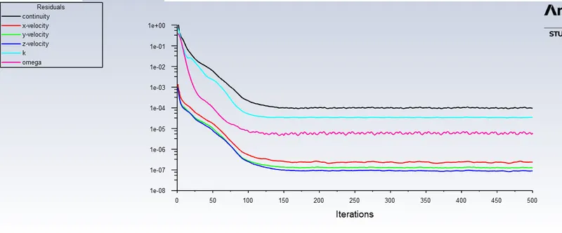
The drag coefficient plot for a refined case. ( For velocity of 25m/sec, the drag coefficient should be around 0.33).
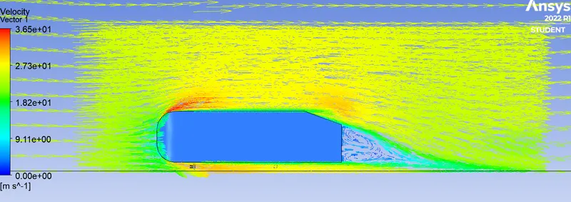
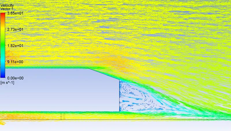
The vector plot clearly showing the wake region.
Perform the grid independency test and provide the values of drag and lift with each case.
INTRODUCTION
The Ahmed body is simplified car body used in automotive field to study the impact of the flow pattern on the drag. The external aerodynamics of the car defines many major traits of an automobile like stability, comfort and fuel consumption at high speeds. The flow around the vehicle is characterized by high turbulent and three dimensional flow separations as well as there is a growing need for more insight into the physical features of these dynamical flows. The Ahmed Body is a simplified car, used in automotive field to investigate the flow analysis and find the wake flow around the body. Ahmed body is made up of round front part, a moveable z slant plane in the rear of the body to study the detachment phenomena at different angles, and a rectangular box which link the front part and the rear slant plane. The principal objective to study such a simplified car body is to tackle the flow processes involved in drag production. Through perceiving the mechanisms involved in creating drag one can be able to design a car to minimize drag and therefore reducing fuel consumption and maximize vehicle performance
The "Ahmed" body, has the form of a highly simplified car, consisting of a blunt nose with rounded edges fixed onto a box-like middle section and a rear end that has an upper slanted surface (like a "hatch-back" car), the angle of which can be varied. The model is supported on circular-sectioned legs or stilts, rather than wheels. Despite neglecting a number of features of a real car (rotating wheels, rough underside, surface projections, etc.) the Ahmed Body generates the essential features of flow around a car, namely: flow impingement and displacement around the nose, relatively uniform flow around the middle and flow separation and wake generation at the rear.
Besides the analyses of the velocity field, the Ahmed Body is also used for drag force and lift force analyses and rolling, pitching and yawing moments. The slant angle on the back allows studying the separation region and its influence on the velocity profile and forces.
The geometry of the Ahmed body is shown in the figure below. The slant angle is adjustable and is the main variable model parameters in the experimental investigations. The Ahmed body, of length (L) 1044 mm, height (H) 288 mm, and width (W) 389 mm, was placed at 50 mm from the ground.
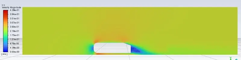
Now we are going to see the results of Velocity and pressure contours from the base mesh (0.2m)
step 1 : Geometry setup
default i will be in (mm) convert into (m)
drag the Ahmad body STEP file
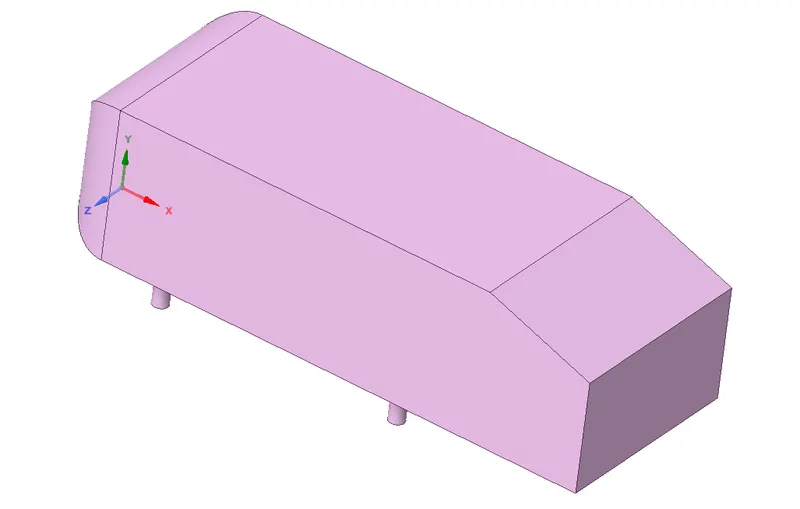
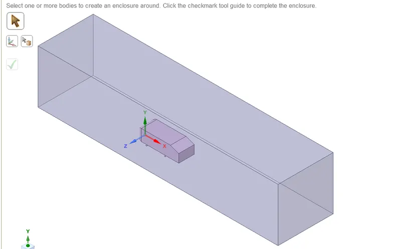
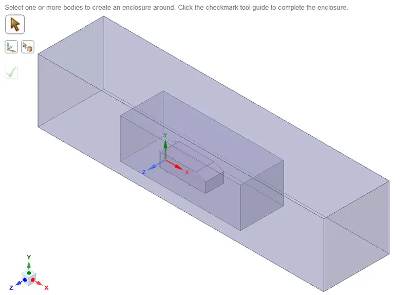
we need to use the 'split body' command in SpaceClaim to perform the operation and then you can use the symmetry boundary condition in fluent to perform the simulation.
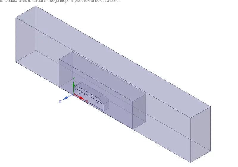
Step 2 : Meshing
Define the boundrys inlet,outlet, symmetrys, car-wall
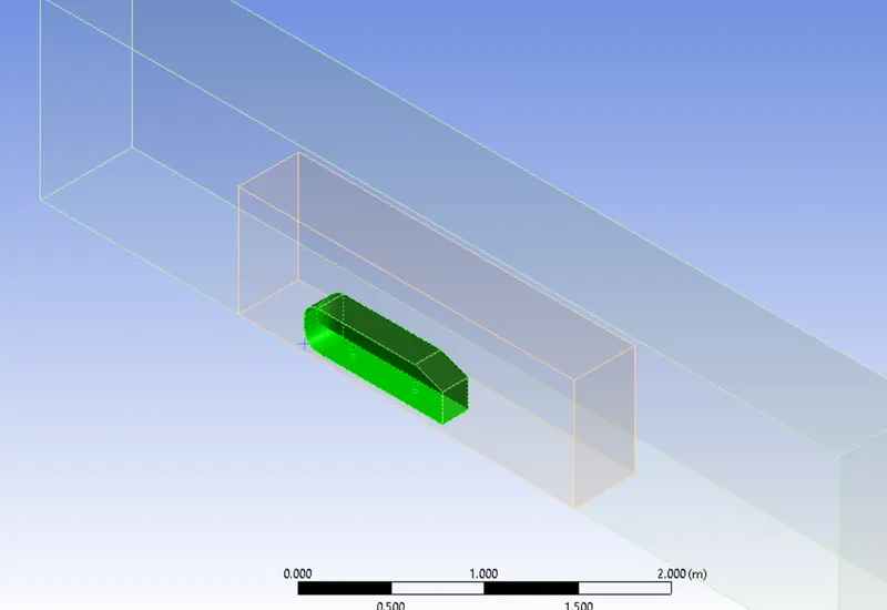
we are simulating results for a base mesh so 0.2m is the mesh size
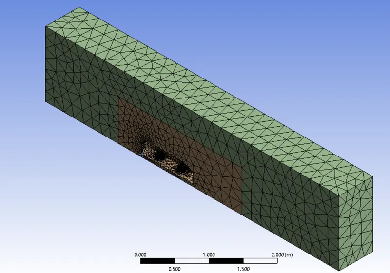
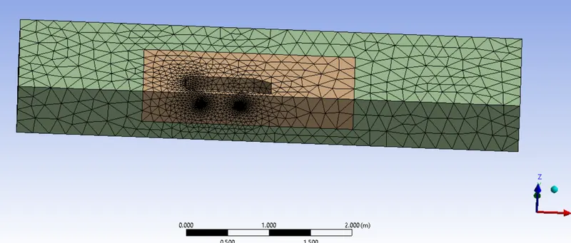
Meshing is done
Step 3 :
case setup
Solver type: Pressure based
Check the Energy equation Turblent Model: K-Omega SST model
Fluid Material: Air
Boundary conditions
Inlet velocity: 25 m/s
Outlet pressure: 0 pa
Symmetry: For side walls
Wall : Bottom,
Reference value
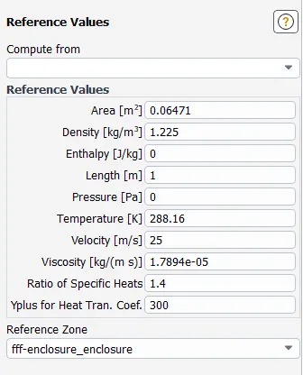
Get Initalize
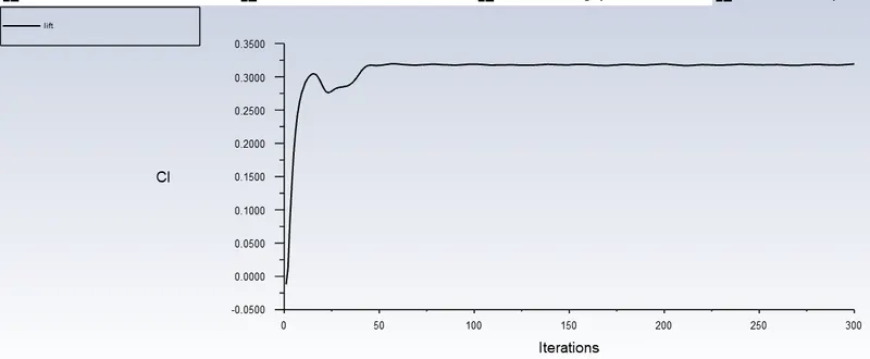
creat Cd, Cl, plots
creat a plane towards z direction to get a velocity pressure counters
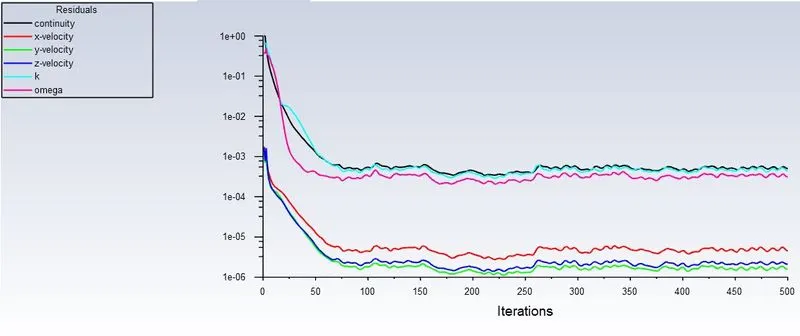
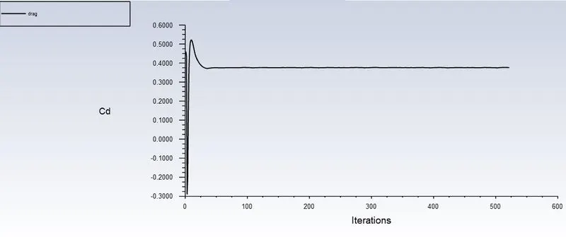
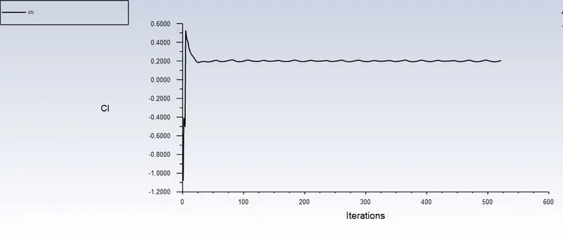
We got Cd 0.4 in the challange they asked 0.33 so we refined the mesh and get the correct value
Velocity Counture
Pressure Counture
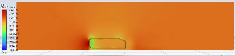
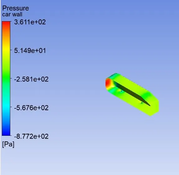
The drag coefficient plot for a refined case. ( For velocity of 25m/sec, the drag coefficient should be around 0.33).
For getting the Cd value of 0.33 we manulaptuted the value of thinkness of a car wall by inflaction metod
giving 0.6 max size , layer of 5, and groth rate of 1.2
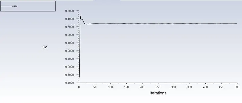
Cd of 0.33 requried result
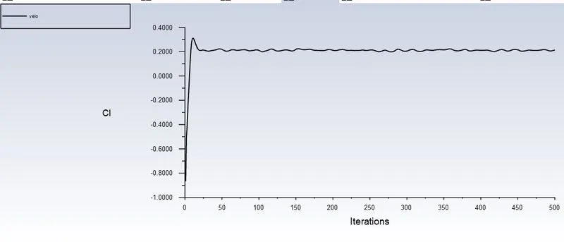
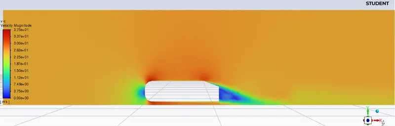
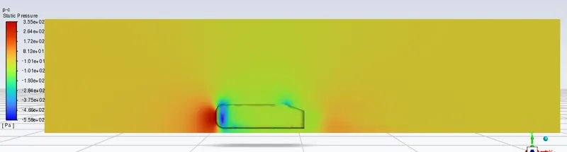
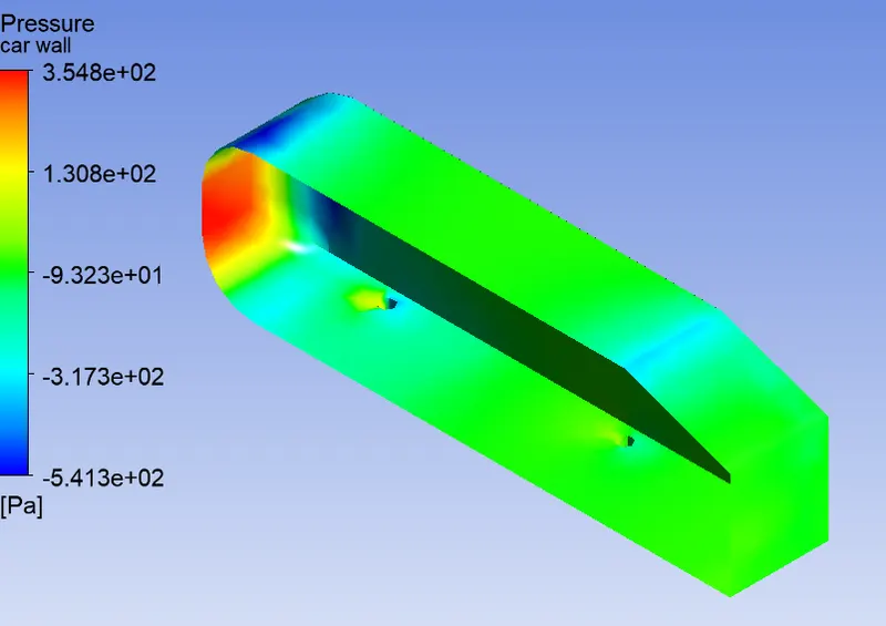
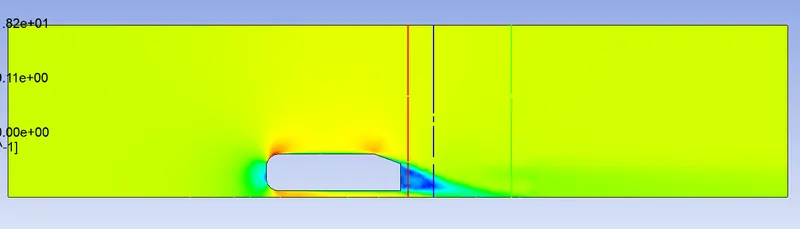
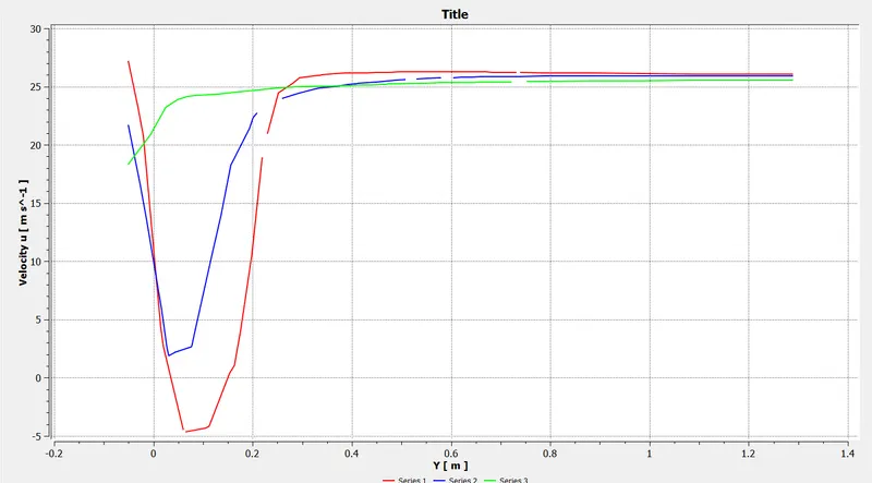
where red=1.1m , blue=1.3m, green=1.9m from the Ahmed body.
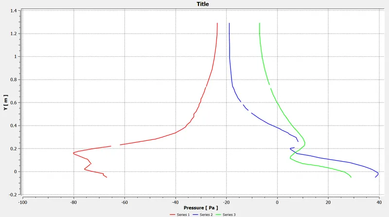
Negative pressure gradient in wake region.
The vector plot clearly showing the wake region.
Perform the grid independency test and provide the values of drag and lift with each case.
Case1 : 0.3 m Grid
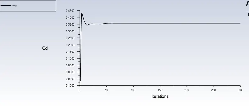
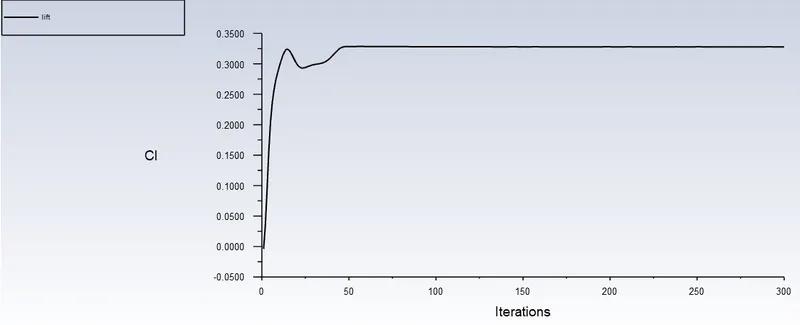
Case 2 : 0.05
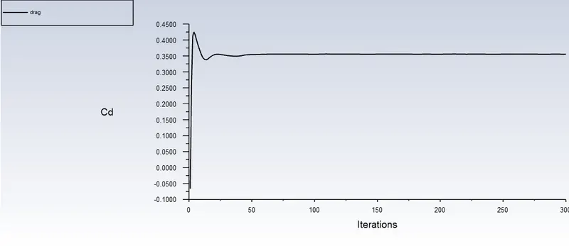
Negative pressure gradient
When fluid velocity increases, the pressure decrease. The wake region is formed due to adverse pressure in the rear end causes the boundary layer to separate out from the body. The wall shear stress and velocity becomes zero and wake formation starts. These wakes are nothing but small vortices that create negative pressure. These create circulation of velocity and induces drag forces.
he wake region is a distributed flow region or usually turbulent flow around a solid body moving through a fluid. This phenomenon is mostly caused due to the boundary layer separation which creates a high turbulent flow zone. This separation is caused by the adverse pressure gradient (High-pressure drops) giving a net pressure force. The velocity and pressure in this region are low and increase the drag force on the body. Since the drag force also depends on the wake region, the Formulation of the wake region is one of the important characteristics to consider while designing an automobile.
Explain the significance of the point of separation
Separation occurs due to an adverse pressure gradient encountered as the flow expands, causing an extended region of separated flow. The part of the flow that separates the recirculating flow and the flow through the central region is called the dividing streamline. The point where the dividing streamline attaches to the wall again is called the reattachment point. As the flow goes farther downstream it eventually achieves an equilibrium state and has no reverse flow.When the boundary layer separates, its remnants form a shear layer and the presence of a separated flow region between the shear layer and surface modifies the outside potential flow and pressure field. In the case of airfoils. the pressure field modification results in an increase in pressure drag.
Conclusion:
When the geometry is symmetrical in nature we can use its section symmetrical part, which can help us to the drastic reduction in mesh grid elements lead to minimizing computational time and power.
Ahmed body can use as a dummy simulation to set the setup for other car bodies. By doing this, we can verify our results which got from rough simulation to validate our simulation setup for actual geometries.
Generating mesh with the reference of Y+ value improves the accuracy of results at the surface when the flow is turbulent near the wall faces. It also affects the accuracy of drag and lift coefficient values as this value we observe at the wall surface.
The negative pressure around the body is generated due to the boundary layer separation which creates a high turbulent flow zone.
The boundary separation and recirculating of the flow and also the effect of shear stress. To overcome the shear, stress pressure turns negative to balance the effect.
A grid independence test is important to validate the generated mesh of the final setup.
*******************************************************************************************