Week 3 - External flow simulation over an Ahmed body.
Aim: To Simulate the flow over a Ahmed body and perform grid dependancy test.
Introduction:Ahmed body is a model resembling a car.This is used to perform the experiments in the real world scenario.Wind tunnel test are performed to analyse the flow over the ahmed body.This data is also used to validate the results from the simulatuion softwares.
The airflow around the Ahmed body is used to capture the essential flow features around an automobile and The Ahmed Body was first created by S.R. Ahmed in his research in 1984.Since then, it has become a benchmark for aerodynamic simulation tools. Although it has a very simple shape, Ahmed body allows us to capture characteristic features that are relevant to bodies in the automobile industry.
This model is also used to describe the turbulent flow field around a car-like geometry. Once the numerical model in validated, it is used to design new models of the car.
Model Geometry
The simple geometrical shape has a length of 1.044 meters, height of 0.288 meters, and a width of 0.389 meters. It also has 0.5-meter cylindrical legs attached to the bottom of the body and the rear surface has a slant that falls off at 40 degrees.
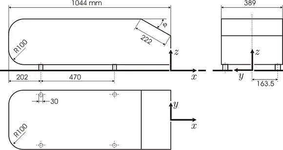
The flow for this model is turbulent, which is based on the Reynolds number determined by the body length and inlet velocity. The simulation solves for the turbulent kinetic energy in addition to the velocity field. For this simulation, we need a larger mesh size than what is usually common to resolve the turbulent flow. More specifically, we use a finer mesh downstream of the model to capture the wake zone.
The flow for this model is turbulent, which is based on the Reynolds number determined by the body length and inlet velocity. The simulation solves for the turbulent kinetic energy and dissipation in addition to the velocity and pressure fields.
Need For the study of the dynamics of fluid over a Body
Any body moving in any kind of fluid experiences different resistances depending on the speed,shape ,surface smoothness and velocity of the body.The Automobiles,Aircrafts etc move through a ocean of fluid called air.Thus experiences resistance to move.One of the major resistances offered by fluid is Drag.The Amount of energy a automobile utilises to overcome these resistances are significant(about 10-15%).Because of this the fuel consumption will be increase .Thus there is a need for engineers to study about the dynamics of fluid around the body and try To reduce drag forces to the maximum extent.
There are many factors that affect the Drag forces Viscosity,velocity and shape of the body.So to study and perform experiments on the behaviour of air on the Automobiles Ahmed body is devloped.The real world simulations are performed on the Ahmed body it is similar replica of the cars.As it is difficult to perform simulations on the Realworld cars At late 80's Ahmed body is devloped.
Ahmed's body and its importance.
Ahmed body is very much useful in predicting the most aerodynamic features that act on the automobile.The Ahmed body is a model very useful in the automotive industry for validating simulation tools. The Ahmed body shape is simple model, while maintaining car-like geometry features.This is a bluff body though we cant be able to predict the flow seperation effects in a useful way.
significance of the point of separation.
A fluid flowing over a body tries to attach to the body this effect is called coanda effect.When a fluid flow over a body it devlop a boundary layer which is actually a gradient of velocity.The topmost layer in the boundary layer velocity is very close to the free flow velocity.As the boundary layer is fully devloped the boundary layer seperation takes place.
The point at which the fluid flow seperates from the body is called Point of seperation.A wake region is devloped after the flow seperation.In this region vortices are formed and the pressure will be negative pressure which increases the drag on the body.For a laminar flow over a sphere occurs at`80^o`but for a turbulent flow flow seperation occurs after `120^0`.So it is important to keep the flow attached to the body as long as possible.So we need to delay the point of seperation to the maximum extent to reduce the drag on the vehicle.
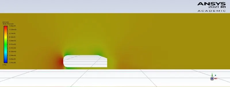
Reason for negative pressure in the wake region
There are two types of drag pressure drag and friction drag,Pressure drag occurs due to difference in the pressure in the front and rear of an object.Pressure drag is mostly significant over a bluff body.The pressure drag increases with the flow seperation.The flow seperation occurs when the boundary layer detaches from the body thus creating the wake region behind.Wake region is a region where there are recirculating turbulent flow.Thus creating a low pressure region.Another reason is When a body is moving through a fluid it displaces the fluid before it and similarly there will be a region behind the body where there is no fluid.This occurs when the body moves very fast and the time is not sufficient for the fluid to displace the emptiness.This emptiness behind the body is the wake region with negative pressure.
Problem solving and modelling approach:
- Importing Ahmed body model into space claim
- Creating enclosures over the body
- Splittig the body as the body is symmetrical
- Interference is removed between the outer and inner enclosure
- Suppression of ahmed body for physics
- chech share topology is set to share
- Perform Meshing
- pre processing (seeting up the parameters and solvers,def for reports needed)
- Initialize and run fluent solver
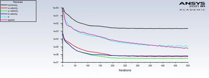
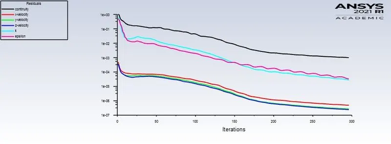
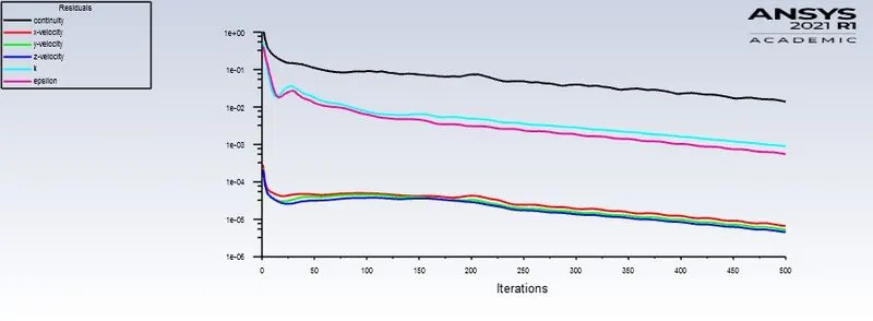
- check for the convergence
- Post processing in the cfd post
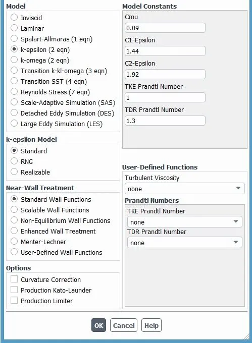
The flow in this simulation is turbulent flow so k-epsilon based sover is used.
In the following report 3 cases of refined meshes are compared And a case with no refinement
Steps in the simulation setup:
Geometry:
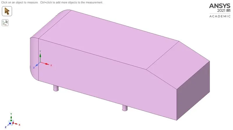
This is the geometry used for the simulation.
Enclosure creation
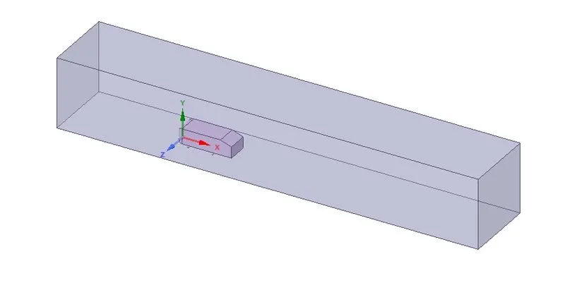
To get the results in a confined space enclosure is created around the body
An enclosure with dimensions left,right,top,bottom from the side view are 2m,5m,1m and 0m respectively.From the front view left and right distances of 0.5m each.
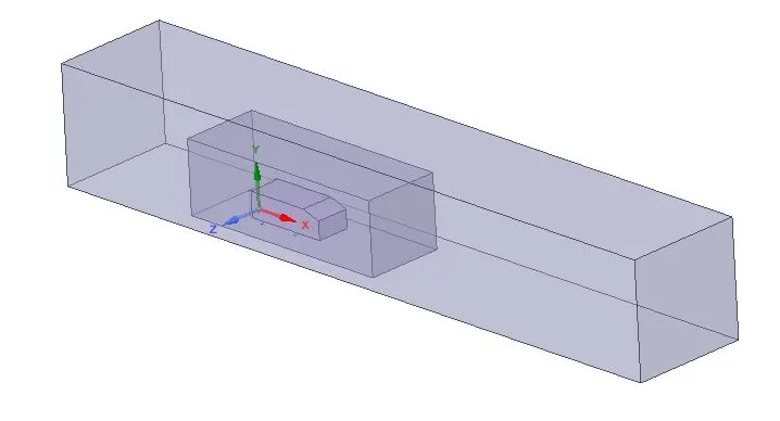
Smaller enclosure
This enclosure is to create the fine mesh close to the body which where the dynamics are significant.This also reduce the number of elements as we create fine mesh only in the smaller enclosure.The distance for the boundaries of the enclosure 0.5m from left and top,1m from right and 0m from bottom of the body.
Spliting :
As the body is symmetrical the body is split into half using the split body tool.
This Reduces the computational time And also we can refine the mesh further more as half of the elements were removed.After that we need to make sure that shate topology is set to share.
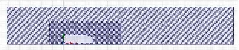
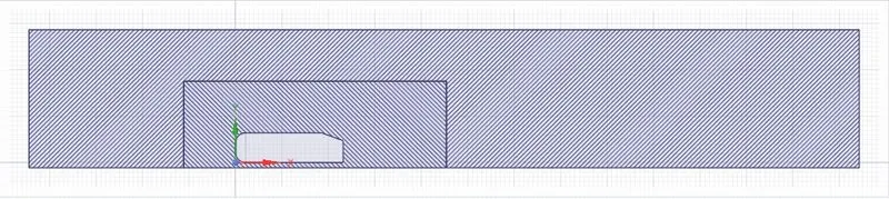
There will be interference in the enclosure we need to remove the interference by clicking on the interference option
With interference
Without interference
Meshing:
In this Meshing element type, element size are defined.
Mesh type:Multizone mesh
Inflation
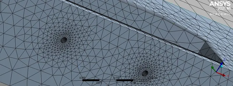
Inflation layers are created for better understanding of air flow close to the body.Inflation layer is alayer that follows the body at a distance.
Calculation for inflation layer
Calculation of first layer thickness
There are formulas also to calculate first layer thickness we used Y+ calculator for finding the first layer thickness.
The website used for first layer thickness
The fist layer thickness we got is 5.12 mm
“Total Thickness” option in the Inflation settings is selected and maximum thickness of the boundary layer mesh is giver.
Formula to calculate total thickness is `S_n=(a_1(r^n-1))/(r^n-1)`
r is the growth rate
Total thickness we got is 50.84
Setup:
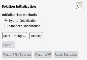
Pressure based solver is used with a simple scheme and the initialization is hybrid
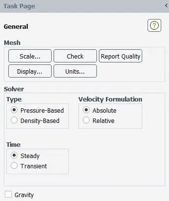
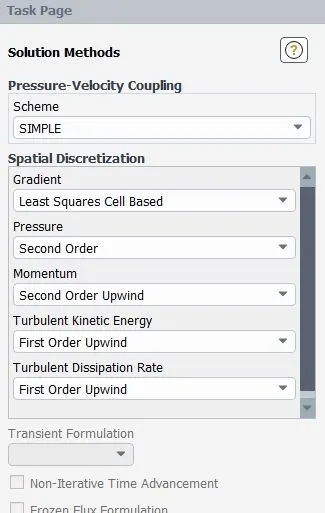
Model k-epsilon is used as the flow is tutbulent flow
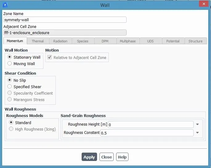
Symmety wall boundary condition set to no slip condition
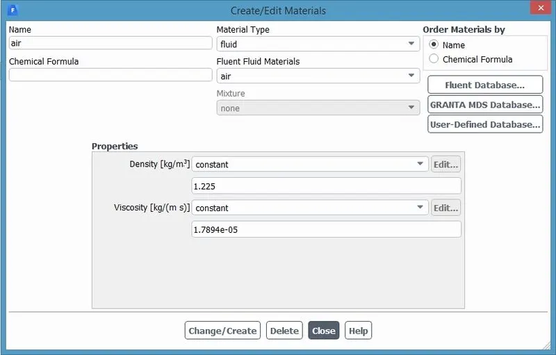
Fluid used for simulation is air
Results:
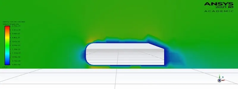
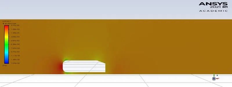
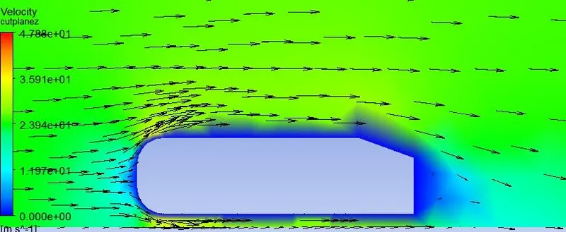
In the Cfd post processing we can visualize the vectors around the body
Baseline Mesh:
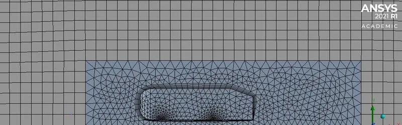
This Mesh is created With the Mesh size determined by the mesher.The plots we got are very With vague detailing and not useful
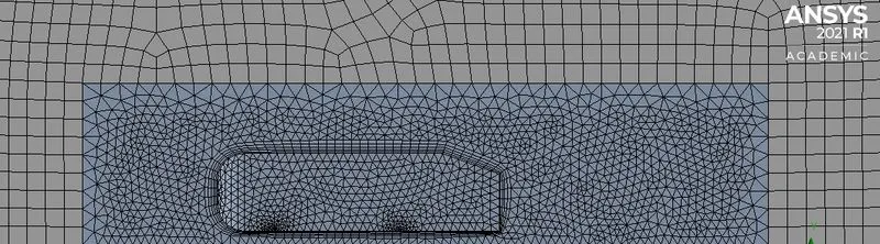
Mesh:

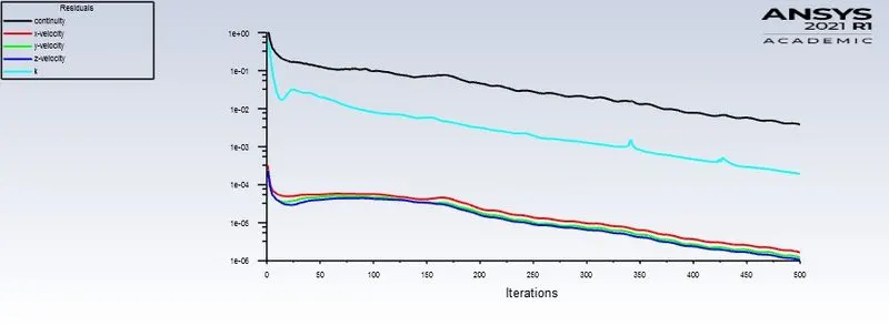
Residuals:
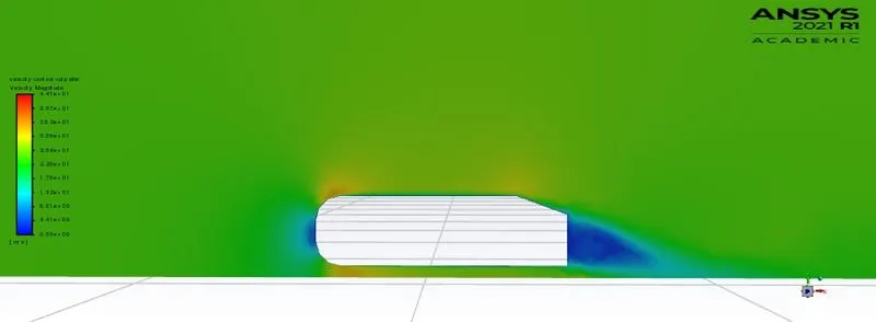
Velocity contour
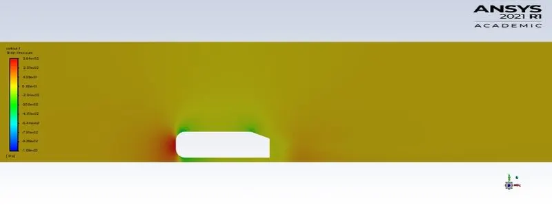
Pressure contour
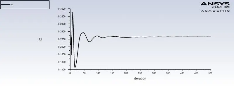
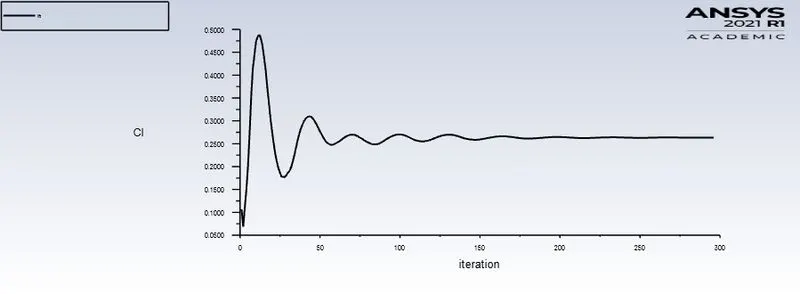
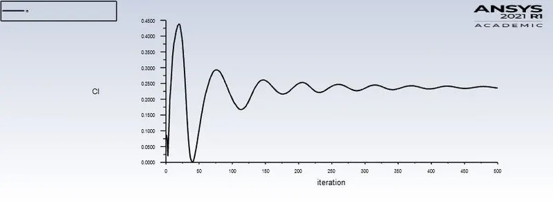
Lift
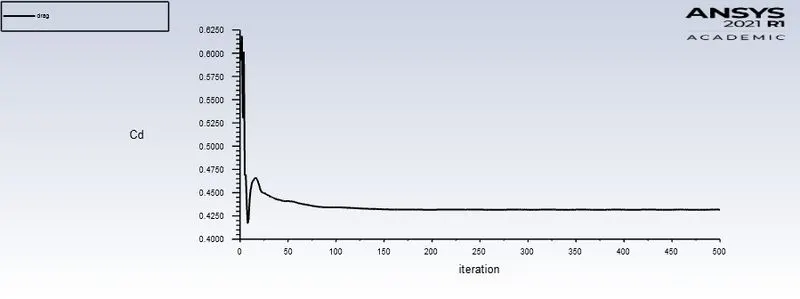
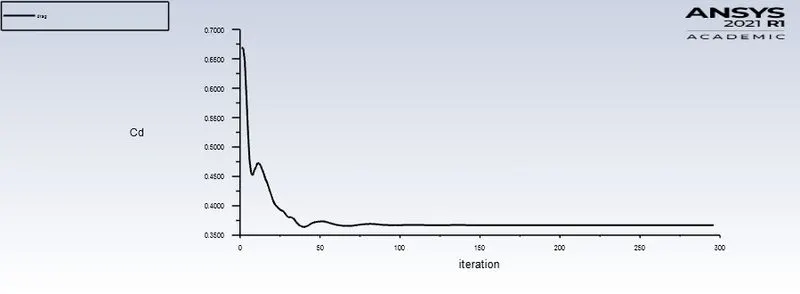
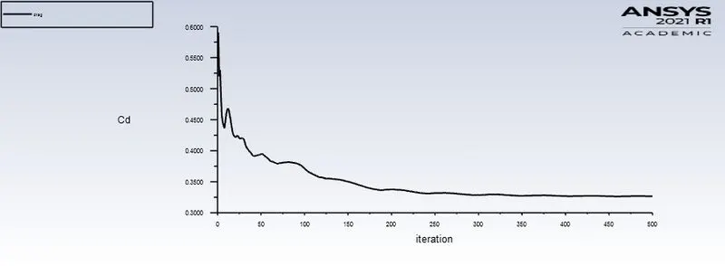
Drag
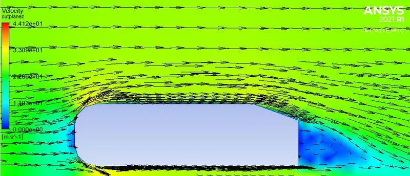
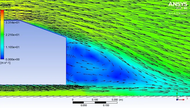
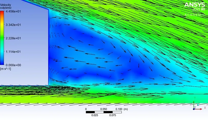
Vectors
Case
No of elements 68,386
element size in the outer enclosure 0.1m
element size in the inner enclosure 0.05m
velocity -25m/s
Y+ 300
Mesh
Residuals
Velocity contour
Pressure contour
Lift
Drag
Vector
Case
No of elements 2,16,681
element size in the outer enclosure 0.07m
element size in the inner enclosure 0.03m
velocity -25m/s
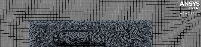
Mesh
Residuals
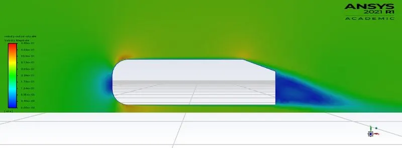
Velocity contour
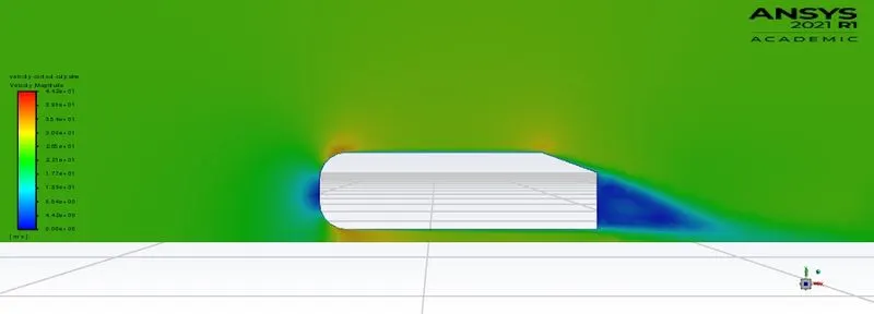
pressure contour
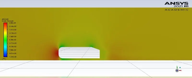
Lift
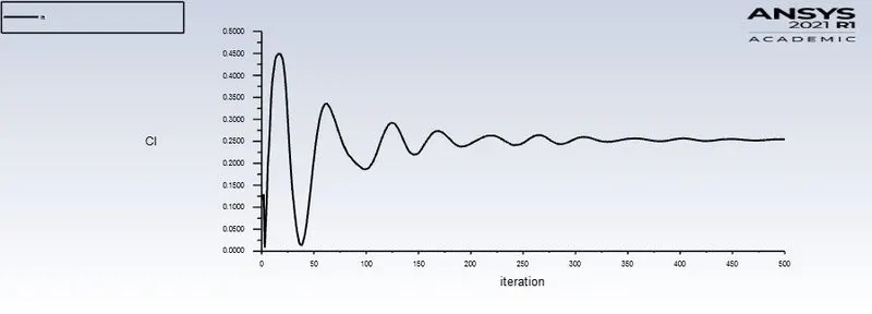
Drag
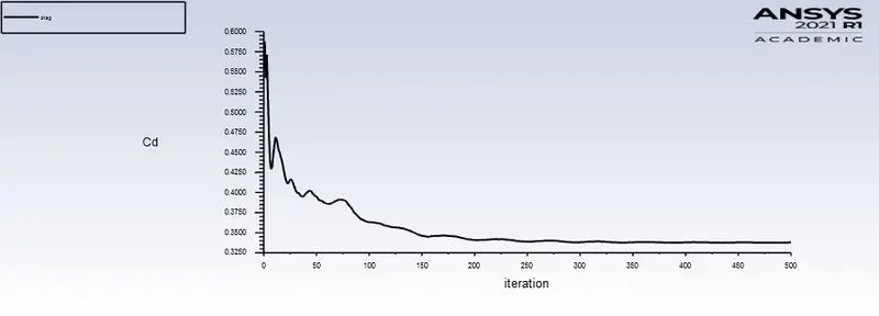
Vectors
Case
No of elements 3,44,665
element size in the outer enclosure 0.065m
element size in the inner enclosure 0.025m
velocity -25m/s
Mesh
Residuals
Velocity contour
Pressure contour
Lift
Drag
Vector plot
Drag coefficients for different quality of meshes
| No of elements | Nodes | Drag coefficient |
| 42,586 | 8585 | 0.435 |
| 68,389 | 26,511 | 0.366 |
| 2,16,681 | 67,304 | 0.338 |
| 3,44,665 | 93,635 | 0.327 |
Conclusion:
- It is evidant that the baseline mesh gives results and plots that are vague.
- Refining the mesh gives results close to the proposed drag.
- With the refined mesh we can be able to vizualise aerodynamics around the body clearly.As the Mesh is further refined gives more convincing plots and results.
- Although Refining Mesh to very finess makes the computational time very large.Computational time sometimes may vary exponentially with the refinement of the Mesh.So we must be able to select the mesh size according to the problem which is optimized.
- More refined mesh gives more detaling but it requires more computational power and licensing.
- With the refined mesh we are able to vizualise the velocity vectors in the wake region (vortices formation).
- Refined mesh produces accurate results.