Week 3 - External flow simulation over an Ahmed body.
Assignment- simulation of Ahmed body (Ansys Fluent)
Aim-perform simulation of Ahmed body and also perform grid independency test and also provide darg and lift coefficient values for each case
- Ahmed body and its importance
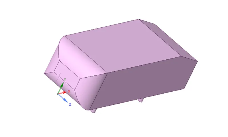
Ahmed body and Importance of Ahmed body- if you see the Ahmed model then we can easily say that it is model like car. Ahmed body is a generic car body (a basic car model). the airflow around the Ahmed body captures essential flow features around an automobile.it is simple shape, Ahmed body allows us to capture features (characteristics features) that are relevant to bodies in the automobile industry.
Engineer who works in vehicle aerodynamic use Ahmed body to validate their numerical model because the experimental data from wind tunnel testing is available for Ahmed body. If any numerical model of car validates then it is used to design new model of car
- Ahmed Model for this simulation-
Simulation case:
Case 1:
outer encloser-element size-100 mm
Inner encloser-element size-50mm
Case 2:
outer encloser-element size-90 mm
Inner encloser-element size-45mm
Case 3:
outer encloser-element size-80 mm
Inner encloser-element size-40mm
How to find total thickness by considering Y+
- Re=ρVL/µ
V=velocity
L=characteristics length
Re=Reynold number
µ=kinematic viscosity
- Cf=0.05*Re^ -0.2
Cf=coefficient of skin friction
- Tw=(Cf*ρ*V^2)/2
Tw =wall shear stress
- Vt= (Tw/ ρ) ^0.2
- Y+=(ρ*y*Vt)/ µ
y=first layer thickness
- total thickness=y*^(layer-1)
***note-for k-epsilon model- standard function Y+ values is between 30-300
after putting all values in above formulas, we get your total thickness
point of separations-
- It is defined as forward and reverse flow in the layer very close to wall, at the point of separation wall shear stress equal to 0
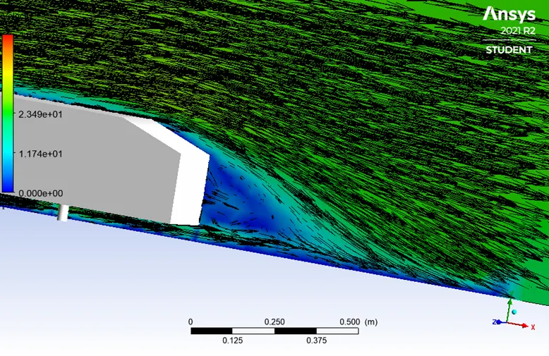
- separation occurs due to an adverse pressure gradient encountered as the flow expands, causing an extended region of separated flow
- the part of the flow that separates the recirculating flow and the flow through central region of duct is called dividing stream line
Modelling approach for this simulation and steps in the simulation
- geometry
- Mesh
- Setup
- Solution
- Results
Case 1: outer encloser-element size-100 mm
Inner encloser-element size-50mm
- Geometry- 3d model is imported to spaceclaim.to simulate flow over Ahmed body encloser was created surrounding the Ahmed body. For refined mesh near surface of the body an inner encloser was created
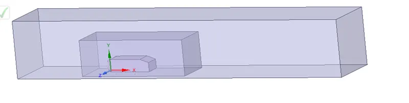
- Mesh-
outer encloser-element size-100 mm
Inner encloser-element size-50mm
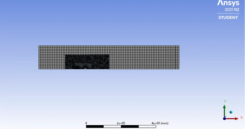
No. of elements in mesh-192759
Inflation layer is generated in order to capture detailed physics near the wall
- Set up-
Slover type-pressure Based Solver
Time-Steady state
Model-viscous k-epsilon turbulant model-standard
Energy-turn off
Boundary condition- inlet velocity=25m/s
Material properties- Air density-1.225kg/m^3
Method -coupled
Intilization-hybrid inilization
- Solution and results-
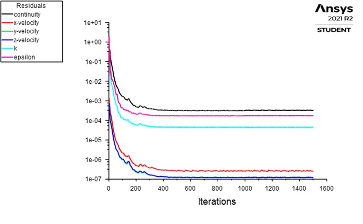
In residual plot We assume that after 700 itreation solution is converged because there is not observe the any changes in residual plot
Drag coefficient
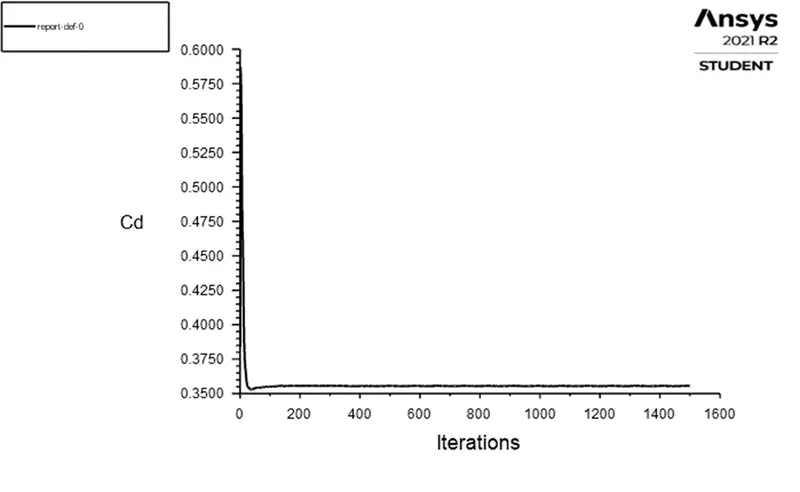
Drag coefficient=0.3555
Lift coefficient
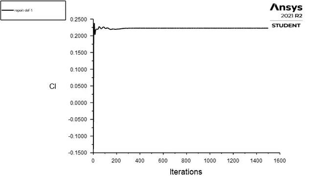
Lift coefficient=0.2228
Vector plot
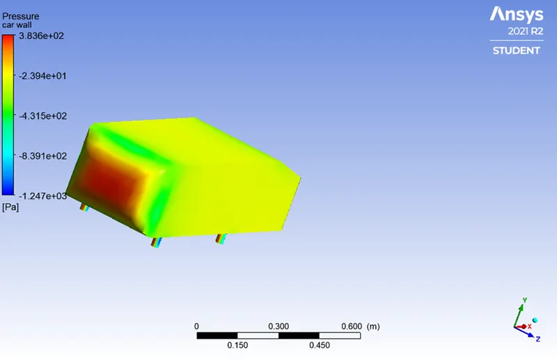
Pressure at car wall
Velocity contour
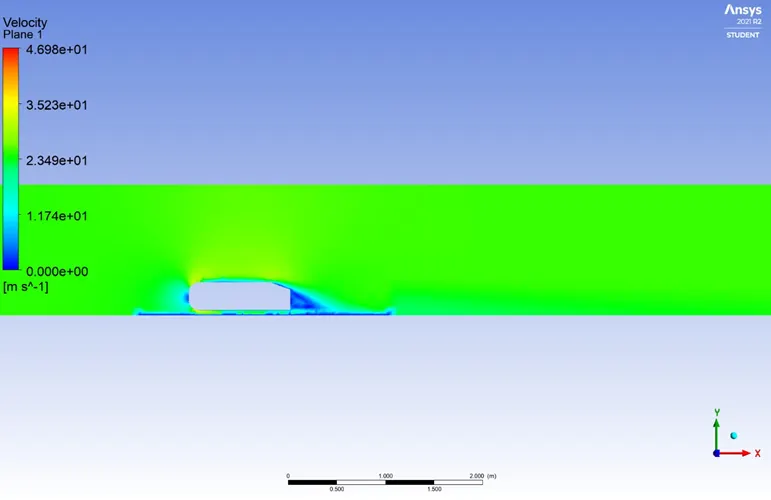
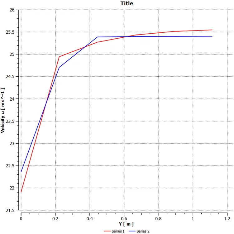
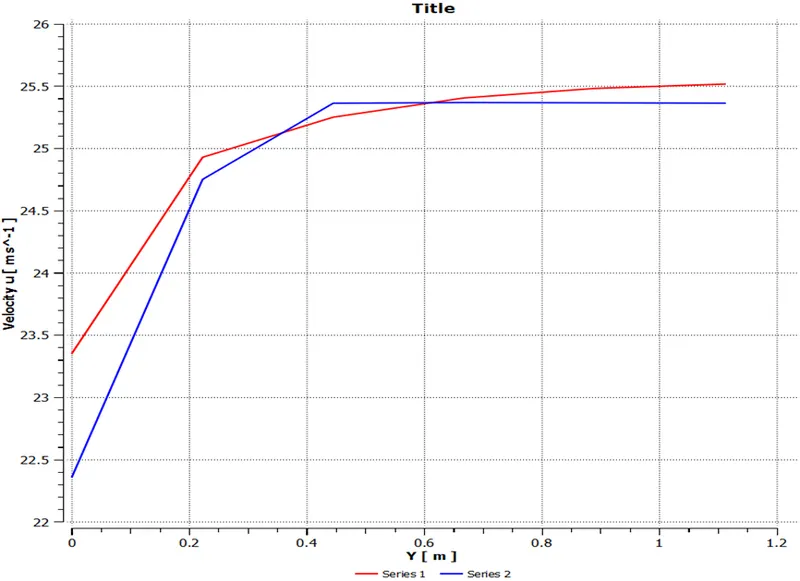
Chart-velocity u
Line 2= point1(3 0 0), point2(3 2 0)
Line 1=point1(2 0 0), point2(2 2 0)
Case 2
- Mesh
outer encloser-element size-90 mm
Inner encloser-element size-45mm
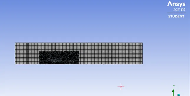
No. of elements in mesh-242018
Inflation layer is generated in order to capture detailed physics near the wall
- Set up-
Slover type-pressure Based Solver
Time-Steady state
Model-viscous k-epsilon turbulant model-standard
Energy-turn off
Boundary condition- inlet velocity=25m/s
Material properties- Air density-1.225kg/m^3
Method -coupled
Intilization-hybrid inilization
- Solution and results-
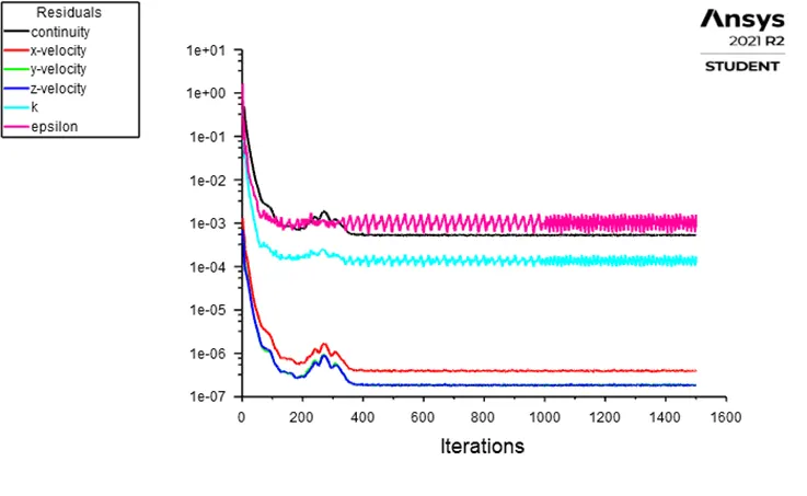
In residual plot We assume that after 1100 itreation solution is converged because there is not observe the any changes in residual plot
Drag coefficient
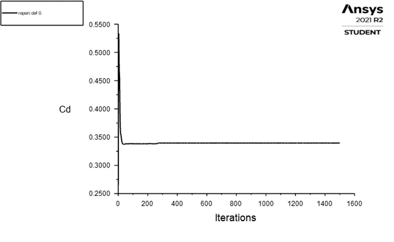
Drag coefficient=0.3395
Lift coefficient
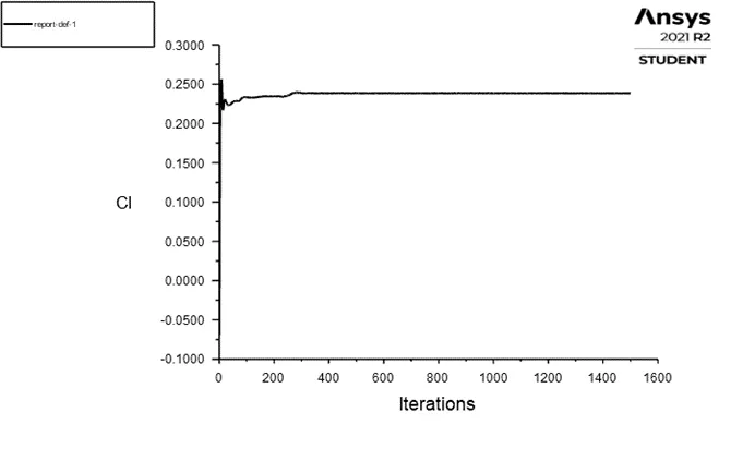
Lift coefficient=0.23855
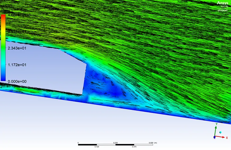
Vector plot
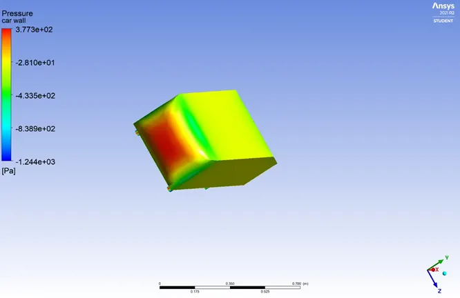
Pressure at car wall
Velocity contour
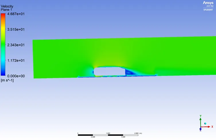
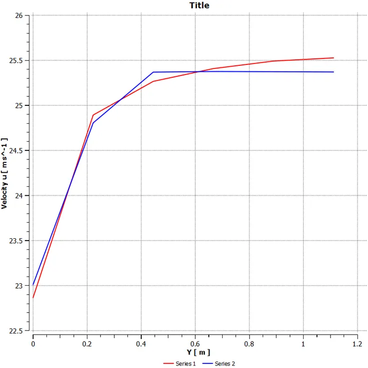
Chart-velocity u
Line 2= point1(3 0 0), point2(3 2 0)
Line 1=point1(2 0 0), point2(2 2 0)
Case 3
- Mesh
outer encloser-element size-80 mm
Inner encloser-element size-40mm
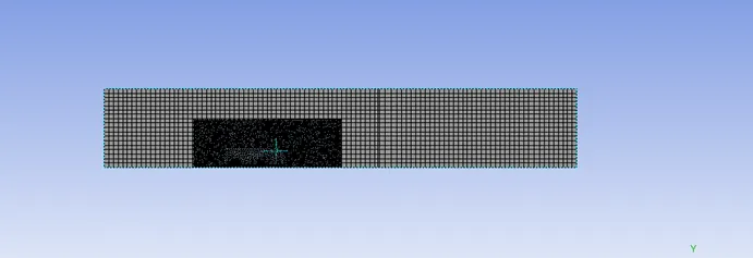
No. of elements in mesh-314065
Inflation layer is generated in order to capture detailed physics near the wall
- Set up-
Slover type-pressure Based Solver
Time-Steady state
Model-viscous k-epsilon turbulant model-standard
Energy-turn off
Boundary condition- inlet velocity=25m/s
Material properties- Air density-1.225kg/m^3
Method -coupled
Intilization-hybrid inilization
- Solution and results-
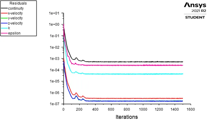
In residual plot We assume that after 1200-1300itreation solution is converged because there is not observe the any changes in residual plot
Drag coefficient
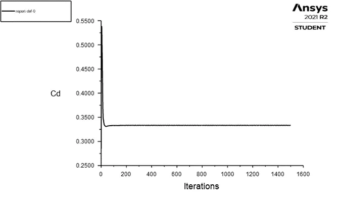
Drag coefficient=0.33335
Lift coefficient
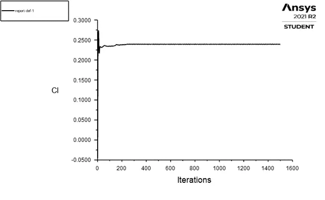
Lift coefficient=0.23902
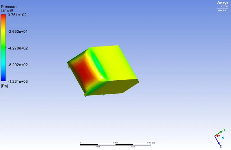
Pressure at car wall
Vector plot
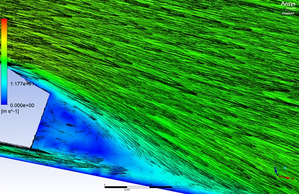
Velocity contour
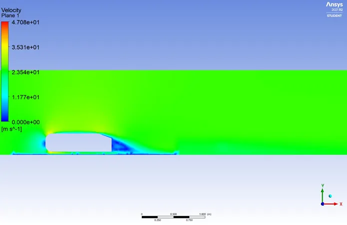
Chart-velocity u
Line 2= point1(3 0 0), point2(3 2 0)
Line 1=point1(2 0 0), point2(2 2 0)
- Why pressure goes negative on ahmed body
1.the air strikes body front at higher velocity because of that kinetic energy converted to pressure energy.so the pressure is highest at front
2.As the air passes over the ahmed body the velocity is accelerated.then maintain the flow contiunity the pressure becomes lower and goes to negative
3.pressure go negative because adverse pressure gradient due to flow speration.in fluid dynamic adverse pressure gradient occures when static pressure increase in direction of flow
Results and conclusion
- Grid independency test results
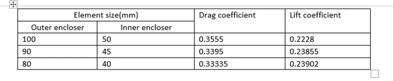
- Expected results= drag coefficient is 0.33 so, we conclude that our simulation is validate
- As mesh is finer the wake region seen clearly