Week 3 - External flow simulation over an Ahmed body.
AIM- To refine the mesh around the body and perform grid independence test by varying the mesh size and record the change in drag.
AHMED BODY AND ITS IMPORTANCE
Ahmed body was first created by S.R Ahmed in his research "Some salient features of the time averaged ground vehicle wake" in 1984, since then it is considered as a standard body for the study of aerodynamic simulation tools.Dealing with the depleting energy resources that has become an important environmental concern, the need to improve fuel effenciency of vehicles has raised, the one possible solution to tackle this issue is to reduce the drag, which will consequently result in improved fuel effeciency,To reduce aerodynamic drag effectively, we need a comprehensive understanding of the flow structure around the vehicle.Hence, Ahmed body is used as a standard car body for validating industrial simulations.
Ahmed body is a generic car body with an inclined back that has different angles between 0-40 degrees, it is used as a test case for simulating aerodynamics and flow characteristics over a car model.
PROCEDURE-
1.Ahmed body is loaded and enclosed in a rectangular enclosure at the front end a length of 2m is provided and for the rear end 5m, similarly 1m for top and 0 m for bottom and width provided is 0.5 m on ether sides of the body.
2.The body is then split into half to carryout the further simulaton,this is possible due to the symmetry of the model.
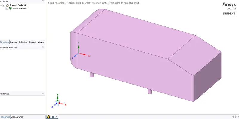
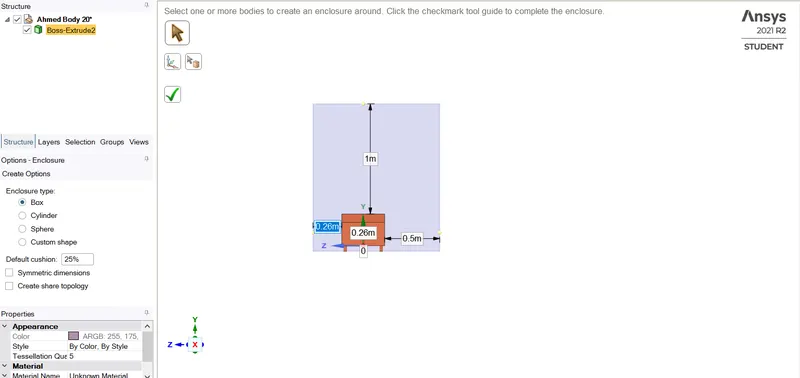
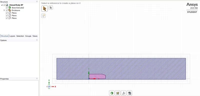
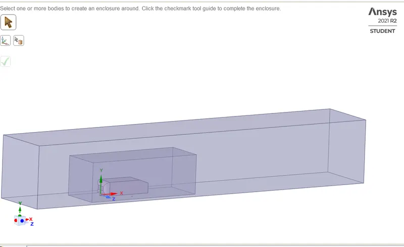
3.For the refined case the model is enclosed within two enclosures.
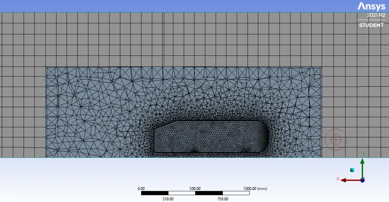
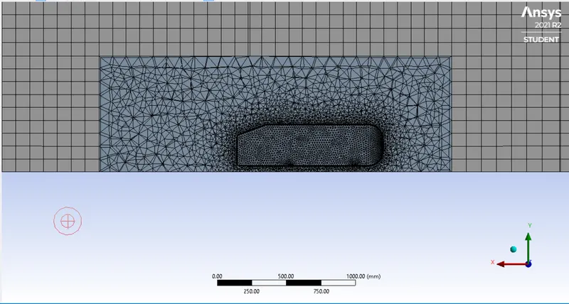
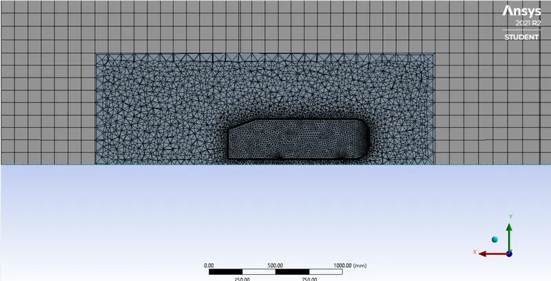
4.Later in meshing stage, different mesh sizes are defined as required for the grid dependence test, inflation layers are provided and height of the inflation layers is calculated from reynold's number and hexahedral mesh is generated with the ahmed body being suppressed for physics allowing the mesh to be generated only outside the ahmed body and also faces are named and faces comprising the enclosure are hidden and the car model is selected using box selection and then named.
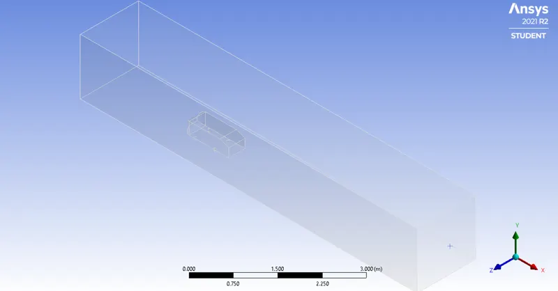
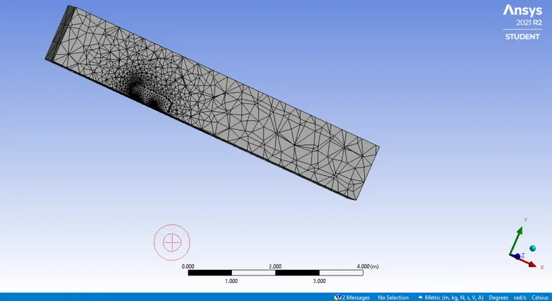
5.In the setup stage, density based solver is selected and in the physics velocity is defined as 25m/s with air as the flow fluid having density of 1.225kg/m3 and dynamic viscosity of 1.7894e-05kg/m-s.
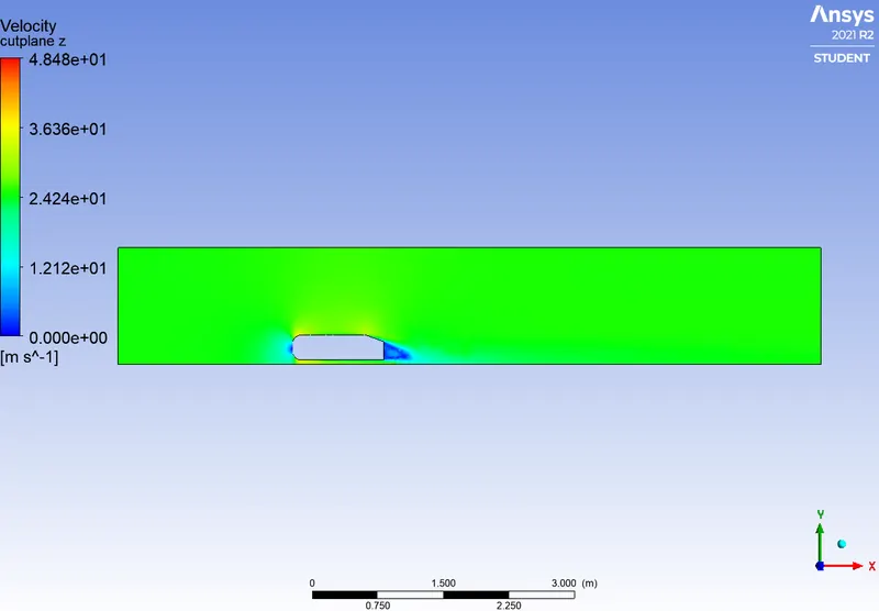
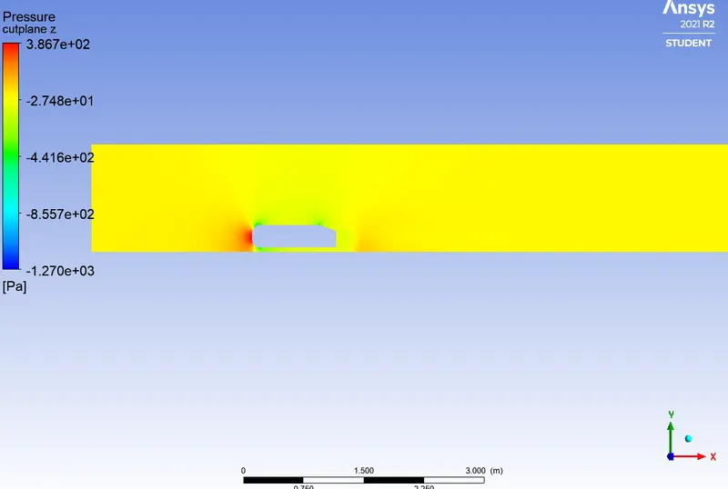
6.Then plots for drag,velocity contour,pressure contour are plotted and the simulation is performed.
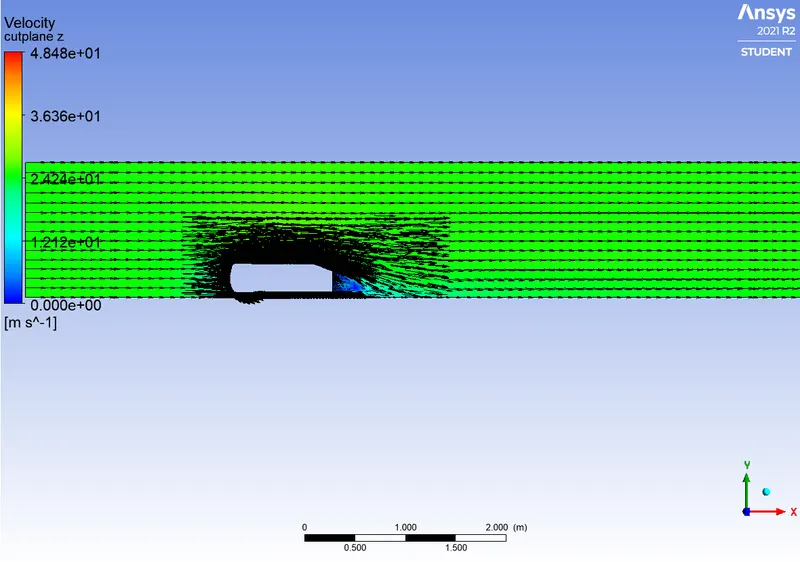
CASE 1
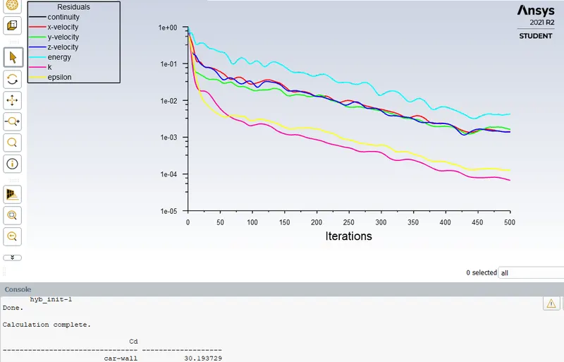
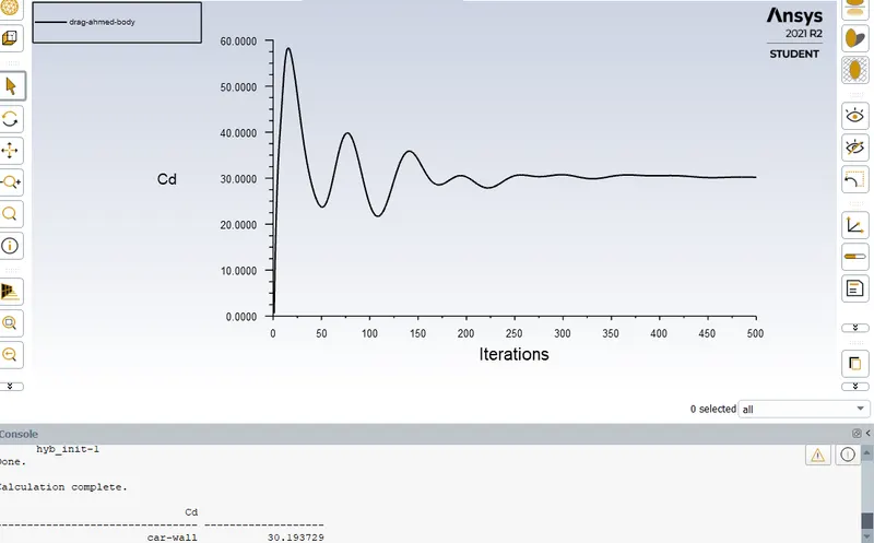
Un-refined mesh
Mesh size= 413.6mm
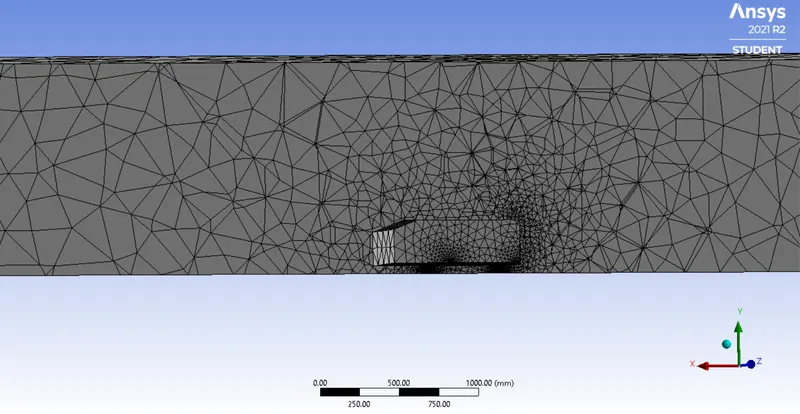
CASE 2
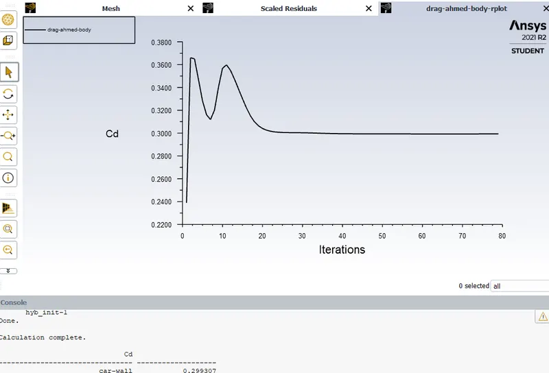
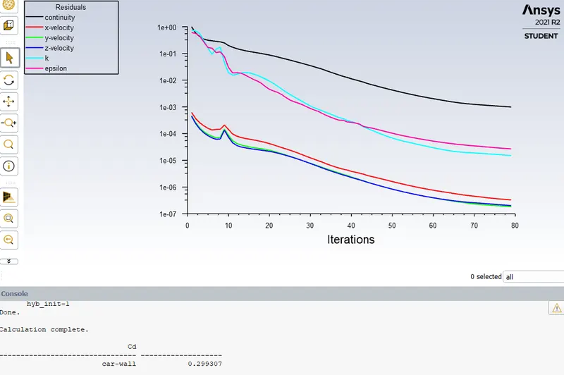
Mesh size= 100mm
Y+= 100
CASE 3
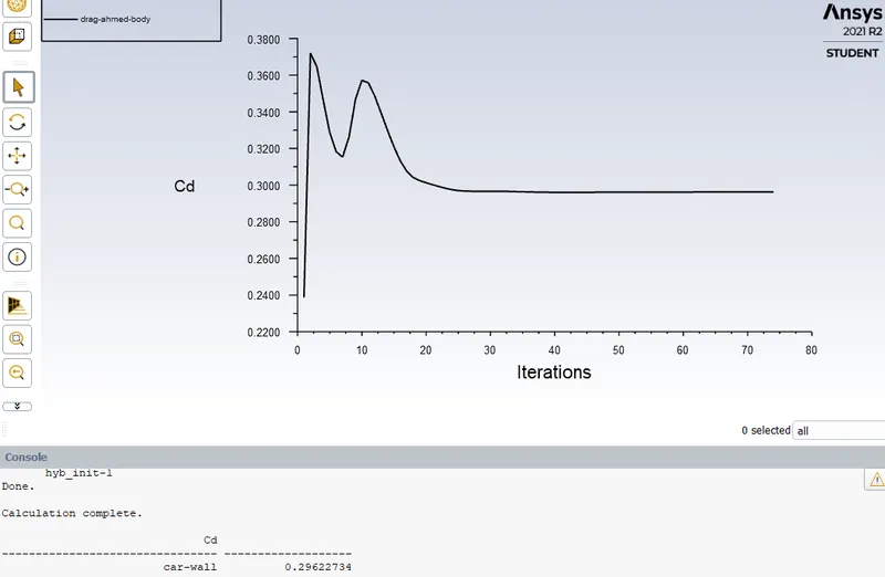
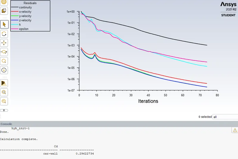
Mesh size= 75mm
Y+= 75
CASE 4
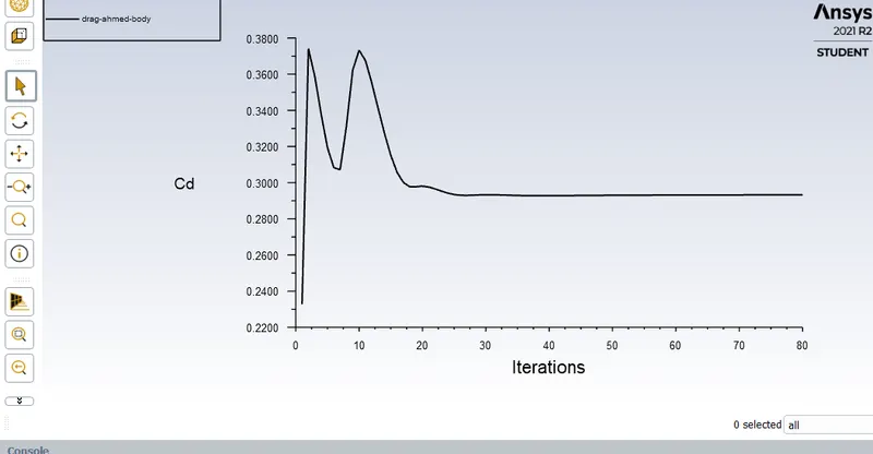
Mesh size= 50mm
Y+= 50mm
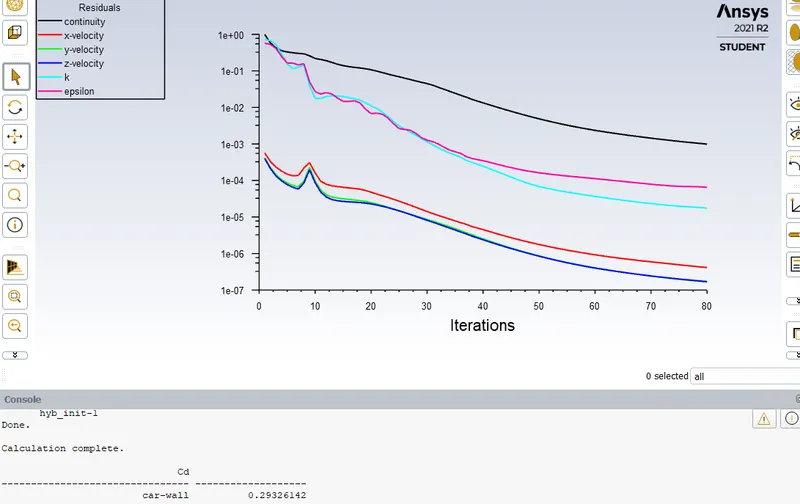
RESULTS-
| MESH SIZE | VALUE OF Y+ | CO-EFFECIENT OF DRAG |
| 413.6 | nil | 30.193729 |
| 100 | 100 | 0.299307 |
| 75 | 75 | 0.29622734 |
| 50 | 50 | 0.29326142 |
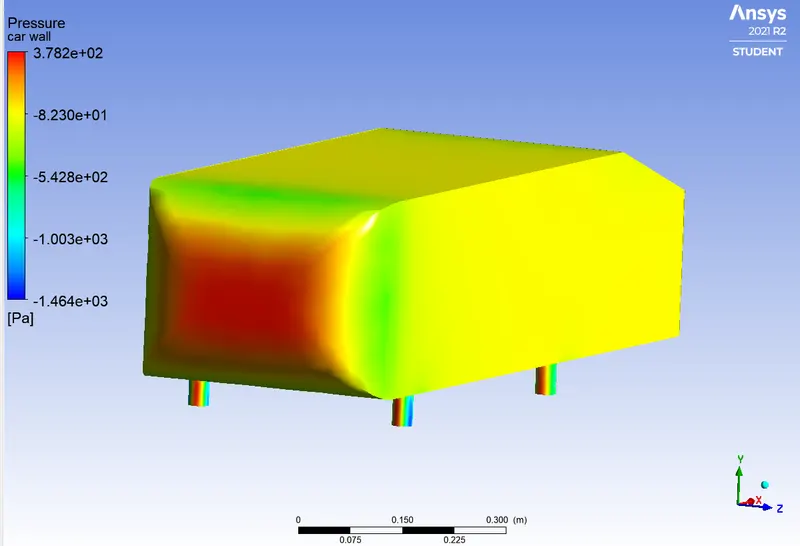
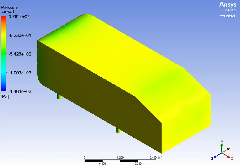
NEGATIVE PRESSURE AT THE WAKE REGION
In the wake region the value of static pressure goes negative due to re-circulating flow behind the body resulting in disturbances in the fluid flow pattern which consequently leads to loss of momentum causing drag that extends far behind the ahmed body.The air turns downwards around the sharp ends of the car, travelling from hgh pressure region under the car to low pressure region on the top of the car, at the wake region and hence, collides with the moving low pressure air.
CONCLUSION
The simulation is grid independent as the mesh becomes finer and the Y+ value is varied within an appropriate range it is observed that the accuracy of results increases.