Week - 3 Drop test Challenge
Introduction : Drop test challenge.
A drop test is a test designed to examine the structural integrity of a product.
Drop tests usually involve an object being dropped from a predefined height onto a second object or surface. The object being tested can be either the dropped object or the object/surface that an object is being dropped on to.
Analysis :
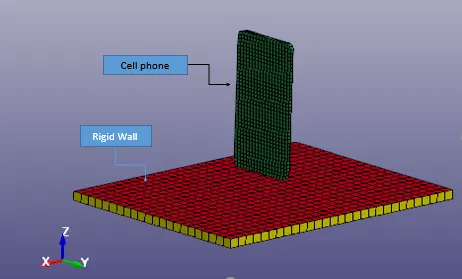
- Here we will see the Drop Test of simplified model of Cellphone on the concrete Ground.
- There will be free fall of a Cellphone on the ground, which generally is made of concrete.
- So we will take the material for Cellphone as Aluminium and for Rigid body as concrete.
- Here the reason for taking the concrete as rigid body is to see the effect like phone drops on the floor at home.
Geometry:
Material :
Cell phone :
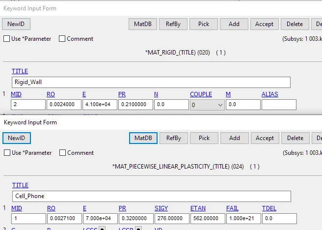
Material Model : PIECEWISE_LINEAR_PLASTICITY (024)
Density : 0.00271g/`mm^3`
Elastic Modulus = 70000 Mpa.
Poisson's ratio = 0.32
Tensile Yield strength : 276 Mpa
Rigid Wall:
Material Model : RIGID (020)
Density: 0.0024000gm/`mm^3`
Elastic Modulus: 41000Mpa
Poisson's ratio : 0.21
Procedure :
- Modelling and Meshing of the parts can be done in any pre-processor software such as Hypermesh, Ansa etc.
- then the final modelled file is then imported in LS-Dyna where we will be applying boundary condition and other control cards.
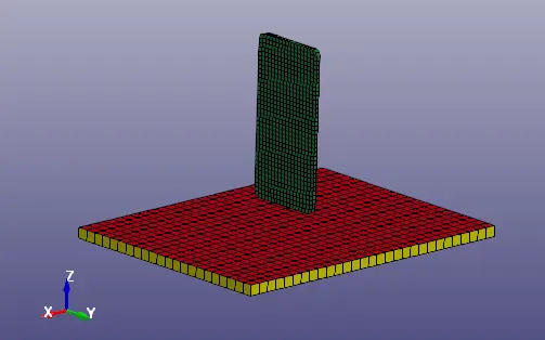
- we have to create different cards necessary for analysis.
Boundary:
- Create boundary condition for Rigid Wall as shown in below image.
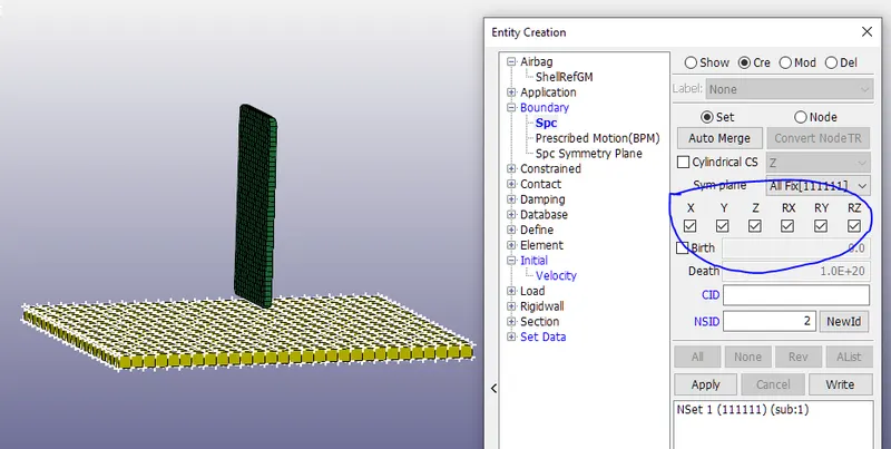
- As shown in above image, we can see that 'SPC' single point constrain is applied to rigid wall with all DOF being constrained.
Initial Velocity :
- Since we are performing Drop Test, the phone is droped with any froced acceleration.
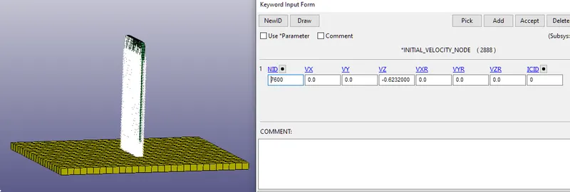
- Free fall of the phone from 19.8mm distance in z-direction, will be 0.6232mm/ms.
- We have to create initial velocity with value -0.6232mm/ms in negative z-direction, as shown in below image.
Section:
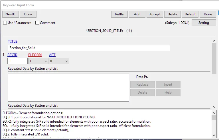
- We have to create Section for Solid elements .
- Here element formulation is set to 1 . which is Constant stress solid element.
- this section needs to be assigned to both cell phone and rigid wall.
Material :
- Creating material card for the cell phone and Rigid wall
- Assigning these material card to their respective parts.
Contact :
- For the reaction behaviour of the interface, we have to create Contact interface between Phone and Rigid Wall as given below.
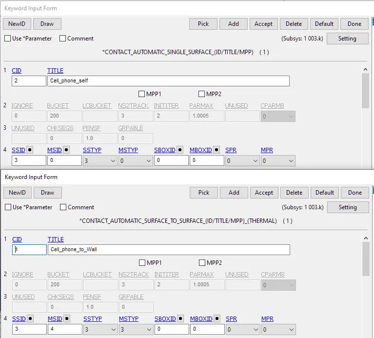
- Create ' AUTOMATIC_SURFACE_TO_SURFACE ' for contact between Cell phone and Rigid Wall.
- Create ' AUTOMATIC _SINGLE _SURFACE ' for self interaction between elements of Phone.
Control:
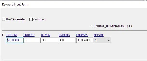
- We have to create card for termination ' CONTROL_TERMINATION ' which helps in termination of simulation period.
- By giving ' ENDTIM ' value we can run simulationa and then terminate it.
- Termination time is given as 50ms.
Database:
- Now after all conditions and termination details, we can generate output request or results what we want from the analysis.
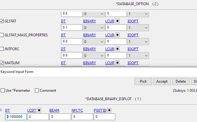
- We have to create cards for the output , we have to select 'BINARY_D3PLOT', 'GLSTAT','MATSUM' from ASCII_ option in the datebase.
- Here we are keeping DT as 0.1 ms such that for every 0.1ms change all the change in the data may be recorded till 50ms.
Calculation :
- After creating all the necessary cards, save the final file with 'k' extension.
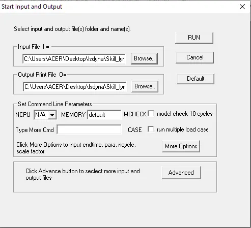
- Run the simulation as per the avialibility of core of the CPU by giving the value of 'NCPU'.
Results :
- Open the binary '.d3plot' file in LS-Prepost for the results.
Effective Von-mises stress :
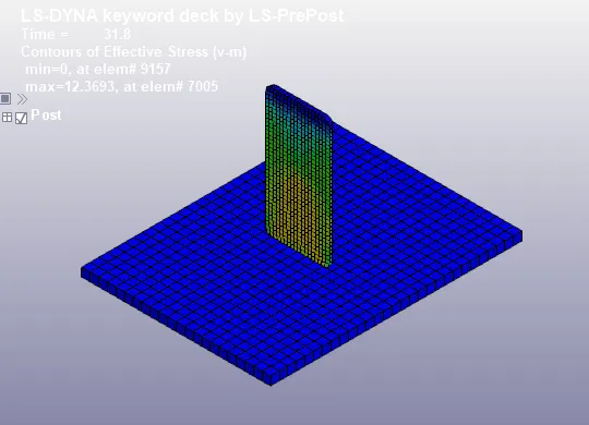
- Max stress is generated is 12.3693 Mpa at 31.8 ms.
Displacement :
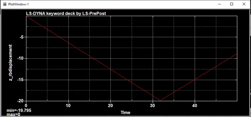
- From below image we can see that the Cell phone has travelled 19.8mm distance .
Global Energies :
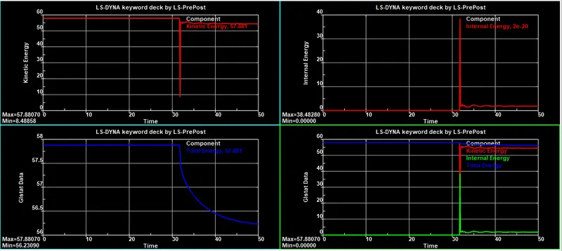
- From the above image, we can say that, when the phone touches the rigid wall, Kinetic energy decreases and internal energy increase at 31.7ms.
- After retraction of phone again Kinetic energy increases and Internal Energy decreases and then both becomes constant.
Conclusion:
By this approach we can say that Material modelling strategy is acceptable for this situation, we need to check with differnet material and their behaviours with different loading condition arriving to correctness of modelling strategy of the simulation, we can even make changes in mesh size, element selection, and contact definition aand check the results, through this simulation we can even improve the design life cycle of the cell phone .