Week - 5 - Modelling Spotwelds
Objective:
- To model a set of spot weld for a given assembly of parts using both 1D beam elements and 3D hex elements.
- To simulate a crash test for a given assembly and compare the results in both cases.
Diliverables:
- Solver deck setup:
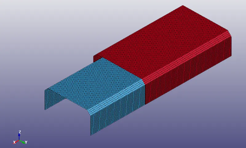
1. Open the given FE model in LS-Prepost, The model consist of 2 parts .
Note : We need to define all the attributes related to the parts as well as create a set of spot welds to connect the two parts, This is done in two ways, first by modelling the welds using 1D beam elements and second by using 3D hex elements, Both the models are subjected to crash test and the results are compared between the two.
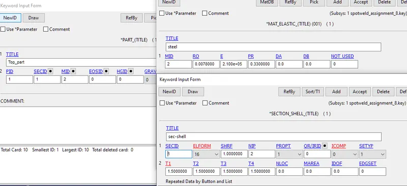
2. Create and assign appropriate materialand section cards to the 2 parts. Note : Here steel is used as the material property to define material card for two parts.
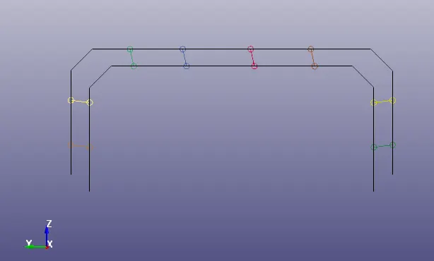
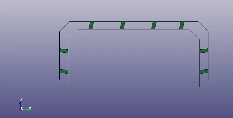
3. Now we need to connect the two parts using spot weld, Here we will model 8 spot weld in a symmetric manner ie, 4 on each side .
Create beam elements using the EleGen option under the mesh button.

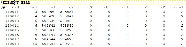
4. Now we have to create and assign material and section cards for the created beam element , ' MAT_SPOTWELD' cards is used for defining the material for the spotweld beam and 'SECTION_BEAM' card is used for defining the section for the beam elements, We will set the TFAIL value as 5ms .
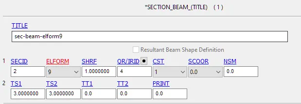
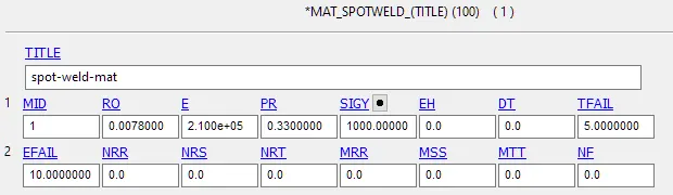
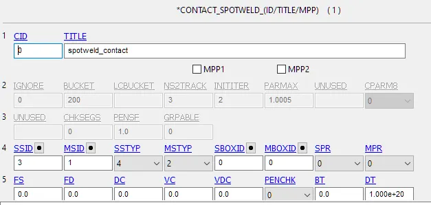
5. Now we need to assign proper contacts to the assembly, To define the contact betwee the beam elements and the two joining parts, we can use the ' *CONTACT_SPOTWELD' card, Keeping the beam elements as slaves and the two brackets as the master segment.
Another contact ' *CONTACT_AUTOMATIC_SINGLE_SURFACE' has to be created for defining the interaction between the brackets during the crash.
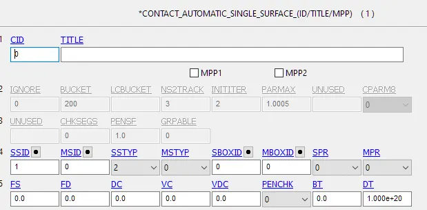
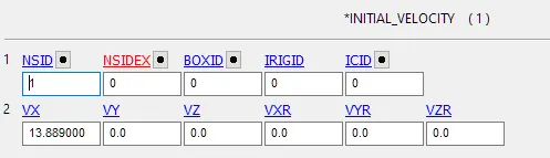
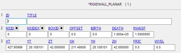
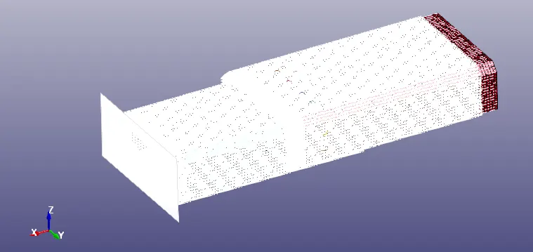
6. Now we need to create a rigid wall and apply an initial velocity to the assembly of parts for simulating the crash event, The '*RIGIDWALL_PLANAR' card is used to define the rigidwall, The wall is created at 15mm away from the bracket, '*INITIAL_VELOCITY' card is used to assign initial velocity of 13.88 mm/ms in global X direction.
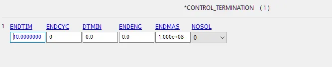
7. We need the simulation to run for 10ms,This can be defined by using '*CONTROL_TERMINATION' card and assigning DT value as 10ms.
8. Now the solver deck has been set up for the 1st case. In the 2nd case, we need to model the spot weld as hexa elements or solid elements, We will use the already created 1st case solver deck and modify it to set the solver deck for 2nd case, We will delete all the beam elements and replace them with hex elements, The hex elements are created using element creation option under ELEtool button, After creating the hexa elements we make use of already existed material card to assigne material to the solid elements, Now delete the existing section cretaed for beam element and create a new section with element formulation 1 and assign it to solids created, Rest everything can be kept as same for both the cases.
Spotweld modelled using Beam elements Spotweld modelled using Hexa solid elements
9. Output request
- We have to create appropriate database card for particular results.
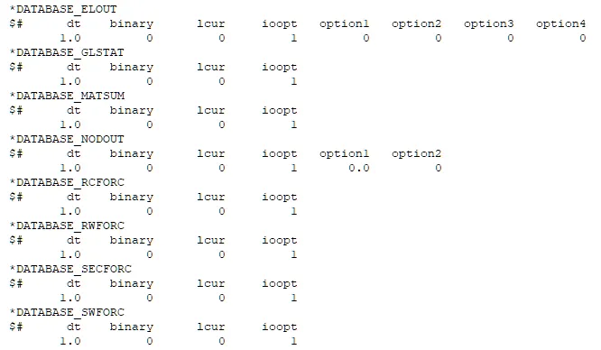
- Use '*DATABASE_ACSII' option card to request for glstat, matsum, sleout, rcforce, rwforce, swforce, notout, and secforc.
The glstat will record all global energy values throughout simulation, the swforc will record the value related to the spotweld, The rwforce will record the forces on the rigidwall, The secforce and nodout will record the values associated with a particular section and node defined using the cards '*DATA_CROSS_SECTION_SET_ID' and '*DATABASE_HISTORY_NODE' respectively.
- Define *DATABASE_CROSS_SECTION_SET_ID and *DATABASE_HISTORY_NODE cards for section and node respectively.
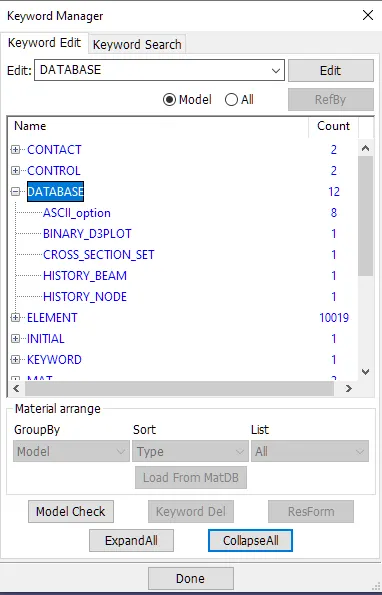
- Create *DATABASE_BINARY_D3PLOT to record the animation of the simulation.

- Make the same output request for both cases.
- Now we have completed the entire solver deck along with output request and our keyword file of both cases are ready for analysis.
- Result and discussion:
- Crash Animation
The animation shows the assembly crashing against the rigid wall
All spot welds fail at 5ms in both cases.
In both cases, on impacting against the wall, the bottom tends to bounce back and this is transfered to top backet via spot welds, After the failure of the spotwelds at 5ms the top bracket is no longer restrained to the bottom part and begins freely move ahead with its inertia.
2. Stress Contour:
Stress contour shows the stresses getting developed on the two brackets.
A greater amount of stress is transfered to the top bracket in 2nd case this may be because of greater stiffness value for the spot welds modelled using hex elements.
3. Strain Contour.
The region around the spotweld can be seen to have strained in case 2 whereas none in case1.
4. Global Energy Plot:
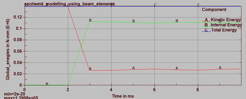
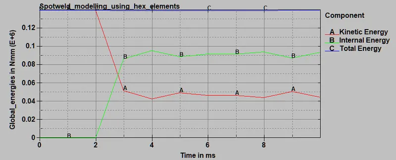
The global energies are ploted for both cases, Total energy remains constant throughout the simulation while kinetic and internal energies changes throughout the crash simulation.
The knetic energy keeps decreasing after the impact correspondingly internal energy increases after the impact, The internal energy reaches peak when the bottom bracket is on the verge of rebounding and then it decreases as it rebounds with some velocity.
5. Spot weld resultant force plot:
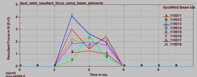
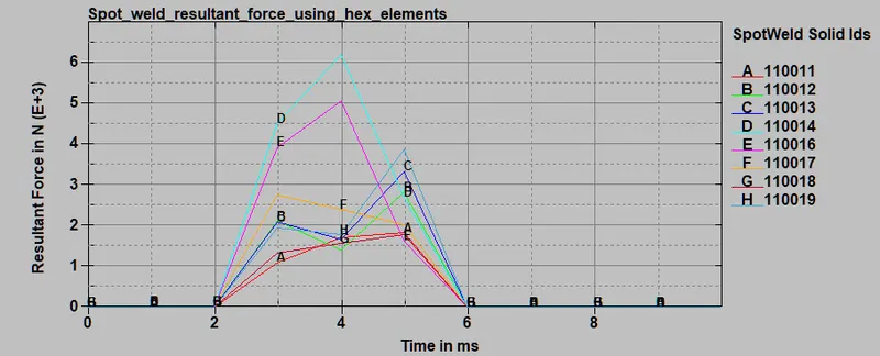
6. Spot weld Axial force plot :
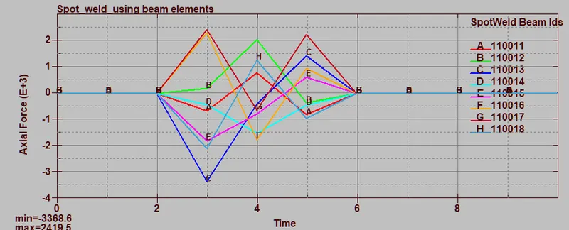
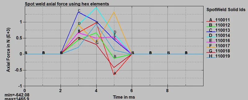
The axial force induced in the spotweld for both cases were plotted using ASCII option, The max Axial force generated in beam spotweld is 2419N where as in Solid element spoptweld is 1465N ,But overall /average axial force is higher in Solid element spotweld since solid element has higher tensile strength it can take higher tensile load.
7. Spot weld Shear force plot :
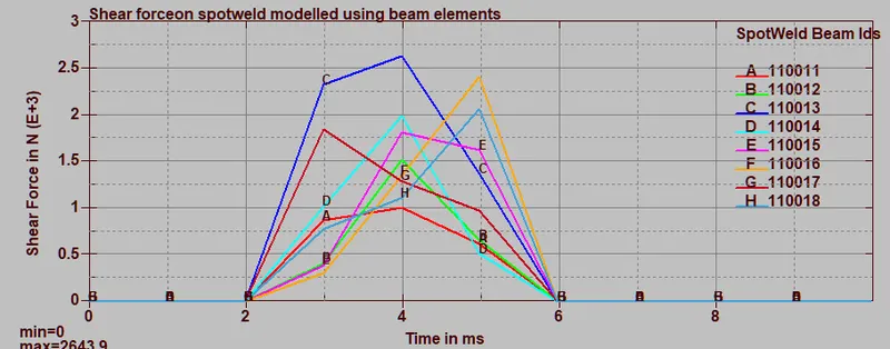
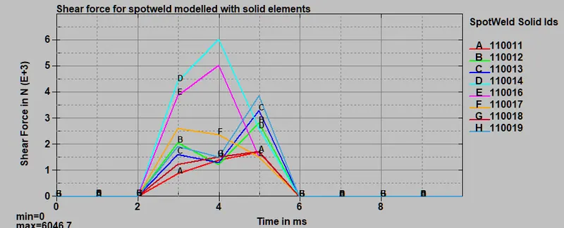
The Max value of shear force in Beam element spot weld is 2643N where as for Solid element spot weld is 6046.7N .
Conclusion:
- Spot welds were modelled using both 1d element as well as 3d elements ,The hex element spot weld transfers more force across the joining parts as a result of higher stiffness.