Week-6 Calculate the Stretch Ratio by comparing the ELFORM (-2,-1,1,2) with Ogden_Material Model.
Aim:
The aim of this project is to compare the different types of element formulation of solid element by tensile test and calculate the stretch value of the model by using hyper-elastic material.
Ogden Material :
Here we are using Ogden material model to simlate the tensile test, This model is a hyper-elastic material which used to describe the Non-linear Stress-Strain behaviour of complex materials such as rubber, Polymers .
Objective :
We need to generate a solid element meshed box having 10mm x 10mm x 10mm dimension. Then we need to include the odgen material and assign it to the part. Then we need to setup the deck for tensile test on it.
We need to set a different ELFORM on section solid card ranging 1,-1,2,-2. Then we need to generate stress-strain plot for each case using LS-Dyna and then we need to find out the stretch ratio and engineering strain by theoretical calculation, Then we need to generate the plot between nominal stress and stretch ratioto compare it with the uniaxialplot given above .
LS-Dyna with give us true stress and true strain values , we need to connvert that to sretch ratio and nominal stress and we need to plot them .
Stretch ratio is basically the ratio between current length to the original of the part.Then engineering stress is considered as nominal stress which basically works on constant area of cross section. This wil not consider the changes in the cross section as it gets stretched.
Stretch Ratio : current length / original length = (L+dl)/L
: 1+ engineering strain (engineering strain= dl/L)
So stretch ratio will always be greater than unity.
True strain= ln(1+ engineering strain)
1+engineering strain = e^true strain.
therefore Stretch ratio = e^true strain.
True stress = engineering stress (1+ engineering strain)
So, nominal stress= true stress/Stretch ratio
Deck Setup :
1. Creating Solid Mesh :
Create a block of solid mesh of 10mm x 10mm x 100mm dimension byusing shape mesher.
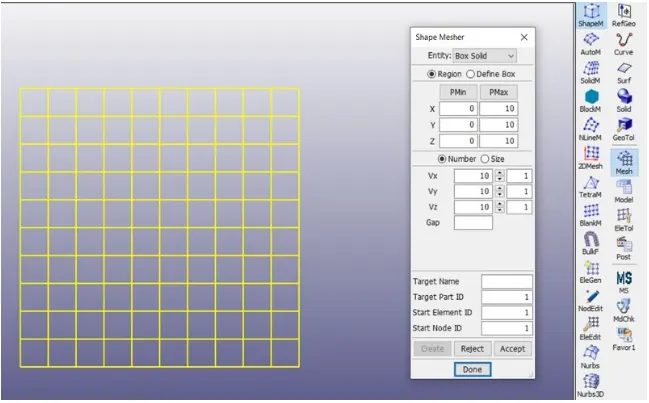
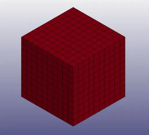
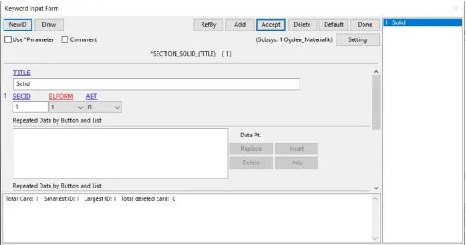
2. Section Card :
Section solid is used and ELForm is set to 1,-1,2,-2 for various simulation.
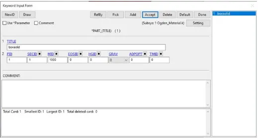
3. Part Card :
Assign the section card and material card to created part.
4. Creating Boundary Condition:
We need to create 3 sets of BC as shown in fig.
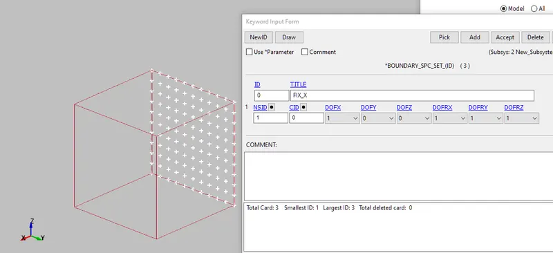
Fig1 Fixed in X direction.
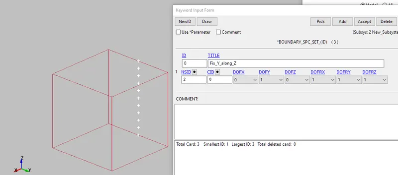
Fig2 Nodes fixed in Y dir along Z direction.
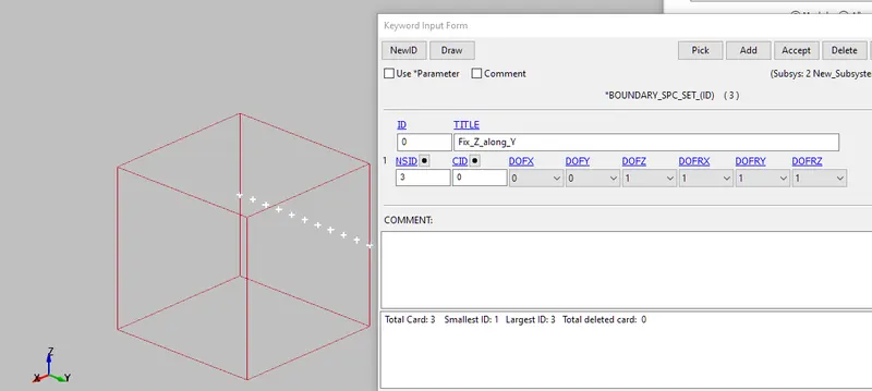
Fig3 Nodes fixed in Z dir along Y direction.
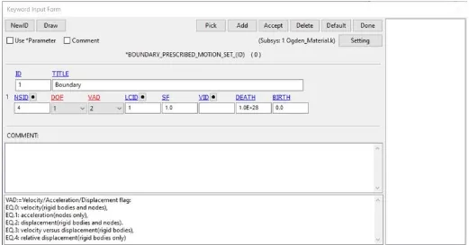
5. Boundary prescribed motion :
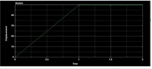
Before setting up BOUNDARY_PRESCRIBED_MOTION_SET the dispalcement has to be calculated .
Stretch ratio = `lamda`=1 + `epsilon_e`
`epsilon_e`= engineering strain = `frac{deltal}{l}`
5=1+`(frac{deltal}{10})`
`deltal=40mm`
6. Control Cards:
Implicit cards are setup as shown below:
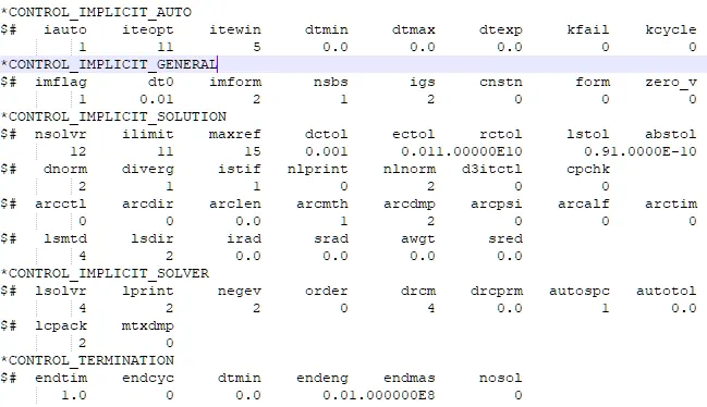
> The CONTROL_IMPLICIT_AUTO adjust the time step fro convergence within the iteopt and itewin values.
> In CONTROL_IMPLICIT_GENERAL imflag is set to 1 to run the simulation in implicit.
> The CONROL_IMPLICIT_SOLUTION is used to specify whether a linear or Non-linear solution is required.
> The CONTROL_IMPLICIT_SOLVER is used to apply implicit calculation , The linear equation solver performs the CPU-intensive stiffness matrix inversion.
> CONTROL_TERMINATION isused to define the end time.
7. Output cards:
Output cards are defined to display the output given by the solver after running the simulation.
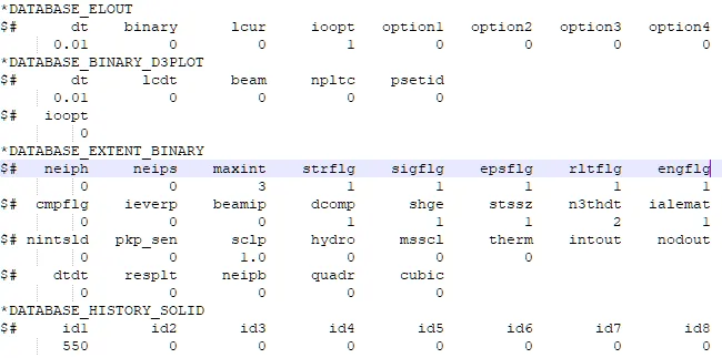
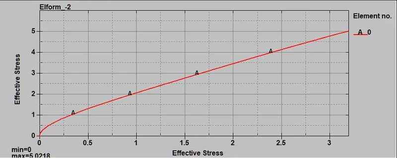
The stress and strains of the elements are saved and stress vs strain plot is derived.
8. Results:
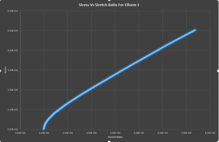
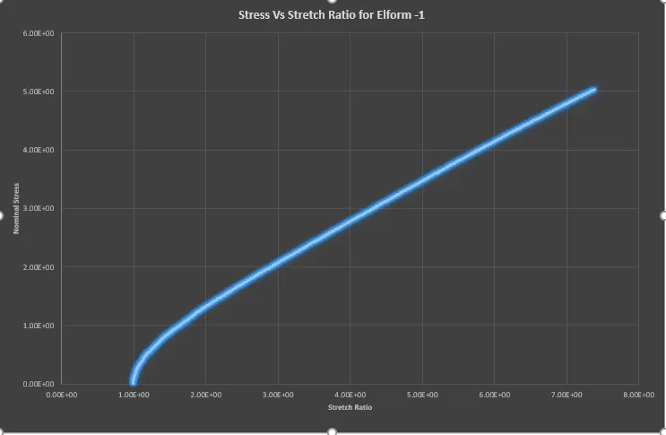
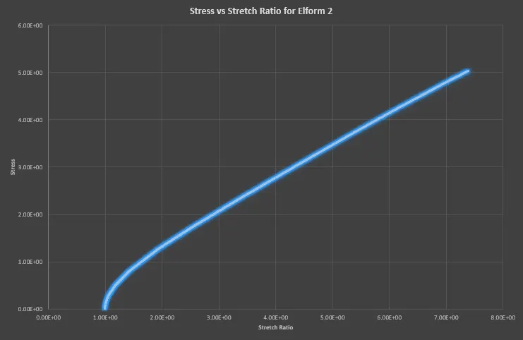
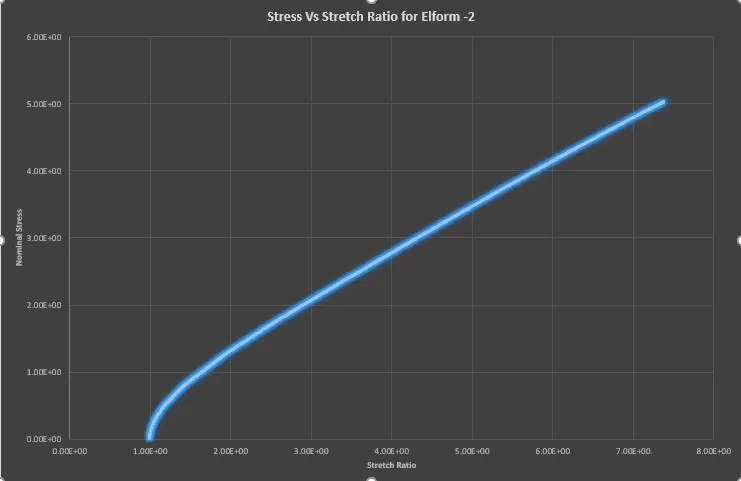
In the run console , it is clear that element formulation affects the itteration steps and computational time ,There is a slight variation in stress value .if we compare he stress data in excel sheet .
Conclusion:
Different element formulation is compared by using tensile behaviour , the results are compared and we get mostly similar curves , the only difference is only slight change in stress, strain values beacuse of shape function which is integrated to get results.