Week - 3 Drop test Challenge
PHONE DROP TEST
AIM: To create a complete simulation file from the given file having just nodes and elements of two parts, a simplified cellphone and a plate mimicking ground to perform a drop test.
Note:
- *INITIAL_VELOCITY card is used to give velocity specifications for the cellphone.
- The height of drop test is assumed to be 1.8m = 1800mm.
- The unit system used is kg, mm, ms.
PROCEDURE:
The given LS-Dyna keyword file is opened in LS-PrePost using option File>Open>LS-Dyna Keyword File as shown in the fig. 1.
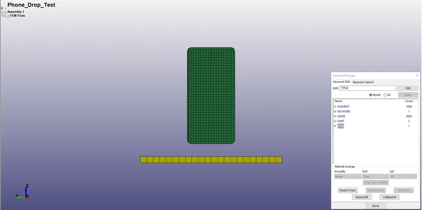
Fig.1. Phone Drop Test LS-Dyna Keyword mesh only File.
The keyword file consists of three FE models i.e, cell phone model, a floor made of shell elements and a floor made of block elements. The parts are named as phone and floor using the option Keyword manager>Parts>Accept. For analysis purpose, the floor made of block elements is deleted using option Keyword manager>Parts>Delete>Done.
1. Part definition:
The part is defined by assigning the section properties and material properties. The section properties of floor is assigned as shell element with 1 mm thickness and ELFORM=2 by using the option Keyword manager>SECTION>SHELL.
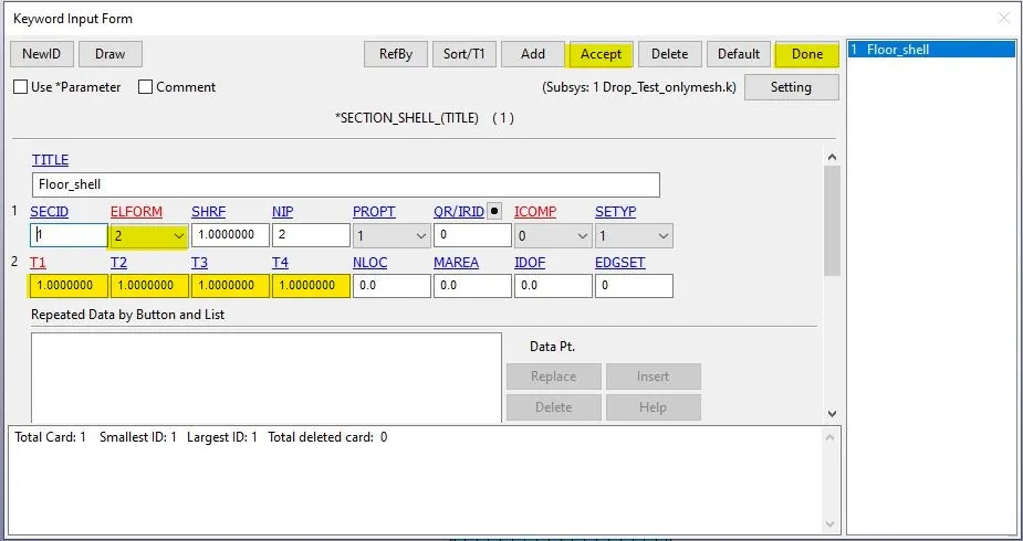
Fig.2.Floor section shell.
The section properties of phone is assigned as solid element with ELFORM=1 by using the option Keyword manager>SECTION>Solid.
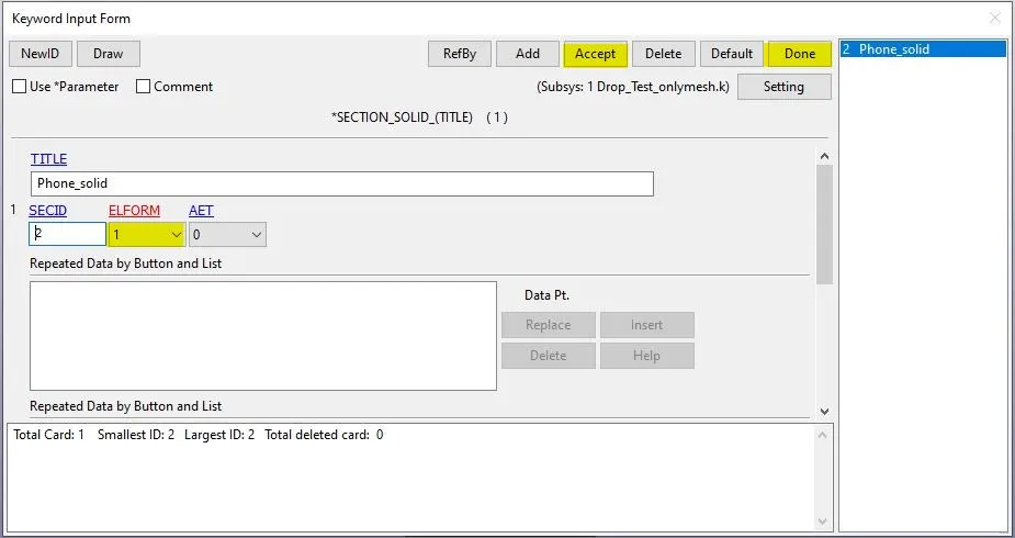
Fig.3. Phone section solid.
The material of floor is assigned as rigid material and the input parameters are shown in fig.4.
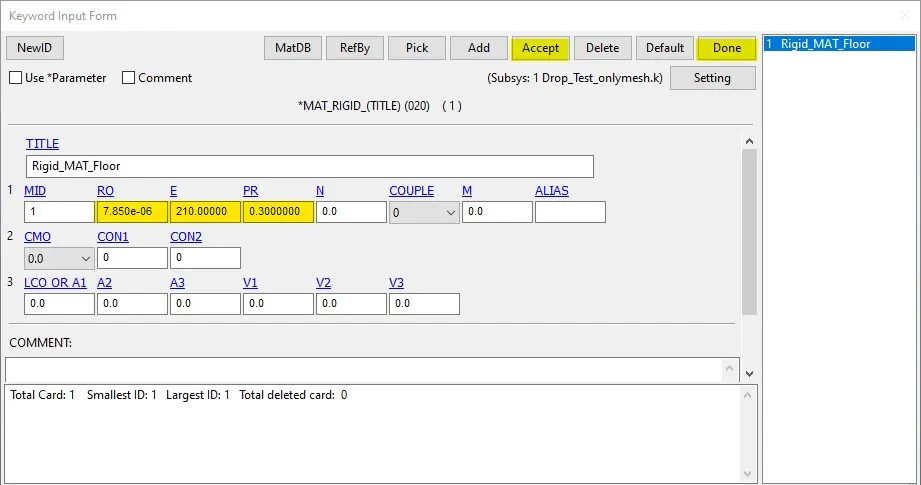
Fig.4. Rigid material.
The material of phone is assigned as Aluminium material and the input parameters are shown in fig.5.
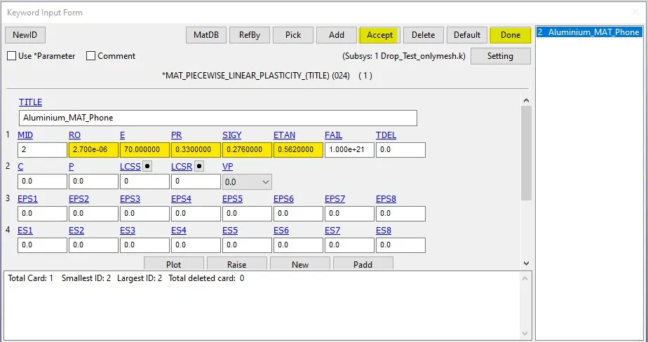
Fig.5. Aluminium material.
The section and material properties of floor and phone are assigned respectively as shown in fig 6 and fig.7.
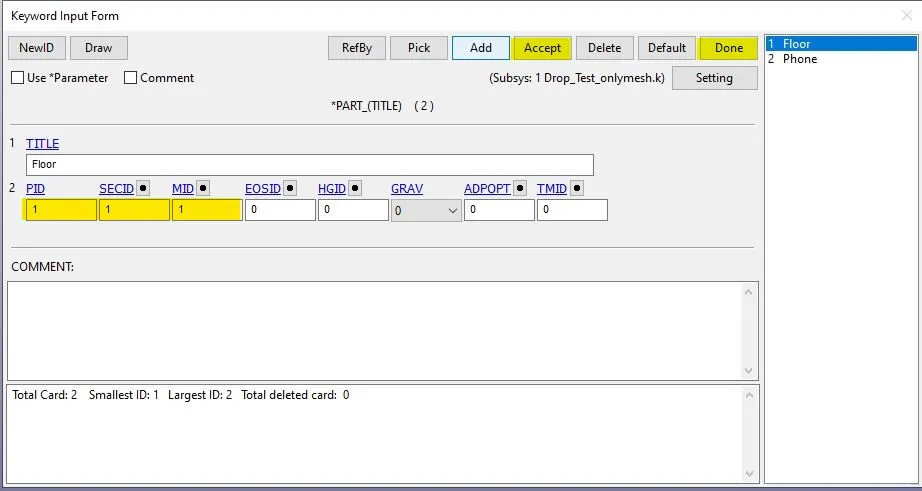
Fig.6. Floor part
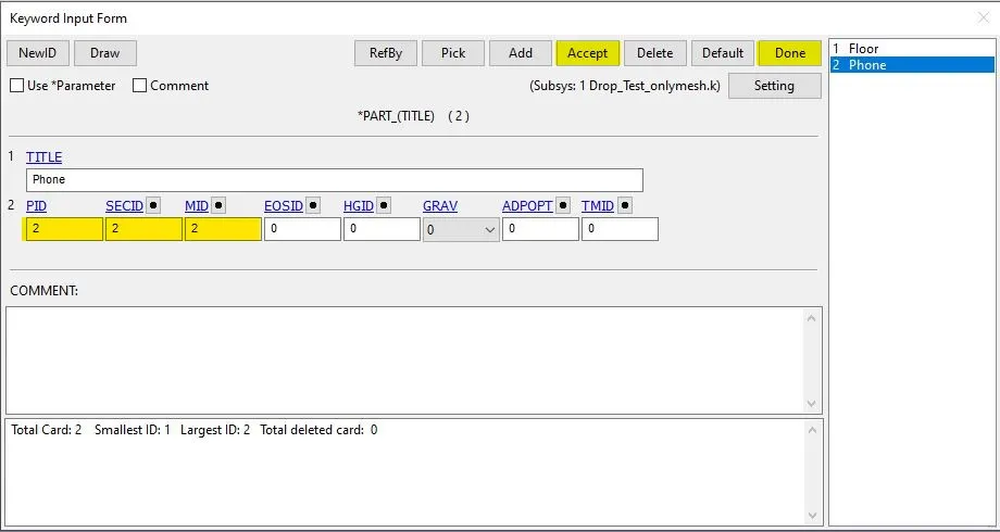
Fig.7. Phone part.
2. Boundary conditions:
The floor is fully constrained along the four edges as a rigid body during the impact is as shown in fig.8.
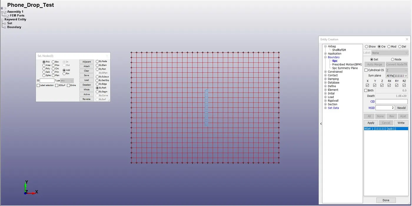
Fig.8. Floor constrained fully along edges.
The top nodes of the phone is constrained along x and y direction and is free to translate along z axis as shown in fig. 9.
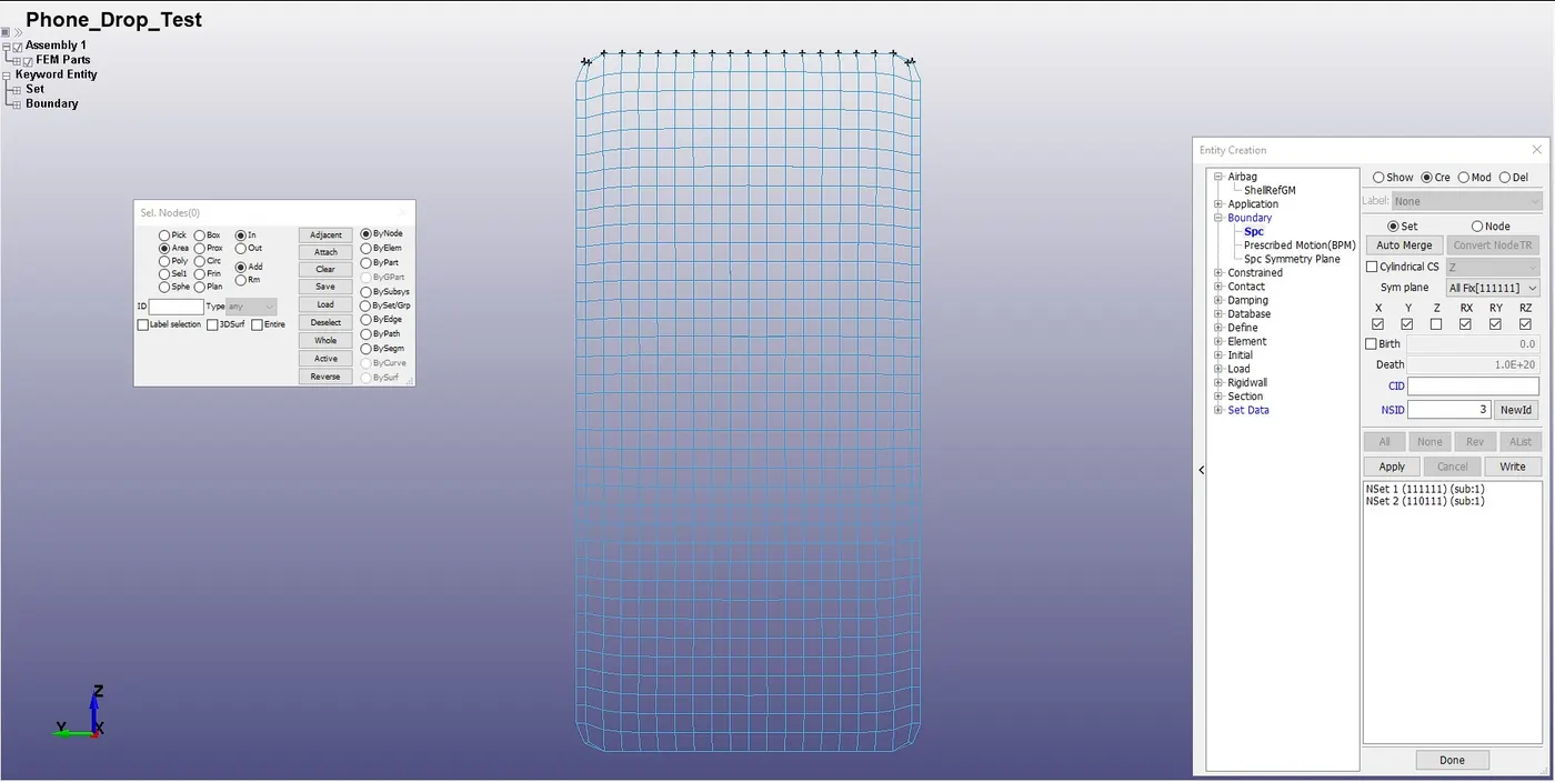
Fig.9. Top nodes of phone constrained along X and Y
The initial velocity is determined using the equation,
`v=sqrt(2gh)=5.94 (mm)/(ms)`
g=accerleration due gravity.
h=height of fall.
Since the distance between the phone and floor is 20.178 mm is very small to make impact simulation. Hence, the phone is assumed to be dropped at a height of 1.8m =1800mm. Therefore, the initial velocity of Vz=5.94 mm/ms is provided along -ve z direction.
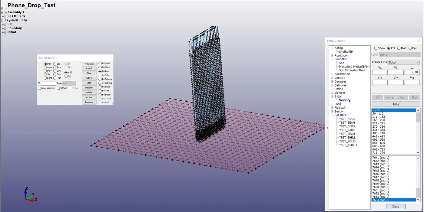
Fig.10. Initial velocity.
3. Contact condition:
The contact type selected is AUTOMATIC_SURFACE_TO_SURFACE. The rigid floor is selected as master and phone is selected as slave.
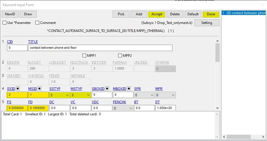
Fig.11.Contact between floor and phone.
4. Control function:
The control energy function is enabled for computing the hourglass energy, stonewall energy and sliding energy.
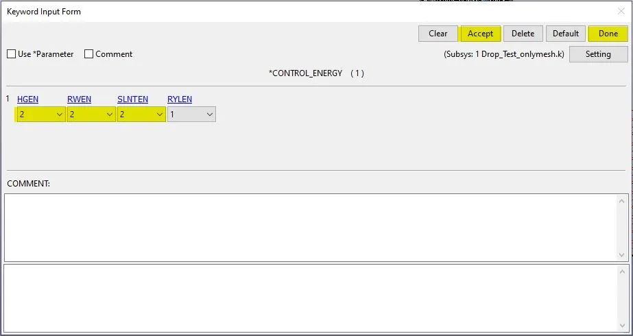
Fig.12. Control energy.
The control termination function is enabled to specify the end time of simulation. The termination time is set for 5 ms to capture the effect of impact of phone on floor.
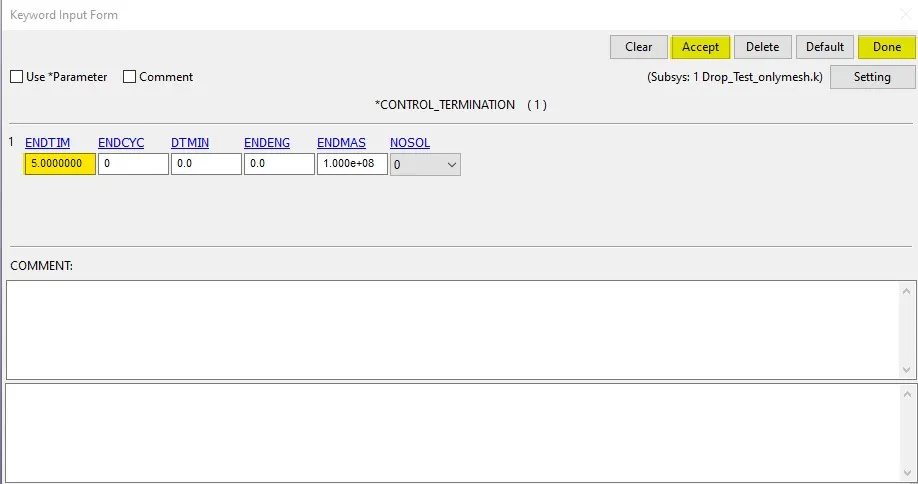
Fig.13. Control termination.
5. Database option:
The time step value of 0.1 ms is given for the BINARY_D3PLOT and in the DATABASE_ASCII option for ELOUT, GLSAT, MATSUM and SLEOUT.
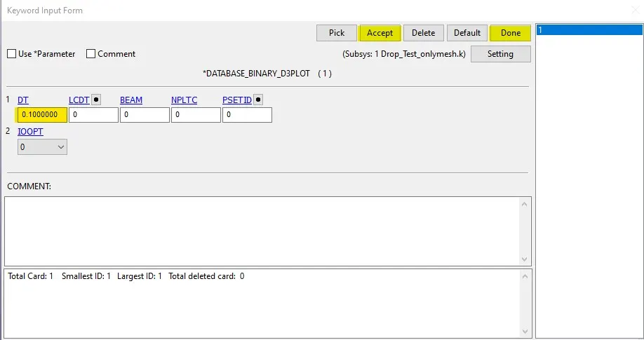
Fig.14. Database binary_D3plot
The keyword file created is checked for errors using the option keyword manager>model check. The keyword file is saved using ‘.k’ extension and is made to run in the solver by getting normal termination message as shown in fig. 15.
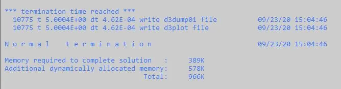
Fig.15. Normal termination.
6. Results:
The D3plot output file is opened in LS-PrePost using option File>open>LS-Dyna binary plot.
The Von-Mises stress during the time of impact is as shown in fig. 16.
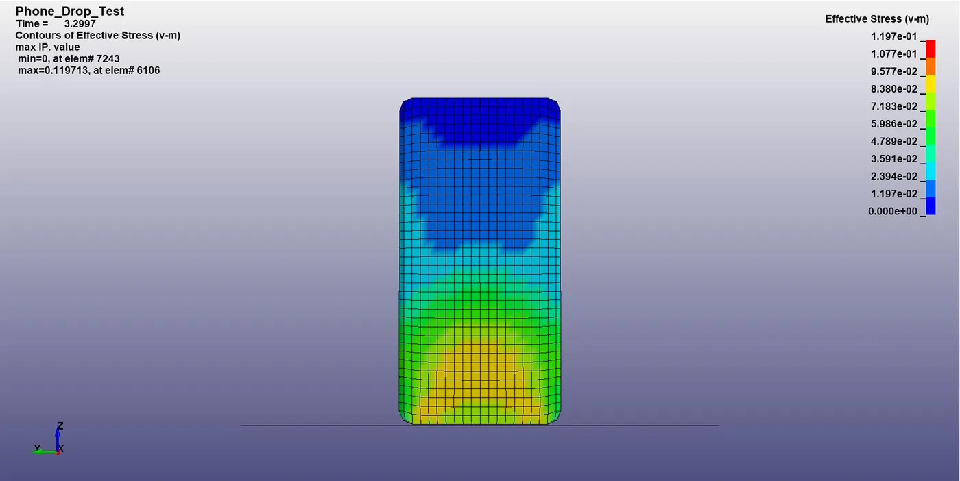
Fig.16. Von-Mises stress during impact.
The maximum Von-Mises stress developed in the phone is as shown in fig. 17.
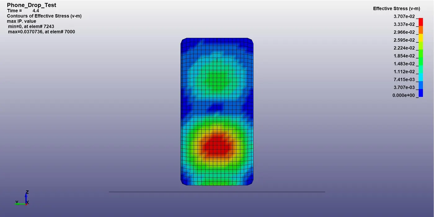
Fig.17. Maximum Von-Mises stress.
The graph of kinetic energy vs internal energy vs total energy shows the abrupt changes during the time of impact of the phone with the floor is as shown in the fig. 18.
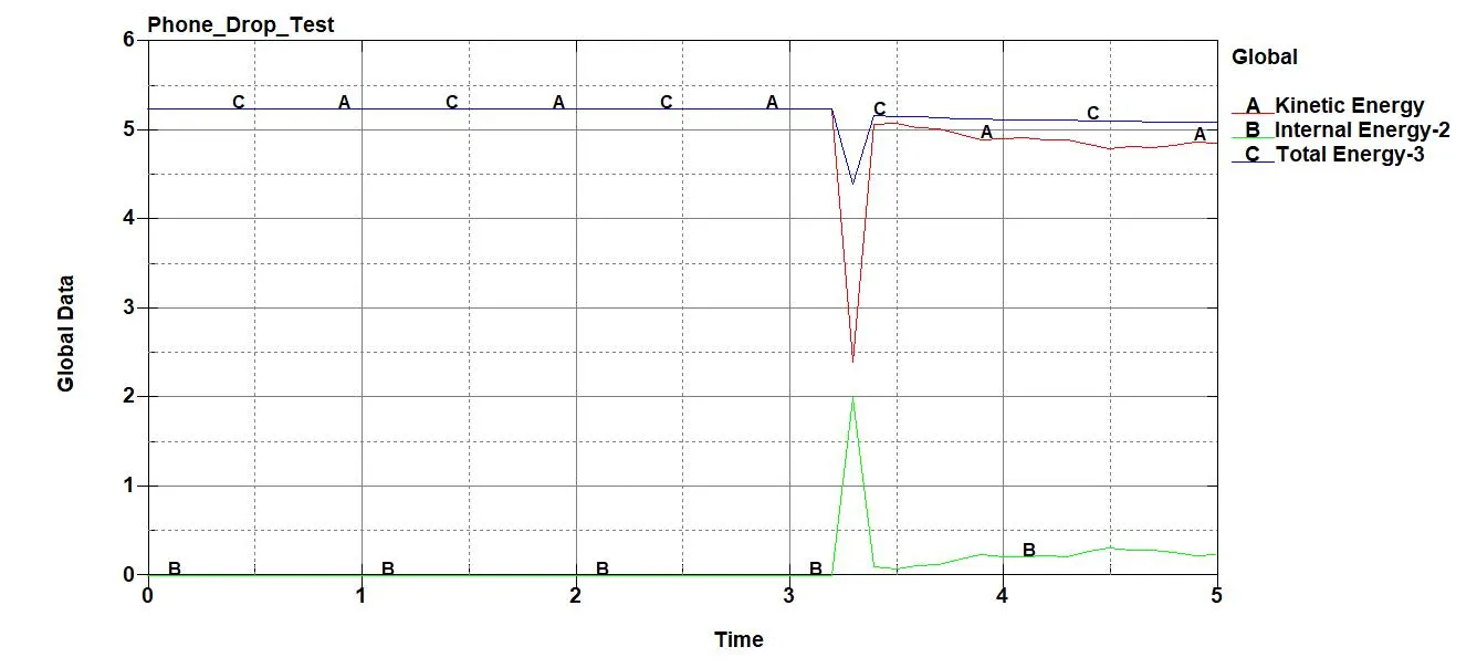
Fig.18. Kinetic Energy vs Internal Energy vs Total Energy plot.
The Von-Mises stress contour animation is shown below.
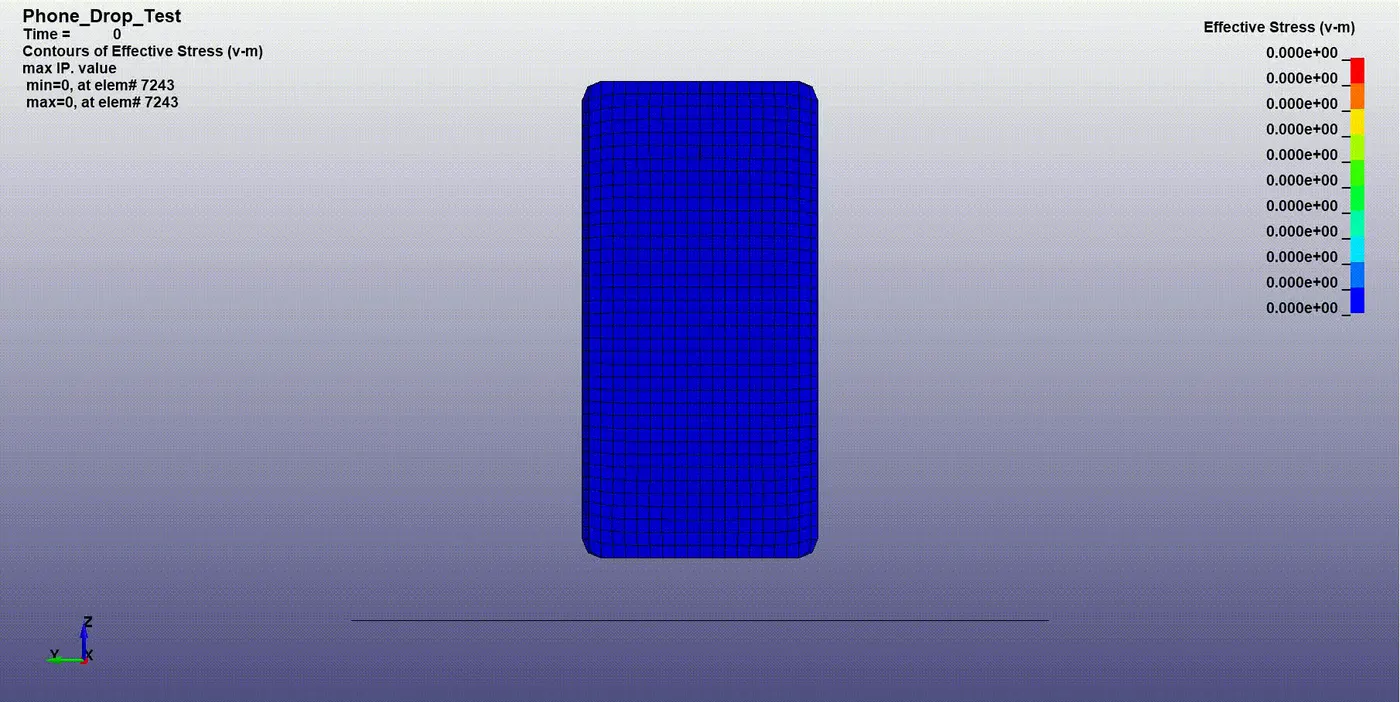
CONCLUSION:
- The keywords necessary to build the drop test was created from scratch.
- The model was solved successfully and the results are analysed.
- Learned to build a solver deck in LS-Dyna and extract the outputs to interpret the results.
Google Drive Link: https://drive.google.com/file/d/11yb7qa58YFCZR5Qz1NR8PtXDEm4KiZrY/view?usp=sharing