Week - 3 Drop test Challenge
AIM; To perform a Drop test Simulation of a mobile phone on the rigid floor body with suitable keyword Parameters and plot the results from it.
PROCEDURE;
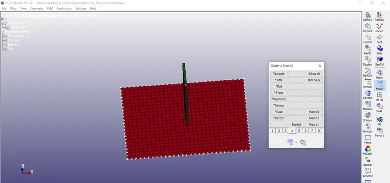
- Import the given Drop_test_onlymesh.k File in to ls dyna GUI.
- The File Only Consists of the nodes and elements of the Mobile phone and the floor shell plate.
- To perform the Simulation, materials, Section, initial velocity, Contact Interface, Boundary conditions, and ther output following Must be Specified.
- Give the material properties for the parts given.
- Create the section for shells and solid property to the parts in the model.
- Then after we need to give boundary conditions to the model.
- Then we need to give the Data base for Binary D3plot and ASCII output results.
- We need to request the output results from the solver.
- Analyse the result from the solver.
GIVEN MODEL;
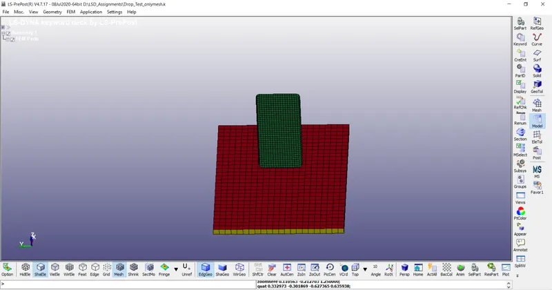
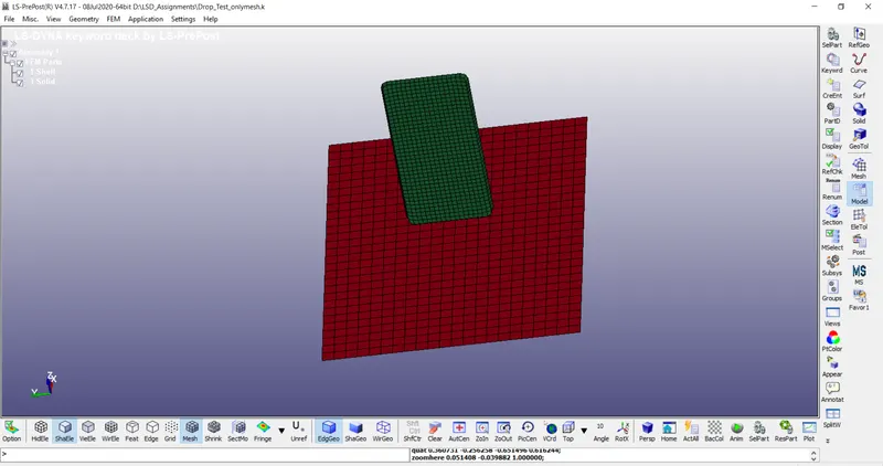
The model contains three parts.
Among them we need to delete the extra solid body.
CREATING MATERIALS;
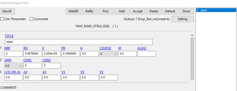
- For creating the materials go to Model and Part>Keyword Manager > All> MAT > Select the Material card and define the material properties like mass density, Young's modulus, Poisson's ration, Yield point stress values for both the material cards.
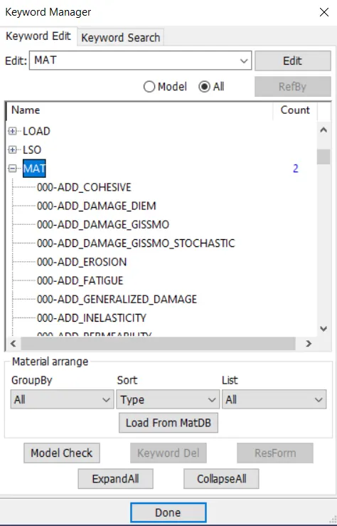
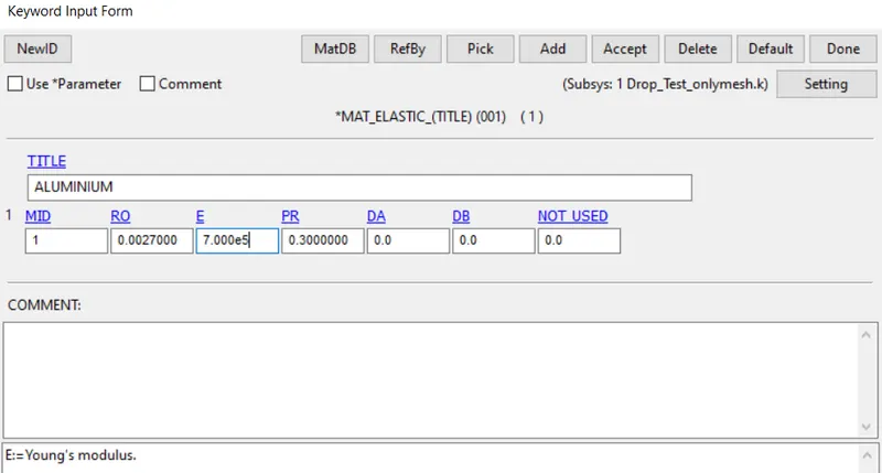
- For this model assembly we use two material properties.
- The linear elastic material to the phone with an aluminium material and rigid material to ground floor with a steel property.
BOUNDARY CONDITIONS;
SPC
- go to Model and part deck >create entity>Bcs>spc.
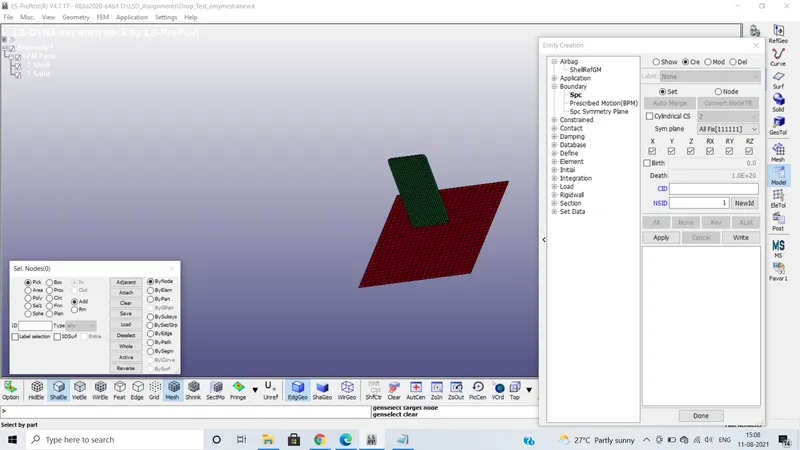
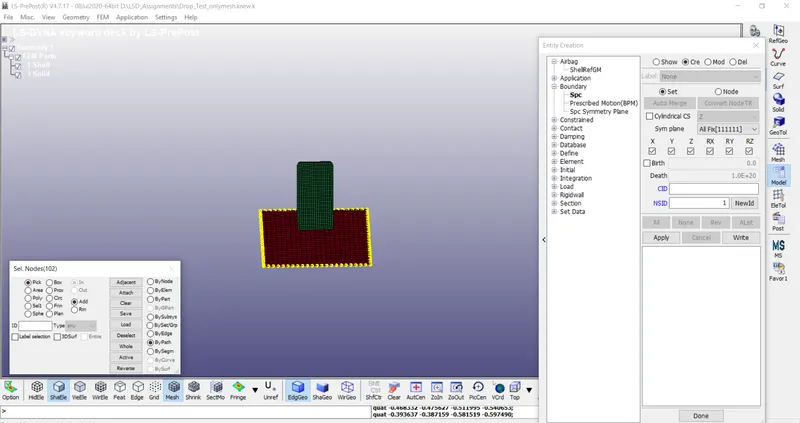
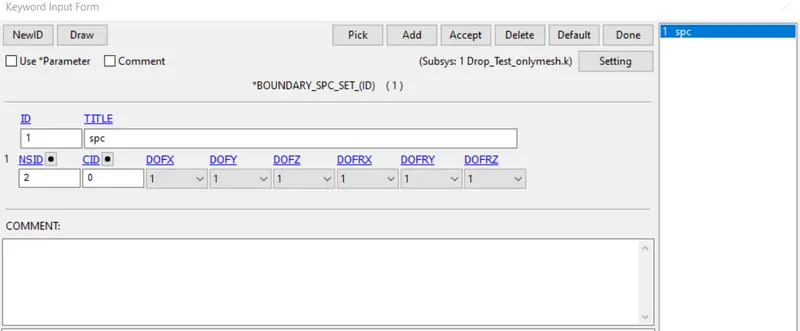
- select the create ,where we have to pick the nodes of the bottom rigid body and constrained the xyz and rx ry rz axis of the body.
- Mention the node set id(NSID) and apply it.
INITIAL VELOCITY;
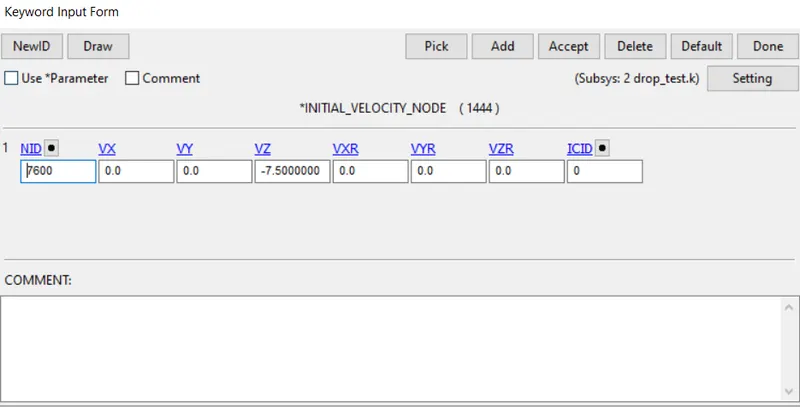
- go to Model and part deck >create entity>Initial>velocity.
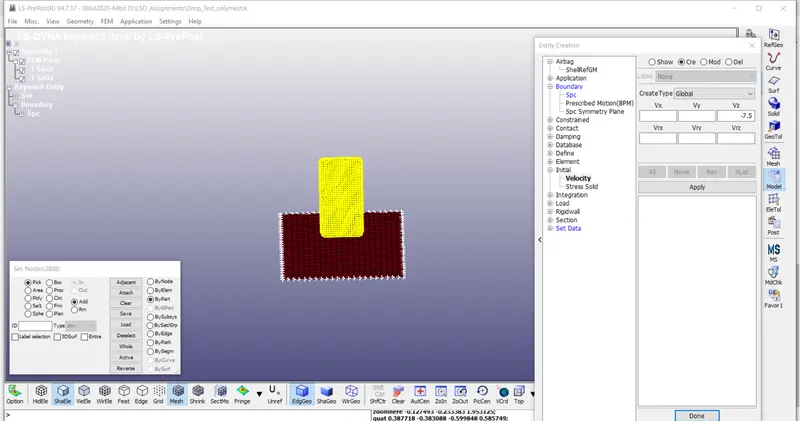
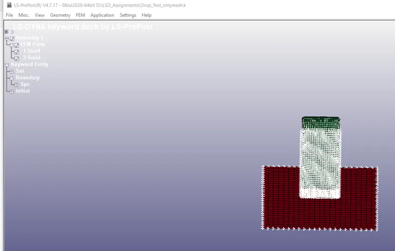
The velocity of 7.5mm/ms is given to the mobile phone. As the phone is dropping along a negative z-direction so assign the value in the Vz(direction)= -7.5 mm/ms is given as initial velocity.
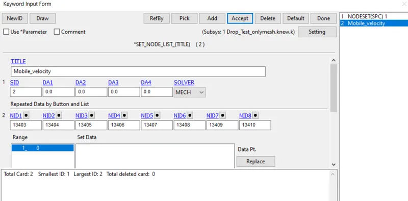
NODE LIST;
SECTION;
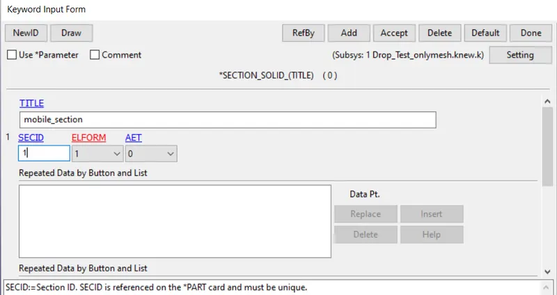
Section is used to create the proprtites of elements,element formulations and thickness of the particular model.
model > Keyword manager > section > solid.
Shell section:
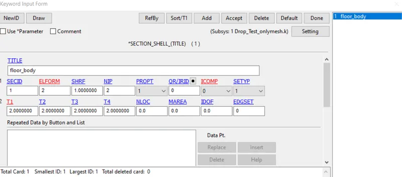
- same as solid use used to create the section for shell elements are,
- model > Keyword manager > section > shell.
- specify the sectionid(SECID), element formulation and thickness.
PART;
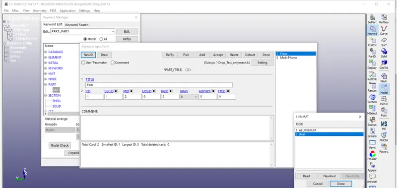
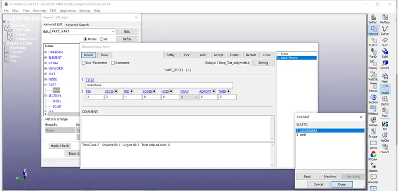
To define a part we must have nodes, elements, sections and materials.
CONTACT;
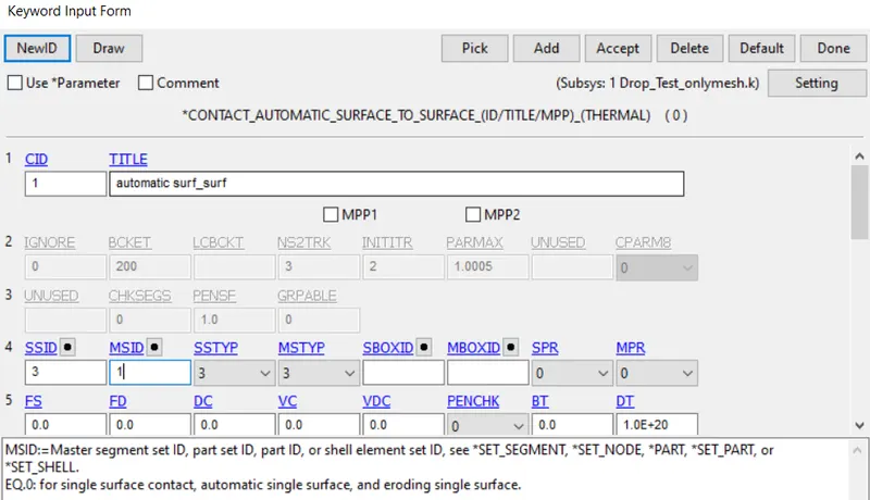
- Automatic surface to surface
- The surface-to-surface contact interface is used for the simulation. The command used for creating the contact interface between them.
- Select the slave as phone and master as floor shell part .
- The more stiffer part is consider as master.
CONTROL;
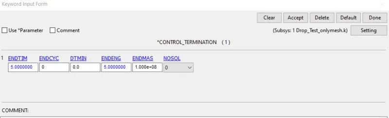
- Control cards is used to set the Termination time for an simulation model.
- To set control card,Model >Keyword manager > control >Termination command is used. The simulation time is set to 5.00ms.
DATABASE;
Used for creating the output results for the model.
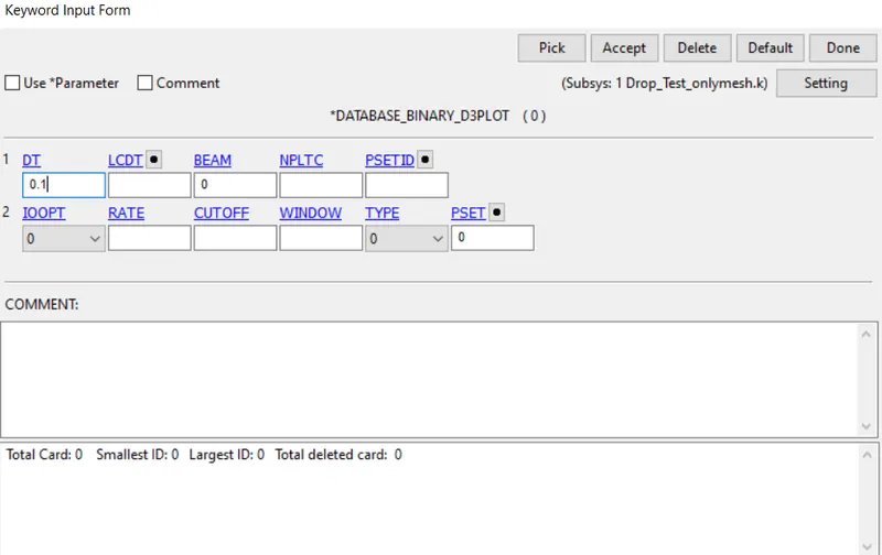
BinaryD3plot
Keyword Manager > Database >Binary D3plot >DT 0.1. It prints the Output file at each 0.1ms. The D3PLOT card gives animation view get the results in the post-processing data after the simulation.
ASCII
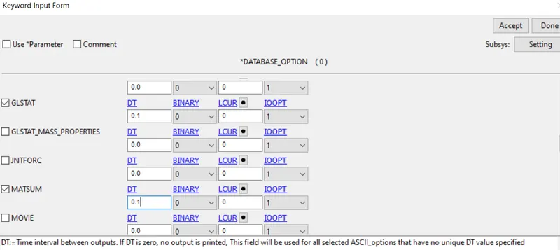
Go to Keyword Manager > Database >ASCII >GLSTAT and MATSUM.
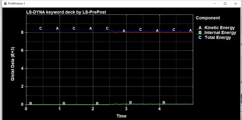
GLSTAT which gives global energy data like Kinetic Energy, Internal Energy and other types of energy.
MODEL CHECKER;
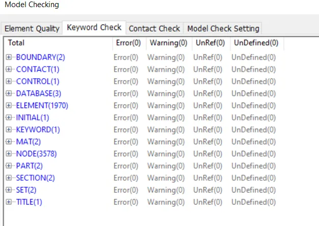
Before Run the Model , we have to check the model to avoid Errors and Warnings in the part.
For model checker go to HELP Tab>click on Old to New and select the Model checker.
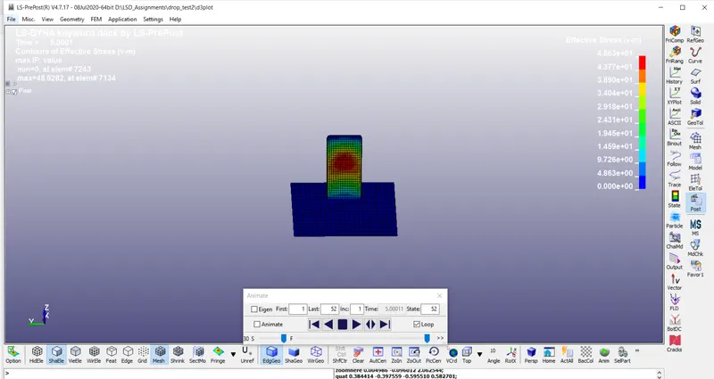
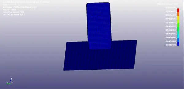
The von moises stress is created at 48N/M^2.
GLSTAT PLOT;
- In this plot we have plotted the Kinetic energy,Internal energy and Total energy.
- From the plot we can see that, when mobile impcat to the ground, we can see deflection in Both Kinetic energy and Internal energy.
- The Kinetic energy is started at the 2.5ms and slowly becomes reduced due to the internal energy produced by the floor ground . The Total energy is remaining constant throughout the process.
https://drive.google.com/file/d/1UyOYT_0-8q8Rn9GscbPCB2DrTsbF14wX/view?usp=sharing