Week - 3 Drop test Challenge
Objective:
Creating the LS-DYNA simulation for the drop test.
1. In this problem, mobile is dropped on a rigid base. The colliding distance is very close and mobile hits the surface with an initial velocity
2. The analysis is done from the instant mobile hits the colliding surface and few milliseconds after that
(Orientation of phone hitting is ignored)
Models in File:
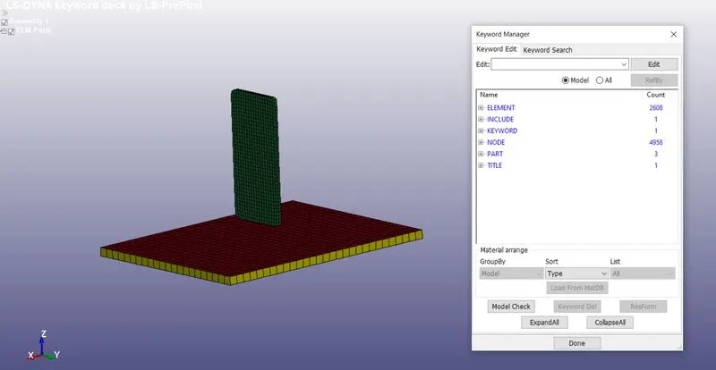
* The file contains 3 part files - 2 solid and 1 shell
* The phone body (Shown in green) is defined as one solid part and the floor (shown in yellow) is also defined as a solid part
* Furthermore, another floor file is provided (shown in red) as a shell part
PRE-REQUISITES:
1. Importing .k file into LS-PRE POST
2. Creating the procedure of the experiment
3. Creating keywords for analysis
4. Saving the .k file for solving
5. Interpreting plots
PROCEDURE OF EXPERIMENT:
1. The colliding surface is ground and can be considered rigid and constrained in linear x,y,z and rotational x.y,z
2. The colliding surface is the master contact set segment and the cell phone is the slave set segment
3. The mobile contact needs to be defined with the colliding surface
4. The initial velocity and direction of motion of mobile are to be defined
5. Computation time for solving solids is more compared to shell elements
6. Computation for reaction forces on the rigid wall is not required on collision, hence we will rigidise the collision surface and not by defining SPC boundary
SYSTEM OF UNITS:
Kg, mm, s
KEYWORDS USED:
*CONTROL
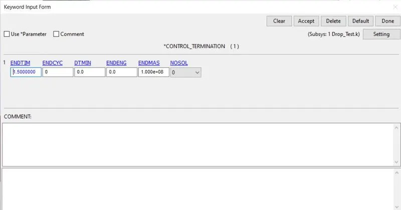
To enter the entire duration of the simulation to run. i.e Termination time.
*DATABASE
1. Binary files, ASCII files
2. Time steps for the event to happen
*PART
PartID, SectionID and Material ID for the mobile and colliding surface.
*MAT
1. Elastic-plastic card for a cellphone with aluminium properties.
2. Rigid material properties for the wall.
*SECTION
Section ID for solid elements.
Section ID for shell elements.
*INITIAL_VELOCITY
To assign the velocity to the selected nodes of a cell phone.
*CONTACT
To establish contact between the Cell phone and colliding surface.
*SET
1. To establish contact between two parts we need to define node segments for cell phone as well as rigid collision surface.
2. Node set for velocity assignment.
PROCEDURE:
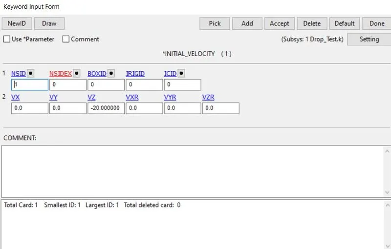
1. Assigning initial velocity to the cell phone:
- Go to create an entity
- Go to Set Data
- Go to *Set_Node>>Create>>SetID as 1>>Select nodes of cell phone by area>>Apply
So by this way, we can create a Set for nodes, later we can assign velocity to this setid:
- Choose the NSID as 1
- Enter VZ as -20mm/s (This is velocity of 20mm/s in negative z-direction)
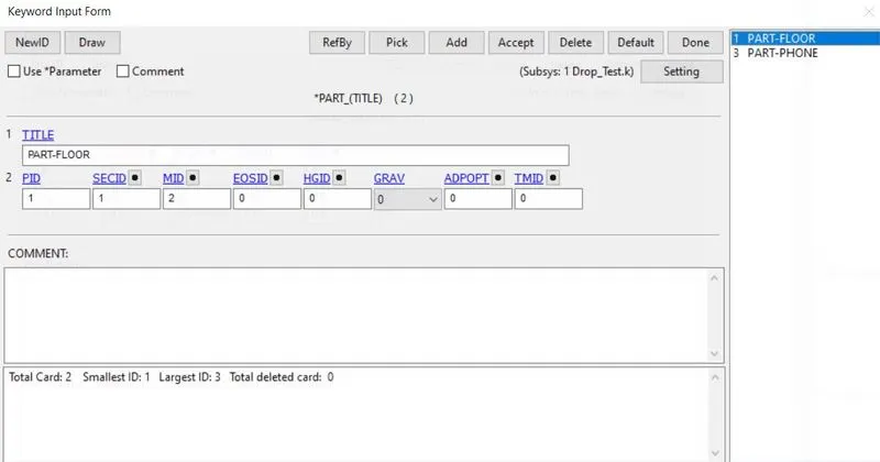
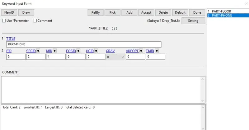
2. Assigning part ID:
Rename the PartID as:
1. PART-FLOOR
2. PART-PHONE
3. Assigning Section ID:
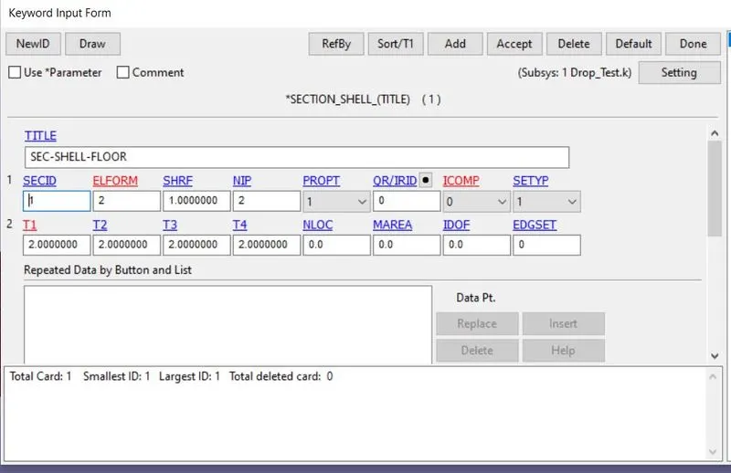
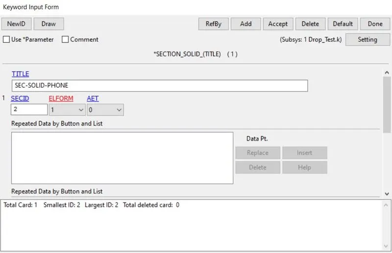
Creating sections for collision surface and cell phone. Choose the appropriate element formulation (ELFORM):
1. Shell section for collision surface as it comprises of shell elements: ELFORM = 2, Thickness = 10mm
2. Solid section for cell phone as it comprises of solid elements: ELFORM = 1
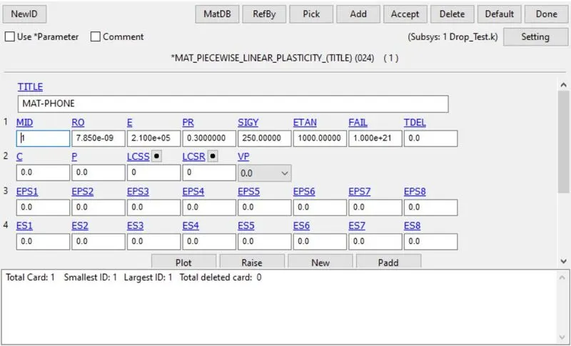
4. Assigning Material ID:
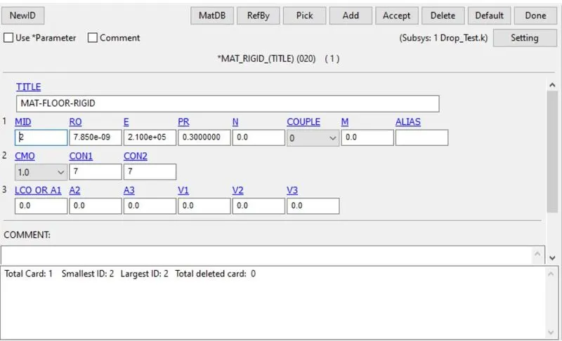
Now, as per our analysis, 020_Material_rigid is chosen as the material for collision surface:
MID = 1
Title: Collision surface.
E= 2.100e+05
RO= 7.850e-09
PR= 0.3
Defining constraints for rigid material:
CMO = +1 constraints NSID in global x,y, and z coordinates.
CON1 = 7 to constraint translational x,y and z.
CON2 = 7 to constrain rotational x,y, and z
5. Assigning CONTACT between Cell phone and Collision surface:
As there will be contact between cell phone and collision surface so we need to define contact:
Contact can be defined only for node segments
We need to define two node segments, one for:
1. Cell phone node segment
2. Collision surface node segment
Go to create an entity
Go to Set Data
Go to *Set_Node>>Create>>Enter SetID>>Choose nodes by area>>Title(optional)>>Apply
Setting up Contact Keyword:
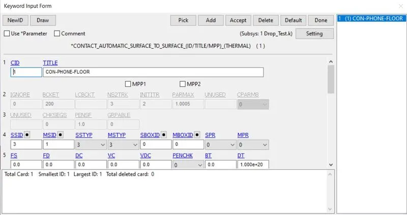
*Contact keyword >> Automatic surface to surface
Enter SSID as node segment for Cellphone
Enter MSID as node segment for Collision surface
6. Assigning CONTROL Keyword:
7. DATABASE Keyword:
D3plot file (Binary)
GLSTAT, SLEOUT, SPCFORC, RCFORC and MATSUM (ASCII)
DT = 0.1 second
PLOTS:
KE, IE, TE Vs Time
We can see the significant changes in Kinetic Energy, Internal Energy and Total Energy
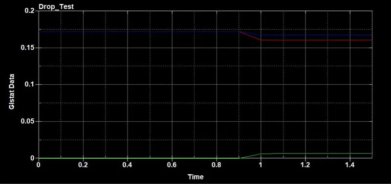
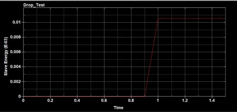
SE vs Time
We can see the Slave Energy increases with respect to time