Week 3 Challenge : CFD meshing on Turbocharger
Aim: For the given model, check for the geometrical errors to make appropriate volumes. Create and assign PIDs as shown in the video. Perform surface mesh with the given target lengths as per PIDs.
Blade stage-1 = 1 mm
Blade stage-2 = 1 mm
Impeller = 2 mm
Shaft rotor = 1 mm
Turbo casing = 5 mm
Compressor casing = 5 mm
Inlet casing cover = 5 mm
Also perform Volumetric mesh for the required volumes.
Setup:
- Import the geometry
- Check and clear the geometrical error
- Generate surface meshing
- Generate volume meshing
Procedure:
Import the geometry in ANSA.
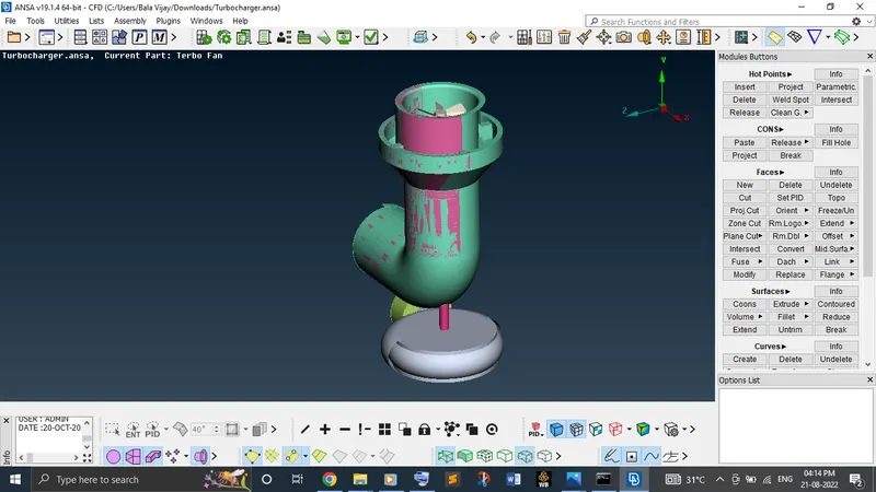
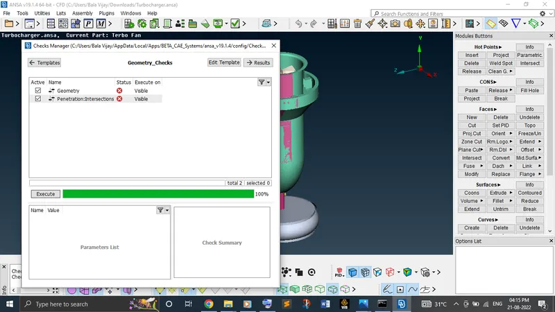
Check the geometrical and interceptional errors by using check manager.
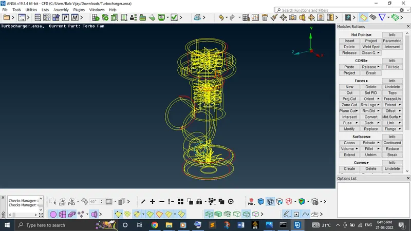
Clear each and every single cons first and then triple cons. If triple cons are necessary at a particular location where three faces joining at a common con, just ignore it.
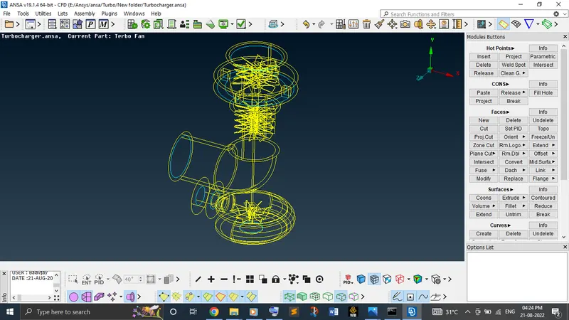
While clearing single cons at a complicated location like a curvy outer cover is missing, it's difficult to create a surface just by using coons or fitted option in topo module. In order to create a surface like that location, create more hot points using parameters option under corns.
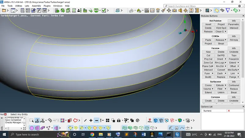
If geometry is having so many PIDs, need to make sure any PIDs are overlapping together. If so, just delete the unwanted surface.
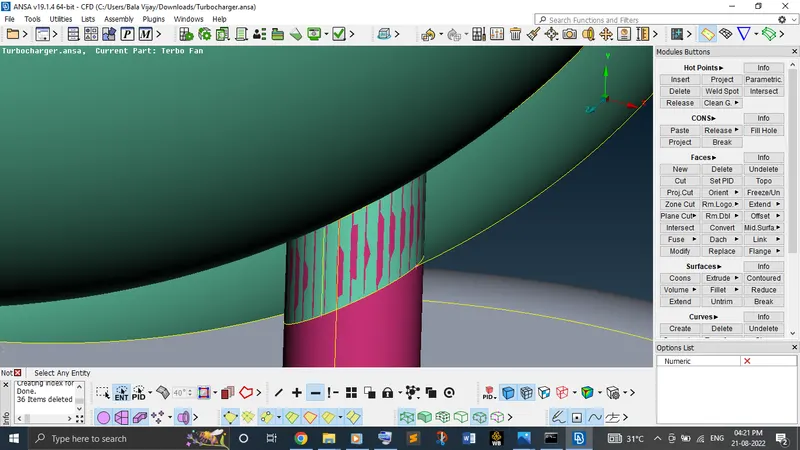
While trying to delete the unwanted surface, facing any difficulty just project the cons on the surface which you need to delete if there is no particular surface and then delete the surface.
Now, start the surface meshing. As per given target length, first set the perimeters and macros length for an individual PID and then set the target length in mesh parameters. Also set the maximum and minimum length as well in mesh parameters & quality criteria.
Repeat the same procedure for each individual PIDs to set the target length.
To generate mesh, use spot mesh option and just drag the PIDs and click scroll button to complete the process.
In case, where two different target length having surface sharing a same cons, one PID face might end up with fading mesh. Need to make sure of this conditions and clear it. To overcome this, just don't change the macros length for any one of the PID. To isolate those surface, just cut randomly on the surface which made changes in its surface mesh. Once completed all these, before go to the next step, need to make sure if the geometry has any unmeshed surface which is shown in the GUI itself.
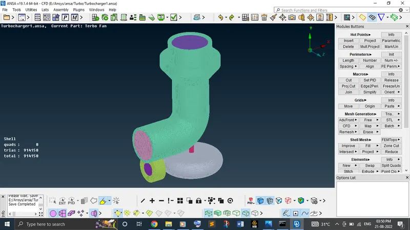
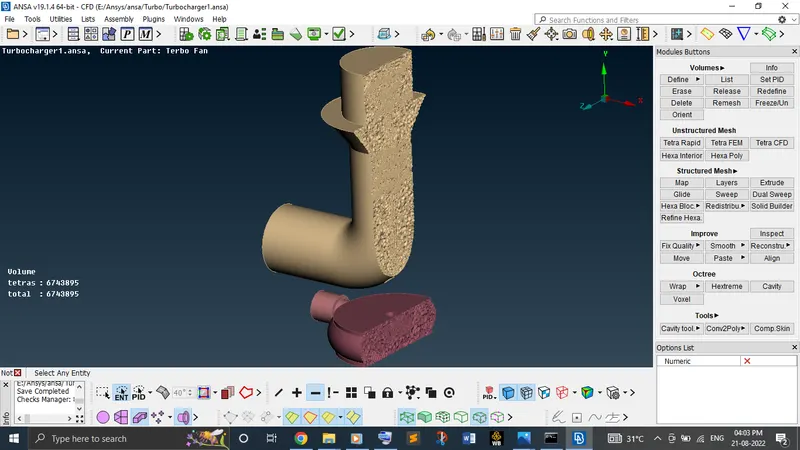
Finally, start the volume meshing. Volume meshing is nothing but a process of converting 2D surface mesh to 3D solid mesh.
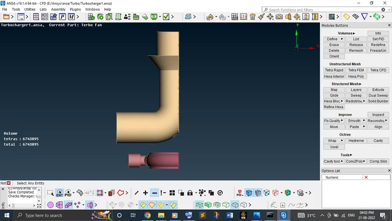
In the volume mesh, go to the define and check the whole database whether the geometry has any flaw like leaking in auto detection mode. If geometry has any thickness portion, auto detection will shows it which is not required for the volume mesh because no flow has going to take part of it. So, delete those volumes and keep the necessary volumes. Remesh those remaining volumes with tetra CFD mode. Now all the kept surface has converted into 3D volume mesh.
Learning outcomes:
By this challenge, learnt a bit more options in topo and mesh module like at complicated locations how to clear the single cons, how to project the cons, how to delete the surfaces using global delete option, how to create surface at a vacant by creating new hot points and how to check and clear the penetration interferences. Also, newly learnt about volume mesh module like how to check whole database of the volume and how to clear those auto detections to create volume mesh finely.
Conclusion:
From the result obtained, we can conclude that when we provide the target length for each and every PID individually, we are getting better mesh quality. Also, we can witness the volume mesh variation in the location of the blades and shaft due to the different target length between compressor casing and blades. The geometry seems finer and smoother which is helpful to get good CFD result.
Geometry file drive link:
https://drive.google.com/file/d/1ybpBZdhibHTsvml333y-WT41D_kZglmB/view?usp=sharing