CFD meshing on Turbocharger
AIM:
This project aims to mesh a turbo charger for conducting CFD analysis.
OBJECTIVE:
The main objective of the given challenge is to perform surface mesh and volume mesh on turbo charger and also geometry clean up with the surface mesh for the PID's as
Blade stage-1 = 1 mm
Blade stage-2 = 1 mm
Impeller = 2 mm
Shaft rotor = 1 mm
Turbo casing = 5 mm
Compressor casing = 5 mm
Inlet casing cover = 5 mm
PROCEDURE:
Geometry clean up:
The geometry is imported into ANSA. The .ansa file can be found here.
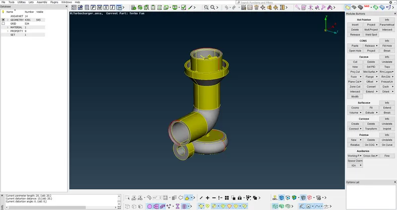
as we can see the geometry has errors. we need to clean up the exterior and interior errors. We start with assigning PID colors to the components using the product manager in the top menu.
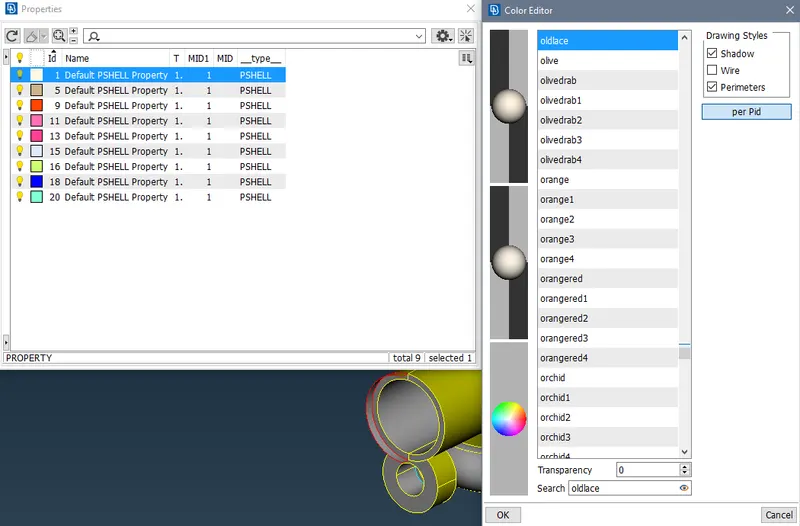
We select the color and click on Per PID to assign the respective colors to the components. We repeat the same procedure for all the components
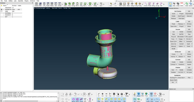
We can see the purple glitching on the green surface. This means that there are 2 surfaces overlapped on each other at that location we use the PID selection to select that and delete. We use the basic methods like create faces to eliminate all the single cons.
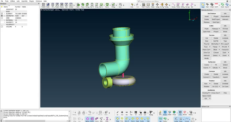
For creating the volumetric mesh. We need to seal the region where the fluids flow, Hence we close all the inlets and outlets.
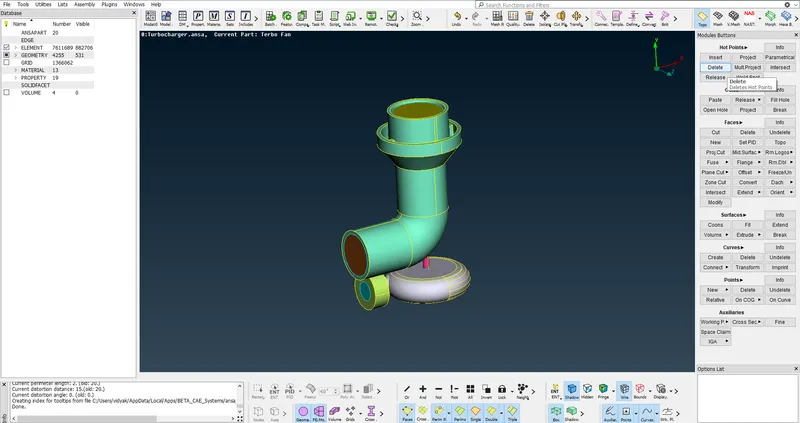
To mesh we should ensure that there are no single cons. Single cons indicate an opening. Once we seal all the openings the wireframe mode of the geometry will look like this.
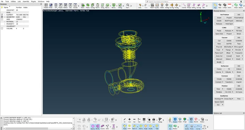
The blue circles indicate triple cons. These cons are not errors and are required to make the geometry water tight.
Before going into meshing we just check the geometry for any errors apart from triple cons. This can be done using the ANSA check manager in the top toolbar.
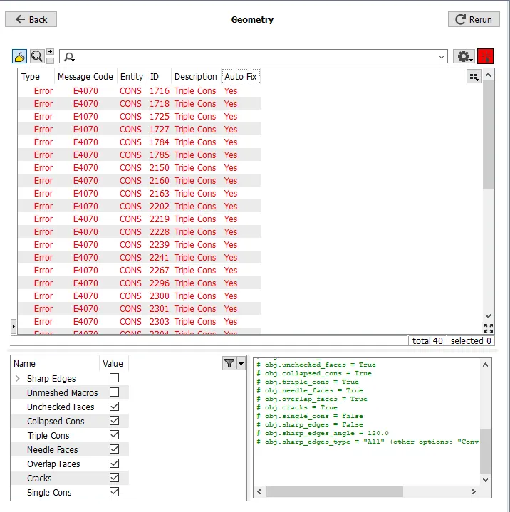
The errors we get are the triple cons at the sealed off locations this indicate that we can proceed with meshing.
Assinging relevant PID's:
Click on Surfaces > Set PID > click on surface that you want to assign a PID and also make sure that wire option is enabled
Left click on surface to select it and click middle mouse button to assign a new PID to your selected surface
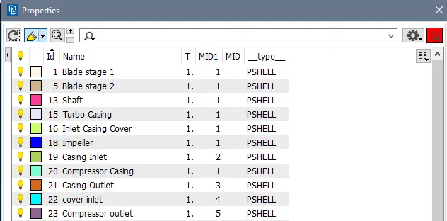
Repeat the same process to assign PID's for remaining surfaces
Surface Meshing:
Select the MESH module button > parameters > length
Drag the cursor to cover the entire model and click middle mouse butto to give the mesh size as 5mm for entire model
Select Mesh generators > Free mesh and drag the cursor to cover the entire model and click middle mouse button
The entire model is meshed with size of 5mm
Similarly Meshing of individual components is done according to th given requirements
Blade stage1 = 1mm
Blade stage2 = 1mm
Impeller = 2mm
Turbocasing = 5mm
Compressor casing = 5mm
Shaft = 1mm
Use the same procedure as of 5mm and apply to individual parts
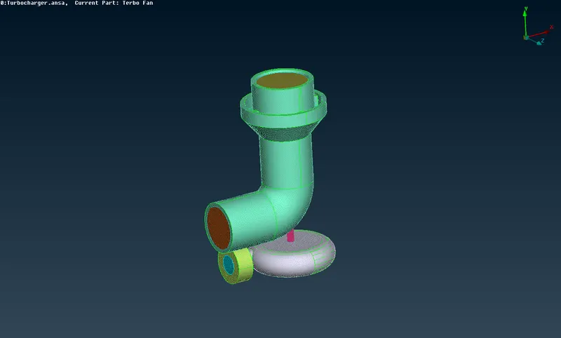
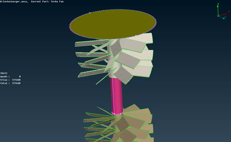
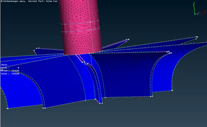
We can see that at the place where the shaft meets the components having different target length. The mesh adapts such that there is a connectivity between the two components.
We can see that the mesh has total 882706 components. All triangles and no quads. This means that we have meshed our geometry correctly.
Volume mesh
For generating a volumetric mesh we go to the right side menu and in the volume tab > Define > use the entire database and press ok.
It should detect a total of 8 volumes. In those 8 volumes we need only 4 volumes. These volumes are the thickness of all the components.
It should be as shown
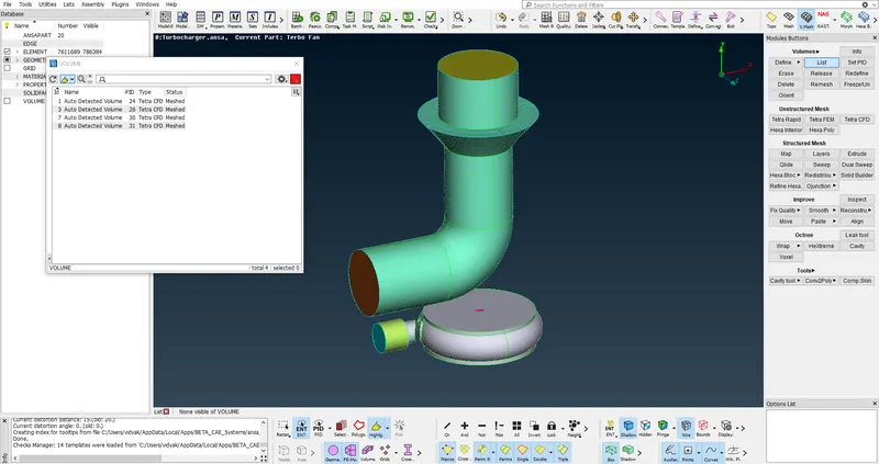
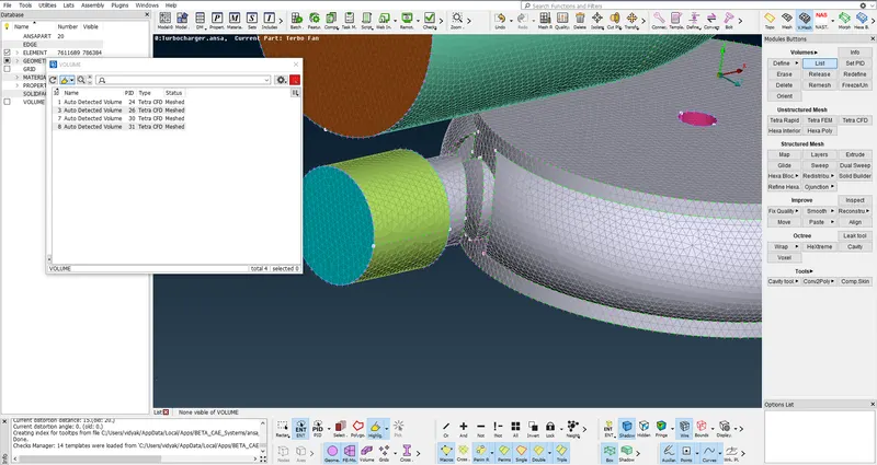
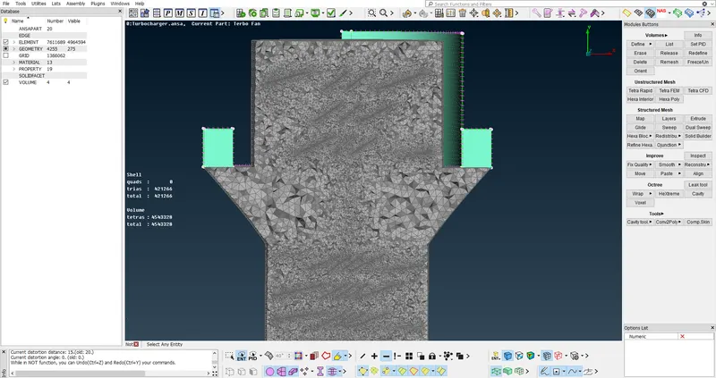
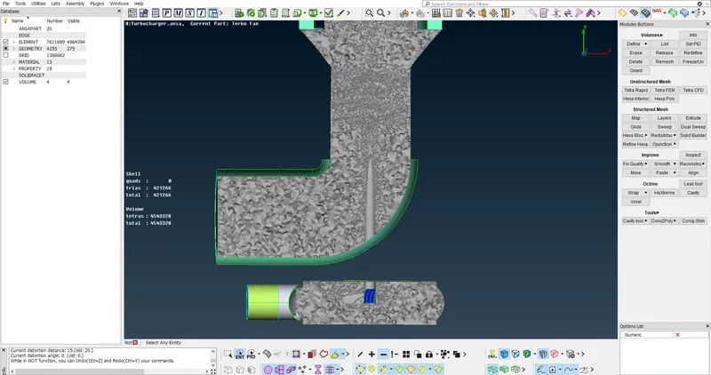
Once the required volumes are extracted we right click on these volumes select remesh and select tetra cfd. This generates 6728983 volumes all tets as shown.
CONCLUSION:
The given geometry is volumetric meshed to have 6728983 tetrahedral elements. All the elements have been surface meshed while only the fluid regions have been volumetric meshed.