Week 3 Challenge : CFD meshing on Turbocharger
AIM:
This project aims to do a volumetric mesh on a turbo charger for CFD analysis.
OBJECTIVES:
- Check for the geometrical errors in order to make appropriate volumes.
- Create and assign PIDs.
- Perform surface mesh with the given target lengths as per PIDs.
- Perform Volumetric mesh for the required volumes.
- Element type to be used is “Triangular” for surface meshing and “Tetra CFD” for volume meshing.
Turbo Charger:
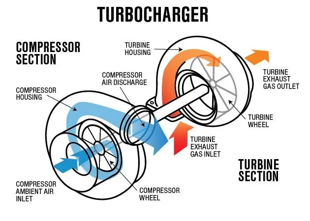
A turbocharger is a device fitted to a vehicle's engine that is designed to improve the overall efficiency and increase performance. A turbo is made up of two halves joined together by a shaft. On one side, hot exhaust gasses spin the turbine that is connected to another turbine which sucks air in and compresses it into the engine. This compression is what gives the engine the extra power and efficiency because as more air can go in the combustion chamber, more fuel can be added for more power.
PROCEDURE:
Step 1 -
The first step we need do is import the given geometry and do a geometry checkup to find out all the errors that are present in the imported geometry.
Geometry -
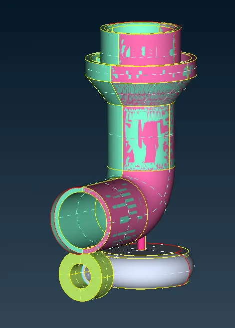
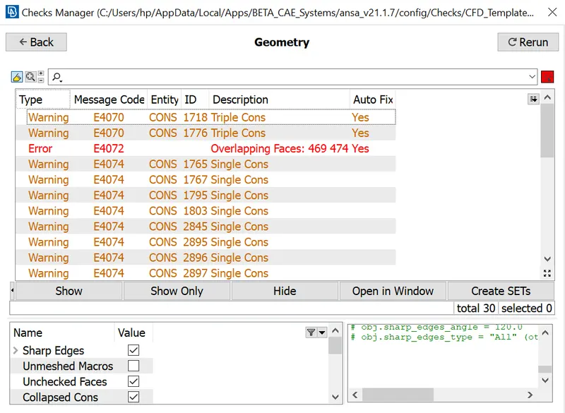
As we can see we have many single cones, gaps/open faces and overlapping surfaces in the geometry, ANSA counts all these as errors, as shown below after doing the geometry checkup also. So, the first thing we need to do is correct these errors.
Geometry checkup -
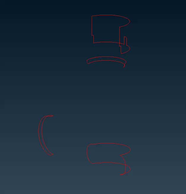
In order to see all the errors/single cons, we can turn off the shadow of the figure and turn off double and triple cons, so that we can see only single cons properly as shown below.
Single cons -
There are many ways to correct this error like; using "New Face" option, using "coons" option in surfaces or using "Fill Holes" option under cons. The option we're going to use id the "Fill Holes" option as it fills the holes in a surface without creating a new surface and hence give a better single surface rather than multiple surfaces.
After selecting the fill hole option all we need to do is select any hole as shown above and click the middle button of the mouse. We can do this for all the holes and we'll get a better geometry.
Overlapping Surfaces –
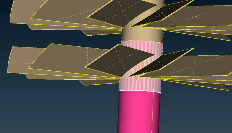
In order to delete the overlapping surfaces all, we need to do is delete the unnecessary surface. We’ll examine all the overlapping surfaces to see which surface to keep and which surface to delete.
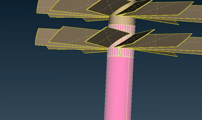
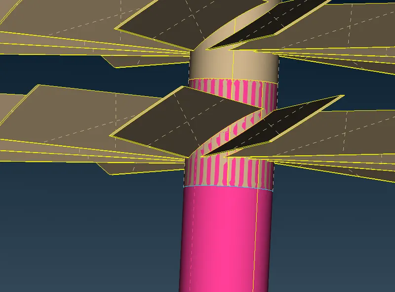
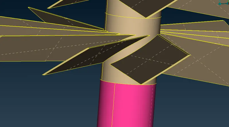
If while deleting an unnecessary surface the whole component is getting selected than all we need to do is create new coons around the intersecting area of two surfaces and we can do this by selecting the existing conns on a surface and projecting it on the other surface and then doing a “Topo” check to create a new three coon there and after that we can delete the overlapping surface and get a proper geometry.
Whole component getting selected –
Projecting cons and getting a triple coon there –
Overlapping surface selected –
Proper Surface -
Unnecessary surfaces –
If we see inside the Rotor shaft, we’ll see there are many unnecessary surfaces which will produce an error when we’ll try to do volume mesh and hence, we need to delete these surfaces before going for meshing.
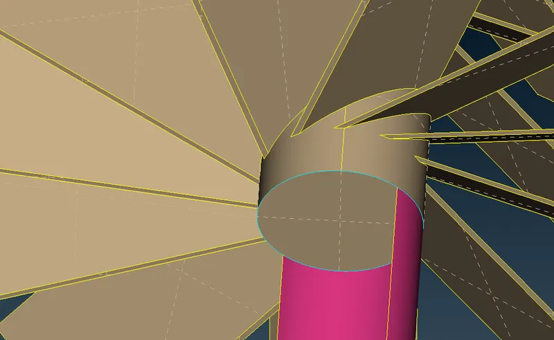
After deleting this area we'll have a hollow/single volume shaft.
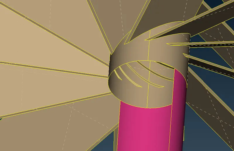
Properly Cleaned Geometry -
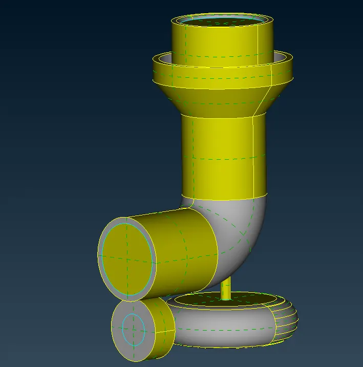
We can once again do the geometry check in order to verify the geometry.
Geometry checkup -
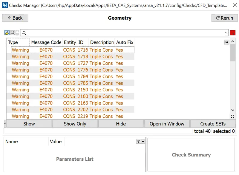
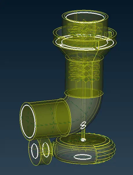
As we can see from above there are still some warnings, but these warnings are for triple cons and in order to create a water tight geometry for analysis we need these warnings and just proceed to next step.
Step 2 -
In this next step we'll divide the single PID model into several different PID in order to mesh the model more accurately and easily.
To create a new PID we'll open the PID manager, we'll add new PID by clicking on the "NEW" option present at the bottom options and under "NEW" option we'll select "Shell parameters".
We'll create 11 PID (as shown below) and in order to assign each PID to a component all we need to do is click on the PID and then click on apply, after the select the required part, you want to assign to the selected PID and press the mouse middle button.
The PID list and all the different PID are shown below.
Compressor casing with casing inlet and casing outlet –
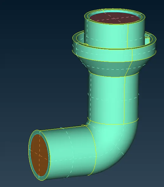
Turbo casing and bottom casing outlet –
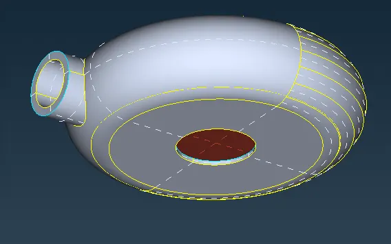
Inlet casing cover and bottom casing inlet –
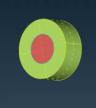
Impeller –
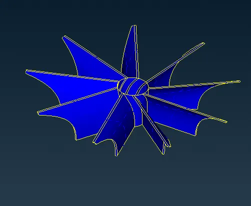
Shaft rotor –

Blade stage 1 & 2 -
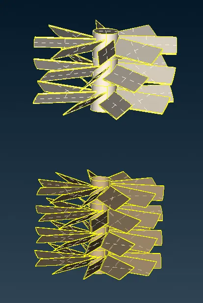
Full Geometry in PID mode –
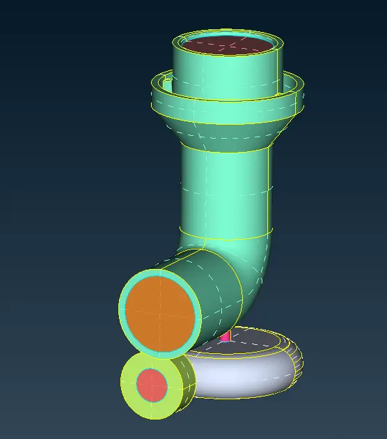
Step 3 -
Now we move to mesh mode from topo mode in order to mesh the given model.
The first thing we need to do is open the mesh parameters from the top option list and input the target length for the selected PID.
The target length for different PIDs is listed below
- Blade stage-1 = 1 mm
- Blade stage-2 = 1 mm
- Impeller = 2 mm
- Shaft rotor = 1 mm
- Turbo casing = 5 mm
- Compressor casing = 5 mm
- Inlet casing cover = 5 mm
We can mesh the given geometry by separating them by their target length.
Target length of 5mm –
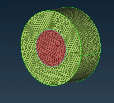
The PIDs with target length of 5mm are:
- Compressor casing
- Casing inlet
- Casing outlet
- Turbo casing
- Bottom casing outlet
- Bottom casing inlet
- Inlet casing cover
Above mentioned meshed elements –
Compressor casing with casing inlet and casing outlet –
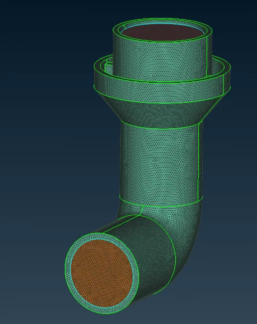
Turbo casing and bottom casing outlet –
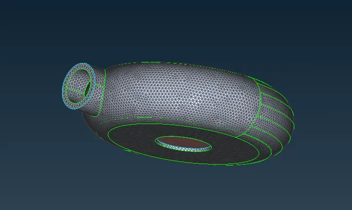
Inlet casing cover and bottom casing inlet –
Target length of 2mm –
The PIDs with target length of 2mm are:
- Impeller
Above mentioned meshed element –
Impeller -
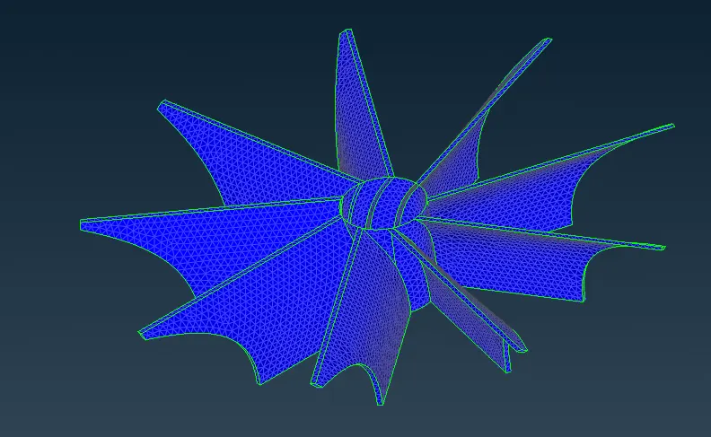
After meshing the impeller, we'll freeze this mesh so that we don't lose its mesh while we mesh the other PIDs. We'll do the same thing after meshing any PID.
Target length of 1mm –
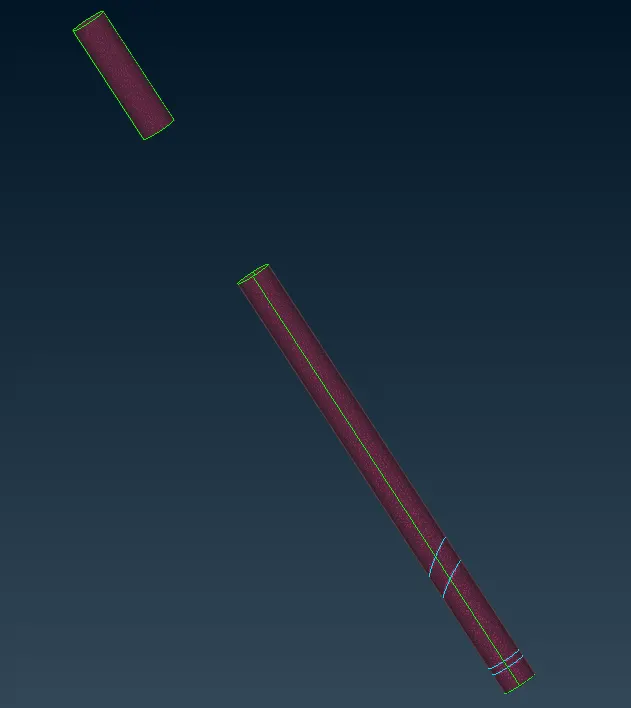
The PIDs with target length of 1mm are:
- Shaft rotor
- Blade stage 1
- Blade stage 2
Above mentioned meshed elements –
Shaft rotor –
Blade stage 1 & 2 -
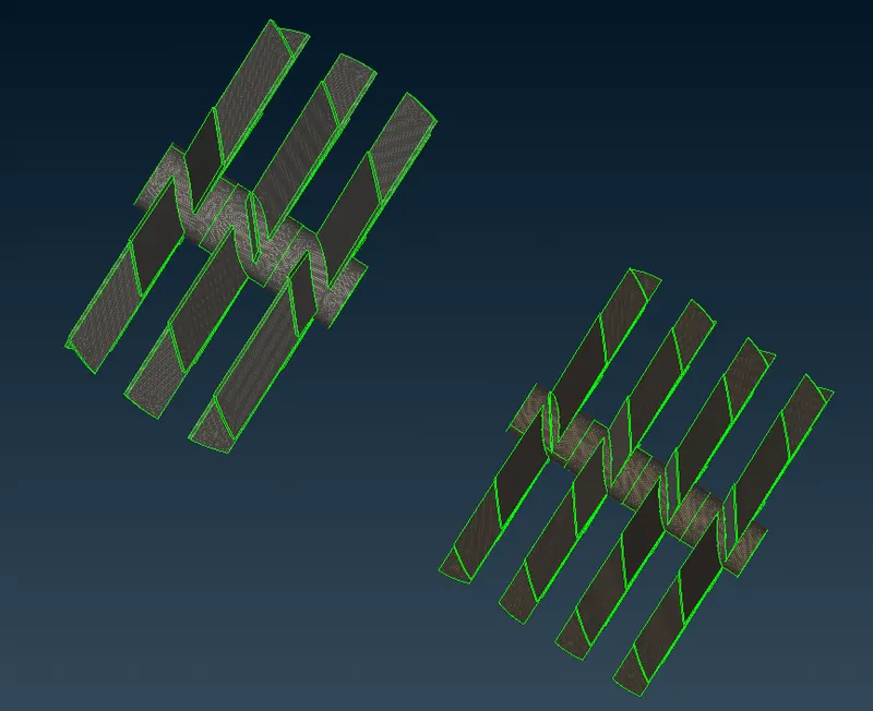
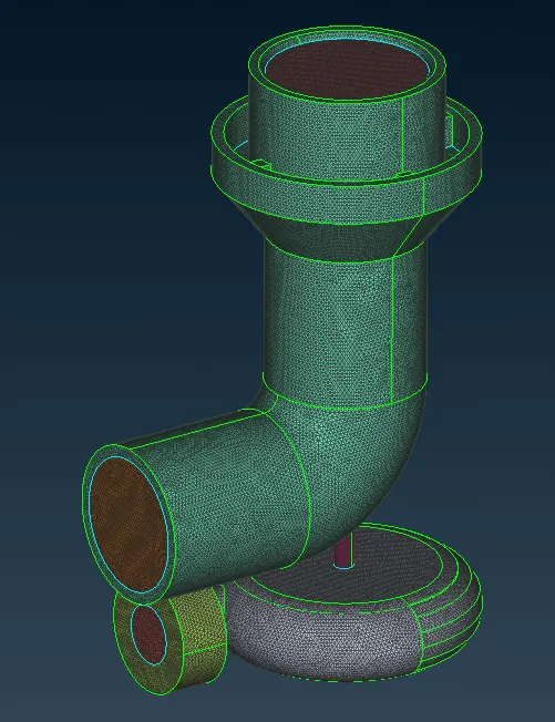
Full Meshed Geometry –
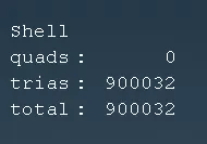
Number of surface mesh elements -
Now as we're done with surface meshing we can move to volume meshing.
Step 3 -
Volumetric mesh (3D) can be done only after surface (2D) meshing.
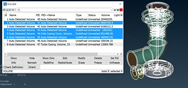
To check how many Volumes are available for volumetric meshing choose define option from volumes and then select the “Whole db” (db – data base) and click ok. This step will show PID's available for volumetric meshing. In our case we got 8 PID's.
Volumes available for meshing -
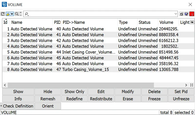
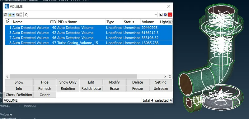
To check which PID's to keep and which to delete
- PID's which represents thickness of geometry are required to be deleted.
- PID's which represents volumes inside of geometry are required to be kept and these will be meshed.
Volumes to be deleted -
Volumes to keep -
Steps to do volumetric mesh
- Do right click on PID name and choose “Remesh” option from drop box.
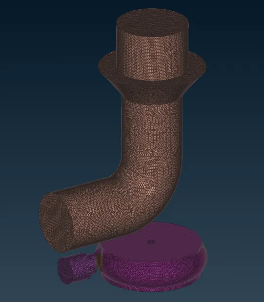
- After clicking on “Remesh” option, a pop-up-box will appear which will contain different types of meshing techniques. Choose the “Tetra CFD” option as we are doing CFD operation.
Generated Volumetric Mesh -
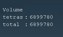
Number of volumetric mesh elements -
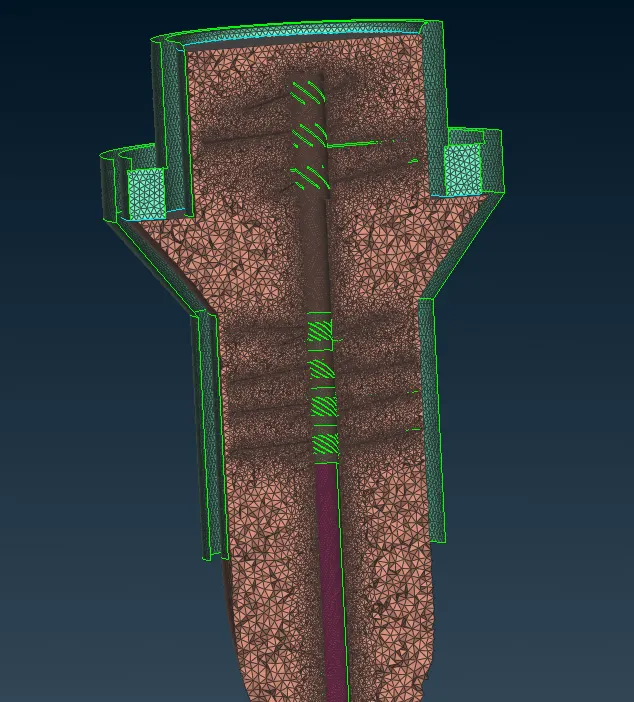
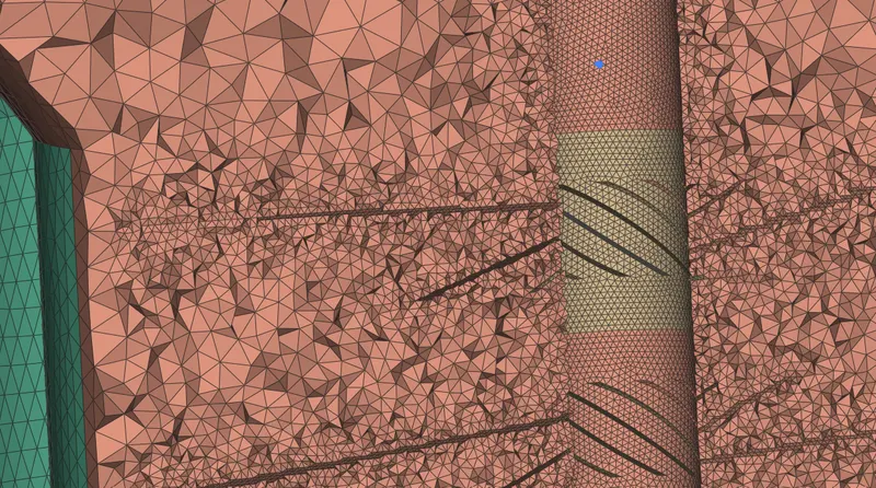
Cut view of the volumetric mesh -
ANSA Model file link -
https://drive.google.com/file/d/14WlxkXXrqPWMysUag4Lmkc5NlcwdwfKr/view?usp=sharing