Week 8 - Simulation of a backward facing step in OpenFOAM
OBJECTIVE – To simulate incompressible laminar viscous flow through backward-facing step geometry.
PROBLEM STATEMENT – Perform 2D transient incompressible laminar viscous flow through backward-facing step geometry using a suitable solver available in OpenFoam for the following cases.
Case 1 - Simulate the flow without using any grading factor (i.e., GF = 1).
Case 2 - Simulate the flow with a grading factor of 0.2. The cells should be finer near the walls (including the step wall).
Measure the velocity profile at 0.085 m from the inlet of the geometry for both case studies and compare.
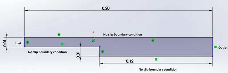
GEOMETRY – The geometry domain dimensions are given below along with boundary conditions.
SIMULATION SETUP –
1.) Mesh Generation –
To solve any simulation in OpenFoam, the first thing we need to do is to find a suitable tutorial from a tutorial file in OpenFoam and use the solver in that file to solve our problem.
The tutorial we’re choosing for our problem is the ‘Cavity’ tutorial located in the incompressible flow and the solver for this tutorial is ‘icoFoam’.
To start with the simulation, we first have to take out the selected tutorial to run folder in OpenFoam in order to edit the mesh and all other properties according to our problem.
The ‘Cavity’ folder contains files named ‘0’, ‘constant’, and ‘system’. Inside the ‘system’ file there’s a file named ‘blockMeshDict’ which contains information about the geometry of the problem and the mesh for that geometry.
We now edit the ‘blockMeshDict’ file in order to get the required geometry for our problem and also to get the mesh we want for our problem.
We’re going to create two types of mesh, one with GF=1 and the other with GF=0.2.
MESH for GF = 1
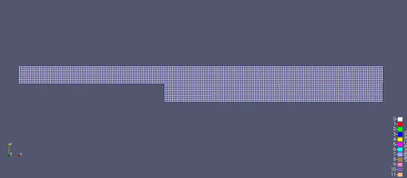
BlockMeshDict file for GF = 1
/*--------------------------------*- C++ -*----------------------------------*\
  =========                 |
  \\      /  F ield         | OpenFOAM: The Open Source CFD Toolbox
   \\    /   O peration     | Website:  https://openfoam.org
    \\  /    A nd           | Version:  8
     \\/     M anipulation  |
\*---------------------------------------------------------------------------*/
FoamFile
{
    version     2.0;
    format      ascii;
    class       dictionary;
    object      blockMeshDict;
}
// * * * * * * * * * * * * * * * * * * * * * * * * * * * * * * * * * * * * * //

convertToMeters 1;

vertices
(
    (0 0 0)
    (0.08 0 0)
    (0.08 0.005 0)
    (0 0.005 0)
    (0.08 0.01 0)
    (0 0.01 0)
    (0.20 0.01 0)
    (0.20 0.005 0)
    (0.20 0 0)
    (0.20 -0.01 0)
    (0.08 -0.01 0)

    (0 0 0.001)
    (0.08 0 0.001)
    (0.08 0.005 0.001)
    (0 0.005 0.001)
    (0.08 0.01 0.001)
    (0 0.01 0.001)
    (0.20 0.01 0.001)
    (0.20 0.005 0.001)
    (0.20 0 0.001)
    (0.20 -0.01 0.001)
    (0.08 -0.01 0.001)
);

blocks
(
    hex (0 1 2 3 11 12 13 14) (80 5 1) simpleGrading (1 1 1)
    hex (3 2 4 5 14 13 15 16) (80 5 1) simpleGrading (1 1 1)
    hex (2 7 6 4 13 18 17 15) (120 5 1) simpleGrading (1 1 1)
    hex (1 8 7 2 12 19 18 13) (120 5 1) simpleGrading (1 1 1)
    hex (10 9 8 1 21 20 19 12) (120 10 1) simpleGrading (1 1 1)
);

edges
(
);

boundary
(
    inlet
    {
        type patch;
        faces
        (
            (0 11 14 3)
            (3 14 16 5)
        );
    }
    outlet
    {
        type patch;
        faces
        (
            (9 8 19 20)
            (8 7 18 19)
            (7 6 17 18)
        );
    }
    frontAndBack
    {
        type empty;
        faces
        (
            (11 12 13 14)
            (14 13 15 16)
            (21 20 19 12)
            (12 19 18 13)
            (13 18 17 15)
            (0 3 2 1)
            (3 5 4 2)
            (4 6 7 2)
            (2 7 8 1)
            (1 8 9 10)
        );
    }
    NoSlipWall
    {
        type wall;
        faces
        (
            (5 16 15 4)
            (4 15 17 6)
            (10 21 12 1)
            (0 1 12 11)
            (10 9 20 21)
        );
    }
);

mergePatchPairs
(
);

// ************************************************************************* //
MESH for GF = 0.2
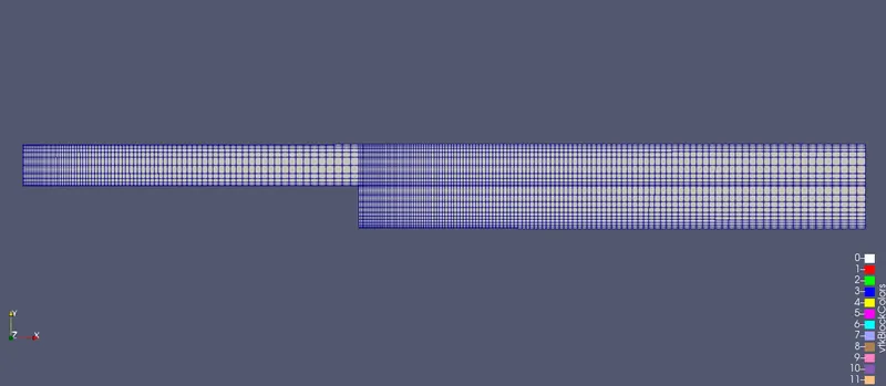
BlockMeshDict file for GF = 0.2
/*--------------------------------*- C++ -*----------------------------------*\
  =========                 |
  \\      /  F ield         | OpenFOAM: The Open Source CFD Toolbox
   \\    /   O peration     | Website:  https://openfoam.org
    \\  /    A nd           | Version:  8
     \\/     M anipulation  |
\*---------------------------------------------------------------------------*/
FoamFile
{
    version     2.0;
    format      ascii;
    class       dictionary;
    object      blockMeshDict;
}
// * * * * * * * * * * * * * * * * * * * * * * * * * * * * * * * * * * * * * //

convertToMeters 0.1;

vertices
(
    (0 0 0)
    (0.08 0 0)
    (0.08 0.005 0)
    (0 0.005 0)
    (0.08 0.01 0)
    (0 0.01 0)
    (0.20 0.01 0)
    (0.20 0.005 0)
    (0.20 0 0)
    (0.20 -0.01 0)
    (0.08 -0.01 0)

    (0 0 0.001)
    (0.08 0 0.001)
    (0.08 0.005 0.001)
    (0 0.005 0.001)
    (0.08 0.01 0.001)
    (0 0.01 0.001)
    (0.20 0.01 0.001)
    (0.20 0.005 0.001)
    (0.20 0 0.001)
    (0.20 -0.01 0.001)
    (0.08 -0.01 0.001)
);

blocks
(
    hex (0 1 2 3 11 12 13 14) (80 5 1) simpleGrading (5 5 1)
    hex (3 2 4 5 14 13 15 16) (80 5 1) simpleGrading (5 0.2 1)
    hex (2 7 6 4 13 18 17 15) (120 5 1) simpleGrading (0.2 0.2 1)
    hex (1 8 7 2 12 19 18 13) (120 5 1) simpleGrading (0.2 5 1)
    hex (10 9 8 1 21 20 19 12) (120 10 1) simpleGrading (0.2 5 1)
);

edges
(
);

boundary
(
    inlet
    {
        type patch;
        faces
        (
            (0 11 14 3)
            (3 14 16 5)
        );
    }
    outlet
    {
        type patch;
        faces
        (
            (9 8 19 20)
            (8 7 18 19)
            (7 6 17 18)
        );
    }
    frontAndBack
    {
        type empty;
        faces
        (
            (11 12 13 14)
            (14 13 15 16)
            (21 20 19 12)
            (12 19 18 13)
            (13 18 17 15)
            (0 3 2 1)
            (3 5 4 2)
            (4 6 7 2)
            (2 7 8 1)
            (1 8 9 10)
        );
    }
    NoSlipWall
    {
        type wall;
        faces
        (
            (5 16 15 4)
            (4 15 17 6)
            (10 21 12 1)
            (0 1 12 11)
            (10 9 20 21)
        );
    }
);

mergePatchPairs
(
);

// ************************************************************************* //
The above blockMeshDict file is executed using 'blockMesh' command to generate
the mesh and boundary types. The geometry with mesh can be viewed in Paraview
by executing the 'paraFoam' command.
2.) Initial and Boundary Conditions -
The initial and boundary conditions are next defined by editing the boundary files 'p'
and 'U' in the initial conditions folder (O).
Inlet:
Velocity - uniform - 1 m/s
Pressure - zero gradient
Outlet:
Pressure - uniform - 0 Pa.
velocity - zero gradient
Walls:
velocity - no-slip
Pressure - zero gradient
Front & Back:
velocity - empty
Pressure - empty
The corresponding files are given below
PRESSURE -
/*--------------------------------*- C++ -*----------------------------------*\
  =========                 |
  \\      /  F ield         | OpenFOAM: The Open Source CFD Toolbox
   \\    /   O peration     | Website:  https://openfoam.org
    \\  /    A nd           | Version:  8
     \\/     M anipulation  |
\*---------------------------------------------------------------------------*/
FoamFile
{
    version     2.0;
    format      ascii;
    class       volScalarField;
    object      p;
}
// * * * * * * * * * * * * * * * * * * * * * * * * * * * * * * * * * * * * * //

dimensions      [0 2 -2 0 0 0 0];

internalField   uniform 0;

boundaryField
{
    inlet
    {
        type            zeroGradient;
    }

    outlet
    {
        type            fixedValue;
        value           uniform 0;
    }
    NoSlipWall
    {
    	type             zeroGradient;
    }
    frontAndBack
    {
        type            empty;
    }
}
// ************************************************************************* //
VELOCITY -
/*--------------------------------*- C++ -*----------------------------------*\
  =========                 |
  \\      /  F ield         | OpenFOAM: The Open Source CFD Toolbox
   \\    /   O peration     | Website:  https://openfoam.org
    \\  /    A nd           | Version:  8
     \\/     M anipulation  |
\*---------------------------------------------------------------------------*/
FoamFile
{
    version     2.0;
    format      ascii;
    class       volVectorField;
    object      U;
}
// * * * * * * * * * * * * * * * * * * * * * * * * * * * * * * * * * * * * * //

dimensions      [0 1 -1 0 0 0 0];

internalField   uniform (0 0 0);

boundaryField
{
    movingWall
    {
        type            fixedValue;
        value           uniform (1 0 0);
    }

    fixedWalls
    {
        type            noSlip;
    }

    frontAndBack
    {
        type            empty;
    }
}

// ************************************************************************* //
3.) Solver Setup -
Transport Properties -
Since it is an incompressible laminar flow problem, the only equation solved is the
momentum equation. For this, we have to define the transport property kinematic
viscosity. For the present case, a fluid with kinematic viscosity(v = 0.01 m^2/s) is assumed. The transport properties are defined in the script file in the folder 'constant' and is given below:
/*--------------------------------*- C++ -*----------------------------------*\
  =========                 |
  \\      /  F ield         | OpenFOAM: The Open Source CFD Toolbox
   \\    /   O peration     | Website:  https://openfoam.org
    \\  /    A nd           | Version:  8
     \\/     M anipulation  |
\*---------------------------------------------------------------------------*/
FoamFile
{
    version     2.0;
    format      ascii;
    class       dictionary;
    location    "constant";
    object      transportProperties;
}
// * * * * * * * * * * * * * * * * * * * * * * * * * * * * * * * * * * * * * //

nu              [0 2 -1 0 0 0 0] 0.01;


// ************************************************************************* //
The solver 'icofoam', which is a transient incompressible laminar solver is used for solving the present case. The solver conditions are defined in the 'controlDict' file in the 'system' folder. The total time duration for the analysis is assumed to be 0.5 sec. The initial time, end time, timestep size are defined in this file. The time step decides the Courant number and stability of the solution and for a convective case it is given as:
`c = Udt/dx`
where C = Courant number;
U = maximum velocity in the flow field
dt = timestep size
dx = smallest mesh cell size
The courant number should be less than or equal to one to have a stable solution. The Courant number is assumed to be 0.01 to calculate the timestep for the solution to be stable.
The calculated time dt for C =0.01 and U = 2 m/s are:
1. Mesh with GF=1, dx = 0.001, dt = 5e-6;
2. Mesh with GF=0.2 , dx = 0.0002, dt = t = 1e-6;
The controlDict files for the two cases are given below:
ControlDict file -
/*--------------------------------*- C++ -*----------------------------------*\
  =========                 |
  \\      /  F ield         | OpenFOAM: The Open Source CFD Toolbox
   \\    /   O peration     | Website:  https://openfoam.org
    \\  /    A nd           | Version:  8
     \\/     M anipulation  |
\*---------------------------------------------------------------------------*/
FoamFile
{
    version     2.0;
    format      ascii;
    class       dictionary;
    location    "system";
    object      controlDict;
}
// * * * * * * * * * * * * * * * * * * * * * * * * * * * * * * * * * * * * * //

application     icoFoam;

startFrom       startTime;

startTime       0;

stopAt          endTime;

endTime         0.5;

deltaT          0.0005;

writeControl    timeStep;

writeInterval   20;

purgeWrite      0;

writeFormat     ascii;

writePrecision  6;

writeCompression off;

timeFormat      general;

timePrecision   6;

runTimeModifiable true;


// ************************************************************************* //
The solver scheme and solution script present in the system folder used by 'icoFoam' is given below:
fvScheme -
/*--------------------------------*- C++ -*----------------------------------*\
  =========                 |
  \\      /  F ield         | OpenFOAM: The Open Source CFD Toolbox
   \\    /   O peration     | Website:  https://openfoam.org
    \\  /    A nd           | Version:  8
     \\/     M anipulation  |
\*---------------------------------------------------------------------------*/
FoamFile
{
    version     2.0;
    format      ascii;
    class       dictionary;
    location    "system";
    object      fvSchemes;
}
// * * * * * * * * * * * * * * * * * * * * * * * * * * * * * * * * * * * * * //

ddtSchemes
{
    default         Euler;
}

gradSchemes
{
    default         Gauss linear;
    grad(p)         Gauss linear;
}

divSchemes
{
    default         none;
    div(phi,U)      Gauss linear;
}

laplacianSchemes
{
    default         Gauss linear orthogonal;
}

interpolationSchemes
{
    default         linear;
}

snGradSchemes
{
    default         orthogonal;
}


// ************************************************************************* //
fvSolution -
/*--------------------------------*- C++ -*----------------------------------*\
  =========                 |
  \\      /  F ield         | OpenFOAM: The Open Source CFD Toolbox
   \\    /   O peration     | Website:  https://openfoam.org
    \\  /    A nd           | Version:  8
     \\/     M anipulation  |
\*---------------------------------------------------------------------------*/
FoamFile
{
    version     2.0;
    format      ascii;
    class       dictionary;
    location    "system";
    object      fvSolution;
}
// * * * * * * * * * * * * * * * * * * * * * * * * * * * * * * * * * * * * * //

solvers
{
    p
    {
        solver          PCG;
        preconditioner  DIC;
        tolerance       1e-06;
        relTol          0.05;
    }

    pFinal
    {
        $p;
        relTol          0;
    }

    U
    {
        solver          smoothSolver;
        smoother        symGaussSeidel;
        tolerance       1e-05;
        relTol          0;
    }
}

PISO
{
    nCorrectors     2;
    nNonOrthogonalCorrectors 0;
    pRefCell        0;
    pRefValue       0;
}


// ************************************************************************* //
After defining the initial time, end time and time step size in the 'controlDict' file, the icoFoam' command is executed to run the analysis. After the analysis is carried up to the end time iteratively, 'paraFoam' command is used to post-process the analysis results in Paraview.
4.) Post-Processing -
The below plots show the velocity and pressure variation in the domain:
Velocity -
GF = 1
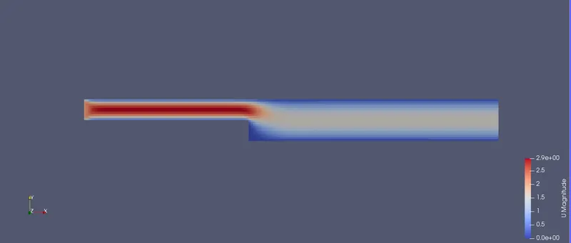
GF = 0.2
Pressure -
GF = 1
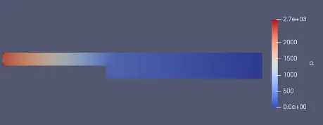
GF = 0.2
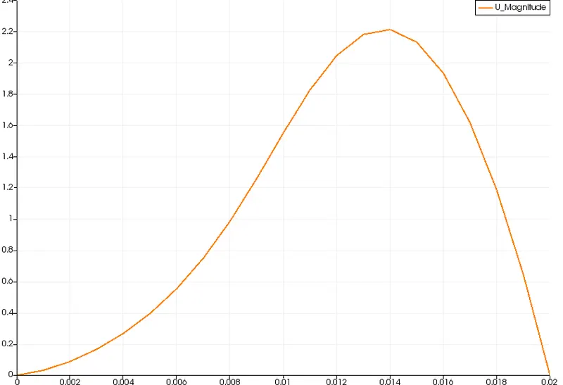
Velocity Variation at x = 0.085 m from inlet -
GF = 1
GF = 0.2
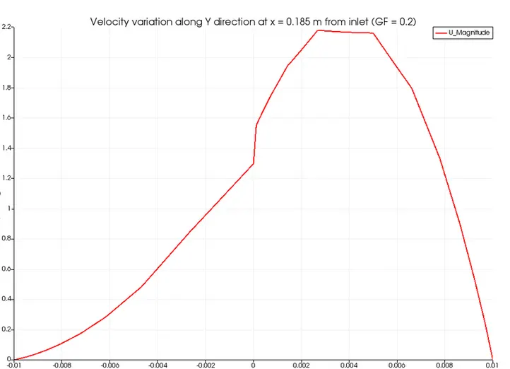
The above plots compare the velocity variation at x =0.085 m from the inlet, for both GF = 1 and GF = 0.2 cases. The velocity variation is smoother in the case of GF =1 when compared to the GF = 0.2 case. This is because the cells are uniform in the GF=1 case and in the case of GF=0.2, there were finer cells at the centerline and due to a gradual increase in cell size away from the centerline, sharp variations in velocity are observed.
Conclusion -
The velocity profiles in both cases are almost similar although different meshes are used. This is because the time duration considered for the analysis and the input velocity is very small. The effect of the grading factor on the results is negligible for the present problem. However, the grading factor influences the gradients and results in values at the boundaries. Fine cells should be used at the walls to accurately measure the gradients at the walls.