Week 3 Challenge : CFD meshing on Turbocharger
* OBJECTIVE
- Errors-free geometry to make appropriate volumes.
- Creating and assigning PIDs.
- Perform surface mesh with the given target lengths as per PIDs.
- Blade stage-1 = 1 mm
- Blade stage-2 = 1 mm
- Impeller = 2 mm
- Shaft rotor = 1 mm
- Turbo casing = 5 mm
- Compressor casing = 5 mm
- Inlet casing cover = 5 mm
- Performing volumetric mesh for required volumes.
* PROCEDURE
- Geometry Cleanup
perform geometry checks, Tools>Checks>Geometry function to identify and rectify errors such as problematic surfaces, single cons, trible cons, open edges, cracks, and overlapping surfaces.
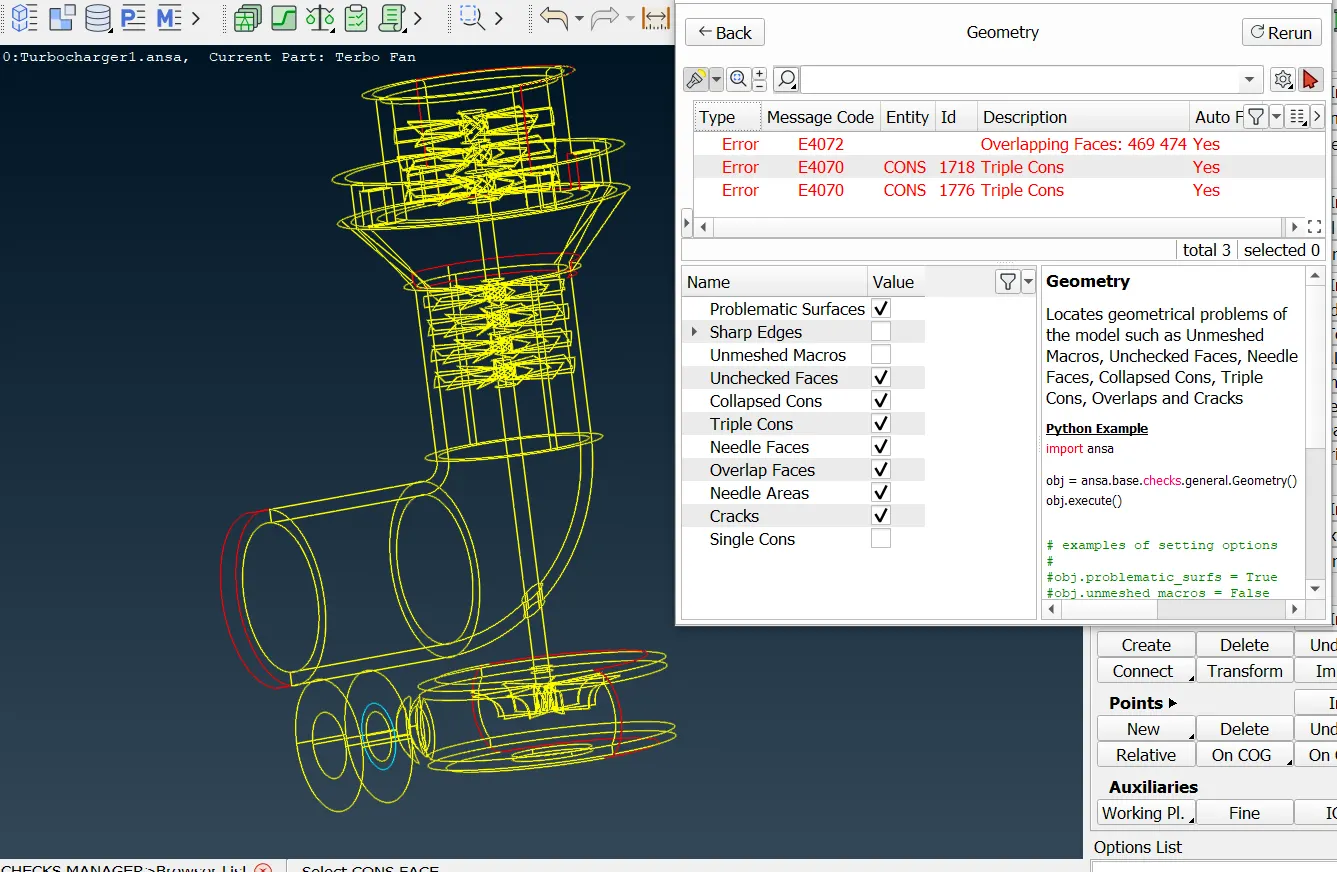
this image is before topological cleanup.
Activate the CONS>Paste function and select the CONS to be pasted, one after the other. Terminate the selection of CONS using the middle mouse button. All selected CONS are pasted to the last selected one.
Activate the Faces>Topo function and select the CONS, whose Topology has to be defined. Conclude the selection with the middle mouse button.
Use the Hot Points > Release function, which releases all pasted Hot Points. All CONS connected to the related Hot Points are released too.
the functions CONS > Release and Hot Points > Release provide similar results, except that CONS > Release may not be able to release some Hot Points.
The most common case is that unwanted triple or more CONS appear, This problem is solved easily by deleting the degenerate Face, using the Faces> Delete function.
Using the Utilities > Fine function from the TOPO or MESH module, one or more times, on the surrounding Faces, a more detailed morphology is achieved, and the collapsed CONS approaches its real shape.
Use the Faces > Cut function to trim the Face by creating a CONS between two selected Hot Points. The definition of a CONS by the Cut function is possible only if the two selected Hot Points lie on the same Face. The defined CONS is a straight line in the Face's 2D-parametric space.
Use the Faces > New function and select the EXISTING SURF type option. Select sequentially the CONS that will compose the perimeter of the new FACE. Activating the Loop selection allows auto-selection of all red CONS of the opening.
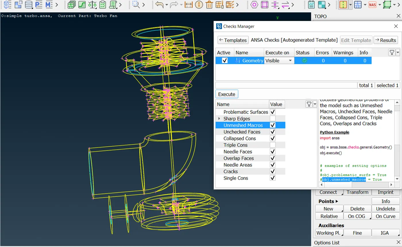
this image is .after topological cleanup.
- PID ASSIGNMENT
create Part ID for each component of the turbocharger
- Blade stage-1
- Blade stage-2
- Impeller
- Shaft rotor
- Turbo casing
- Compressor casing
- Inlet casing cover
- Compressor inlet
- Compressor outlet
- Turbo inlet
- Turbo outlet
assigning the created PIDs to the corresponding components in the geometry.
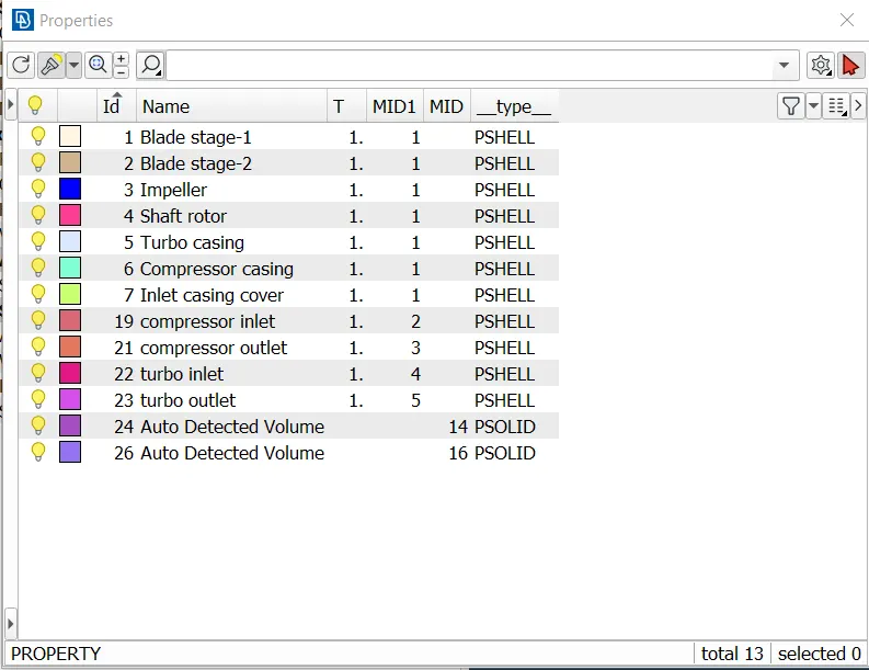
Assigning PIDs is crucial for effective meshing and analysis for several reasons such as Component identification, Mesh control, Boundary condition assignment, Material assignment, post-processing, and Visualization.
-SURFACE MESHING
Before surface meshing it is recommended to assign element length by perimeters>Length according to each PIDs.
Define target lengths for each PID based on the specification
- Blade stage-1 = 1 mm
- Blade stage-2 = 1 mm
- Impeller = 2 mm
- Shaft rotor = 1 mm
- Turbo casing = 5 mm
- Compressor casing = 5 mm
- Inlet casing cover = 5 mm
ANSA provides seven algorithms for shell meshing under the Mesh Generation Group of functions: Free, Map, Spot-Mesh, Adv.Front, CFD, STL, Gradual, 4 Sided and Circular.
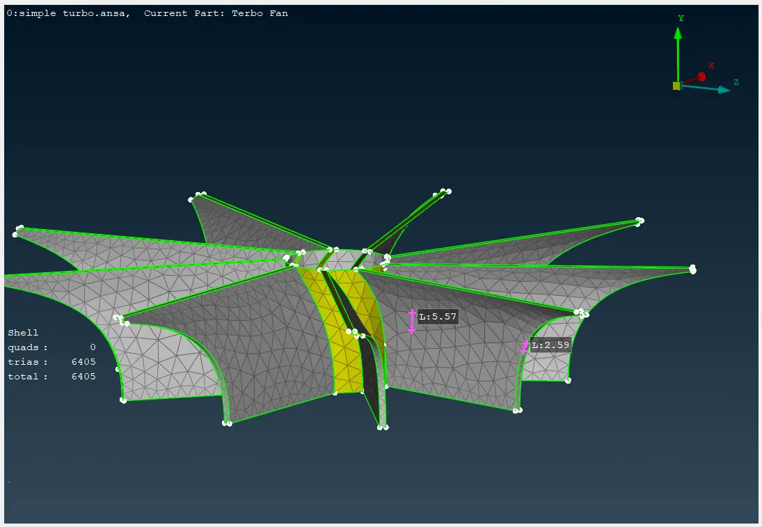
Here we trying to compare spot-mesh CFD meshing algorithms by meshing impeller PID which needs a target length of 2mm.
The Mesh Generation>Spot-Mesh algorithm generates more elements than the Free algorithm and brings better results to Macro Areas that have Weld or Connecting Spots on them.
By using spot mesh we get a refined mesh that has almost the same element length all over the area, so need more than 20000 shells for surface meshing.
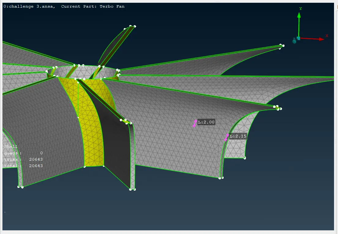
The Mesh Generation>CFD algorithm is an advanced meshing algorithm tailor-made to meet CFD specs or other application areas where a variable-size mesh is required.
By using CFD algorithm impeller surface meshing can be done by having 6405 shells.
- Volumetric meshing
Define the required volumes based on the analysis objectives and also choose a suitable volumetric meshing algorithm based on the desired mesh type and computational efficiency. Create volumetric mesh within the defined volumes using the generated surface mesh as a base.
For the definition of simple closed Volumes, the Volumes> Define function of the MESH menu is used.
Next, the Properties window opens to assign a PID for the Volume. The PID can also be assigned or modified later using the Volumes> Set PID function. In this sense, the concept of Volume is similar to the concept of Macro Area in shell meshing.
Depending on the way that solid mesh is created, the volume meshing algorithms can be divided into unstructured and structured mesh.
The available mesh generation algorithms are found under V.Mesh> Unstructured Mesh or at the MESH>Volumes> Mesh Vol. These algorithms are:
- Tetra Rapid: tetrahedral mesh (with pyramid elements if the starting surface mesh contains quad elements).
- Tetra FEM: tetrahedral mesh (with pyramid elements if the starting surface mesh contains quad elements) mainly for structural applications.
- Hexa Interior: a combination of hexa or penta layers all around the surface mesh, Cartesian hexahedral mesh with variable size inside the main volume, and a combination of tetra and pyramid elements in between.
- Hexa Poly: the combination of pyramids or tetras all around the surface mesh, Cartesian hexahedral mesh with variable size inside the main volume, and a combination of polyhedral and tetra elements in between.
we use The Tetra Rapid algorithm to give tetrahedral mesh, It is most suited for geometries of thick volumes or large domains with significant variation in the length of the surface mesh. Such geometries are mainly found in CFD applications.
* LEARNING OUTCOME
-TOPO>Faces>Intersect: The function can be used to easily find, isolate, and delete the unwanted/overlapped regions.
- TOPO>CONS>Release: Disconnect geometrical volumes that have been topologically pasted.
-TOPO>Faces>Topo: perform topology that two single cons to double cons or three single cons to trible cons.
-TOPO>Hot points>Multi Project: To project multiple hot points, 3D points, Weld spots, etc on Cons, Faces, and 3D curves.-TOPO>Hot points>Parametrical: Parametric definition of a Node on a 3D curve or Hot points on a curve.
-TOPO>Cons>Paste: The CONS to be pasted must lie opposite to each other and have similar length and morphology.
-TOPO>Auxiliaries> Fine: A similar effect as the change of the presentation resolution values can be achieved locally
-Utilities>Compress function: To reduce the size of the database. Under the GEOMETRY tree, there are the different entities (Faces, Curves, etc) that have been deleted but are still stored in the ANSA database for undelete. Activating their respective flag and pressing OK will remove them completely from the database.
-While Meshing two Different Target length entities make sure it is meshed with a smooth transition of target length
-All the functionality available for the handling and creation of solid elements is located under the MESH> VOLUME and the separate Volume Mesh module.
-For the definition of simple closed Volumes, the Volumes> Define[Detect on selected] function of the MESH menu is used.
-using Part Manager the user can place the new Volume entity in a Part
*RESULTS
-Geometry Quality:
complete topological cleanup of Problematic Surfaces, Sharp Angles, Unchecked Faces, Needle Faces, Collapsed Cons, Triple Cons, Overlaps, Cracks, and Single Cons. ensuring that by the status of checks Manager.
it's generally recommended to minimize the number of triple cons in the models whenever possible. This can be achieved through careful modeling practices, feature creation, and geometry cleanup techniques. If triple constraints are unavoidable, their impact should be carefully evaluated to ensure that they do not compromise the accuracy or reliability of the analysis.
-PID Assignment:
Assigning PIDs in ANSA is a fundamental step in creating a well-structured and efficient mesh for your analysis. It provides a clear organization, enables better control over meshing parameters, and facilitates the application of boundary conditions and materials.
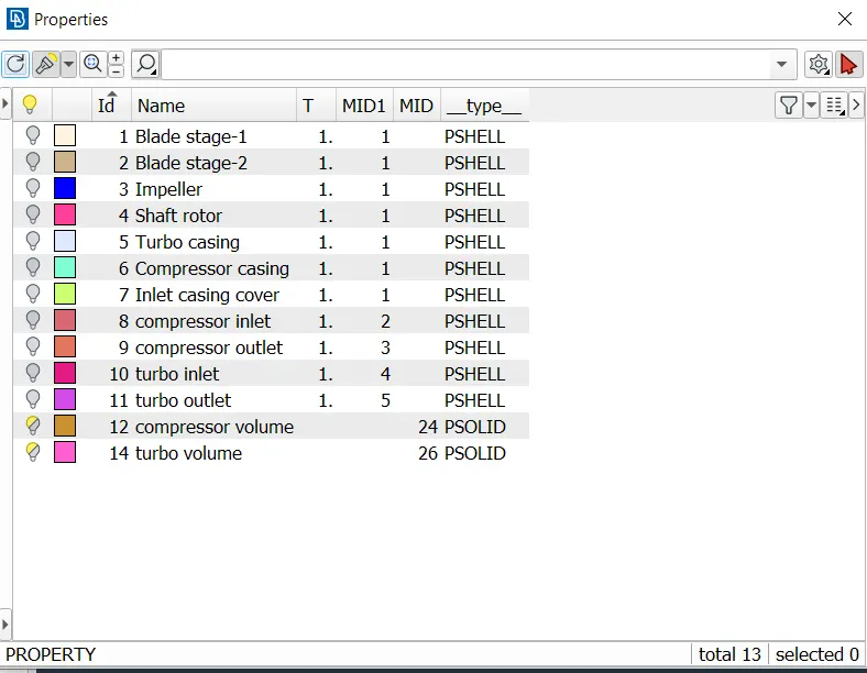
Here 14 PIDs are Created and assigned to their corresponding components including PIDs for volume mesh.
PSHELL Represents thin-walled structures like plates, shells, and membranes. PSOLID Represents solid bodies with a 3D volume.
-Surface Mesh Quality
Almost 767k trias-type elements are needed for surface mesh, based on the specified target length for each part.
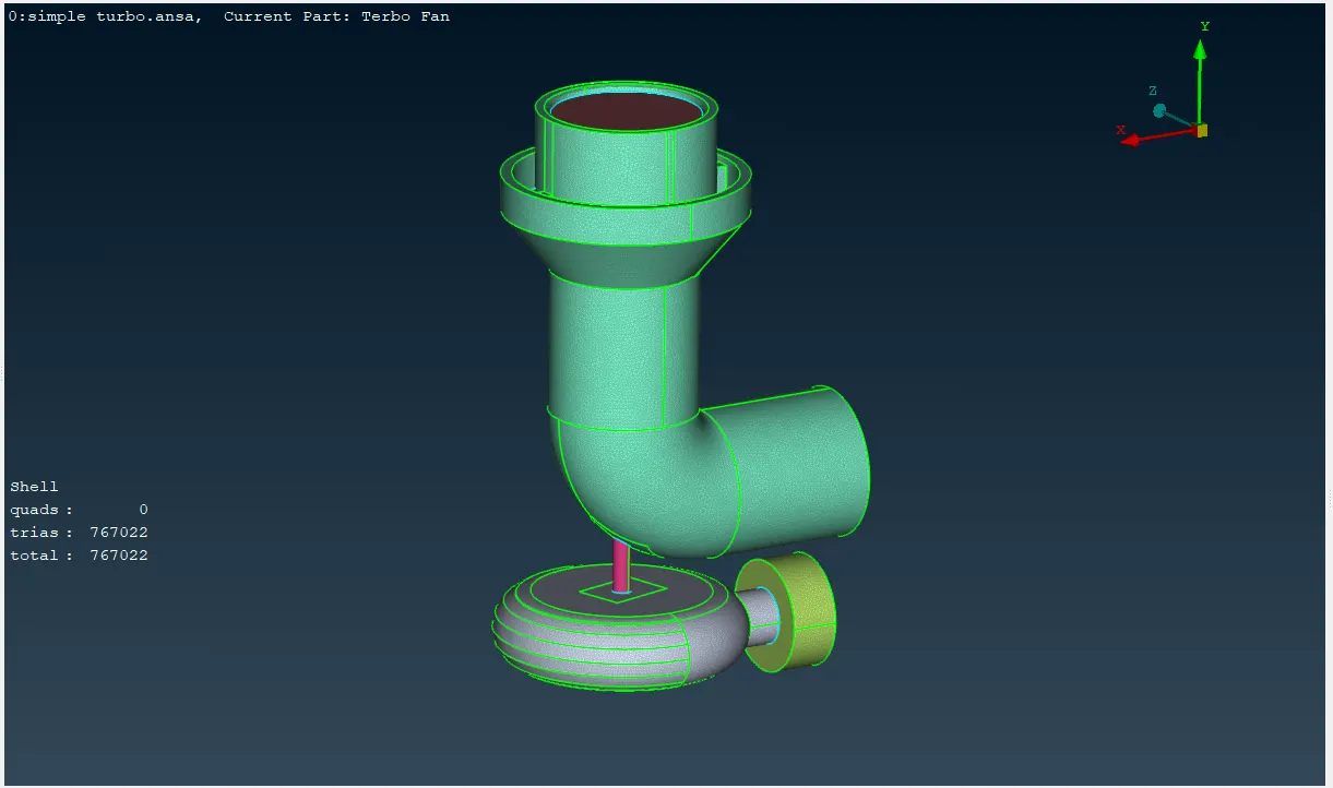
Due to the low target length and high quality of the mesh, needs high storage data and also needs to sacrifice the computational power while analysis. So it's generally recommended to minimize the number of elements by using appropriate target length and efficient meshing techniques.
-Volumetric Mesh Quality
Using tetra rapid volumetric mesh algorithm gives the tetrahedral mesh for trias type elements.
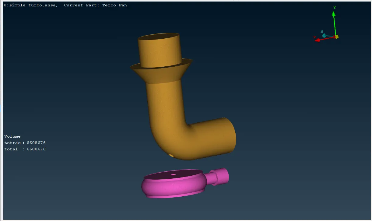
Here almost 6.6 million tetrahedral elements are needed for volumetric mesh. 66 million tetrahedral elements is a significant number for a turbocharger geometry, especially if it's a detailed model with multiple stages or complex flow paths.
*CONCLUSION
The project successfully generated a high-quality mesh for the turbocharger model, adhering to the specified target lengths and ensuring error-free geometry. The resulting mesh is suitable for subsequent analysis, such as Computational Fluid Dynamics (CFD) simulations.
In conclusion, 66 lakh tetrahedral elements is a substantial number, but it might be necessary if it involve high-speed, turbulent flows with complex interactions between the fluid and solid components. This can require a fine mesh to capture accurately. Computational resources, Flow physics, Desired Accuracy, and Geometry complexity are the factor that depends on the element count
While reducing the element count can improve simulation speed, it's essential to ensure that the resulting mesh is still able to capture the relevant flow physics.