Project 1 : CFD Meshing for Tesla Cyber Truck
Objective:
To mesh a Tesla Cybertruck model in ANSA, with an emphasis on geometry cleanup, PID assignment, mesh generation, and the application of symmetry. The goal is to produce a high-quality mesh for the model, utilizing appropriate target lengths and element quality criteria.
Procedure:
-Geometrical error correction
Import the car model's CAD file into ANSA. The initial step involves ensuring that the geometry is free of any topological errors that could hinder the meshing process.
The cleanup process can be simplified by cleaning one side of the model and then applying symmetry.
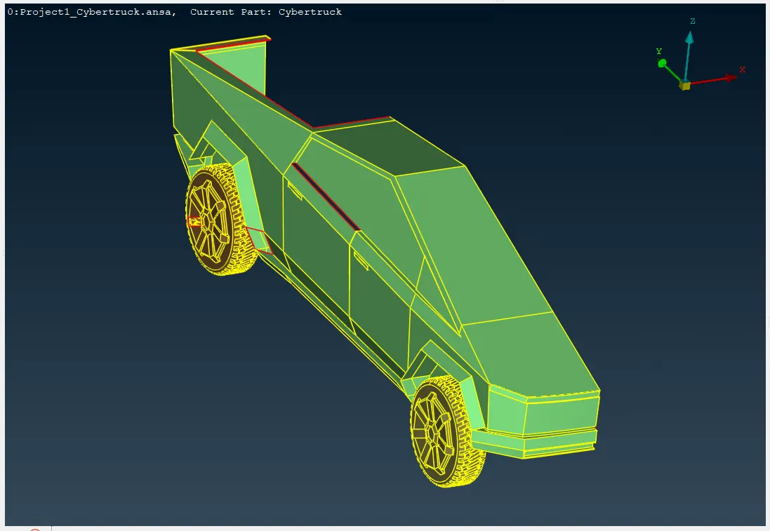
Visually examine the model for any inconsistencies, such as gaps, overlaps, or non-manifold edges. Use the software's tools to correct identified errors. This may involve creating surfaces, trimming edges, or rebuilding features.
The errors such as:
Non-manifold edges: Edges that belong to more than two faces.
Overlapping faces: Faces that intersect or overlap each other.
Self-intersecting surfaces: Surfaces that intersect themselves.
Gaps: Missing or incomplete faces that create voids in the model.
Incorrect surface normals: Inconsistent or incorrect orientations of surface normals.
Invalid surface parameters: Incorrect or invalid values for surface parameters.
Incorrect connectivity: Incorrect connections between edges, faces, and solids.
Duplicate geometry: Multiple instances of the same geometry.
This type of error can significantly impact the meshing process.
Here are a few errors I visually inspected.
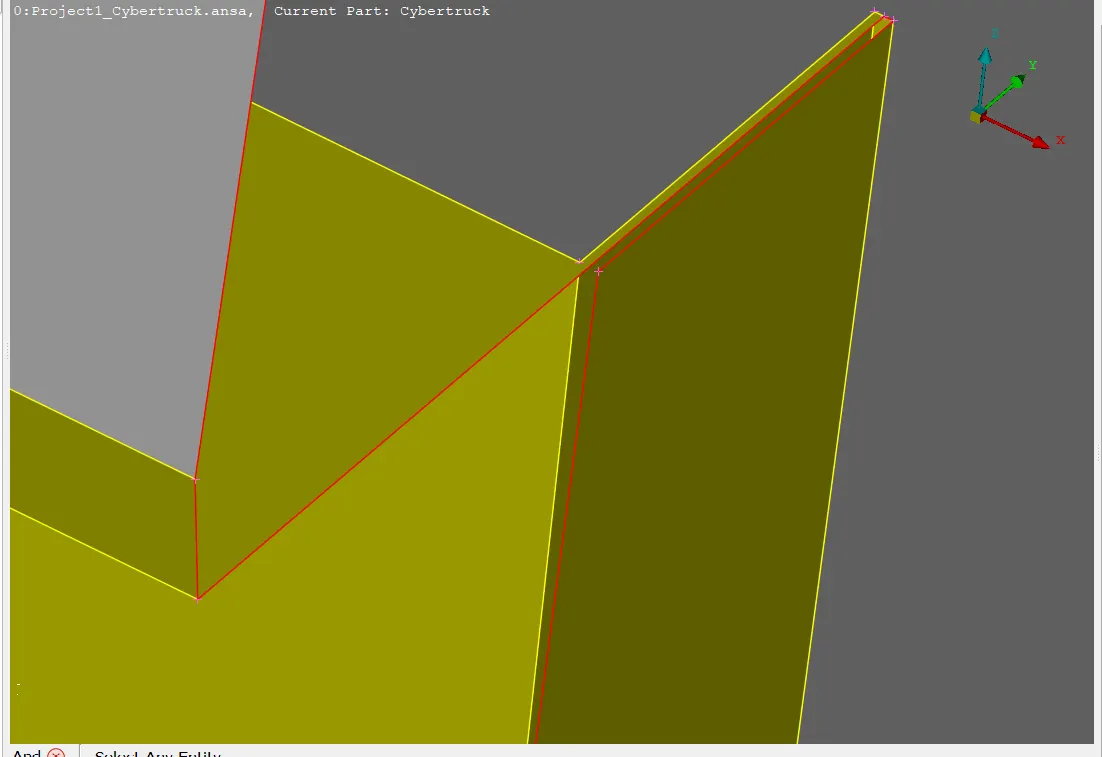
Unwanted or Incorrect surfaces, we can use face delete and cut operations to remove such errors.
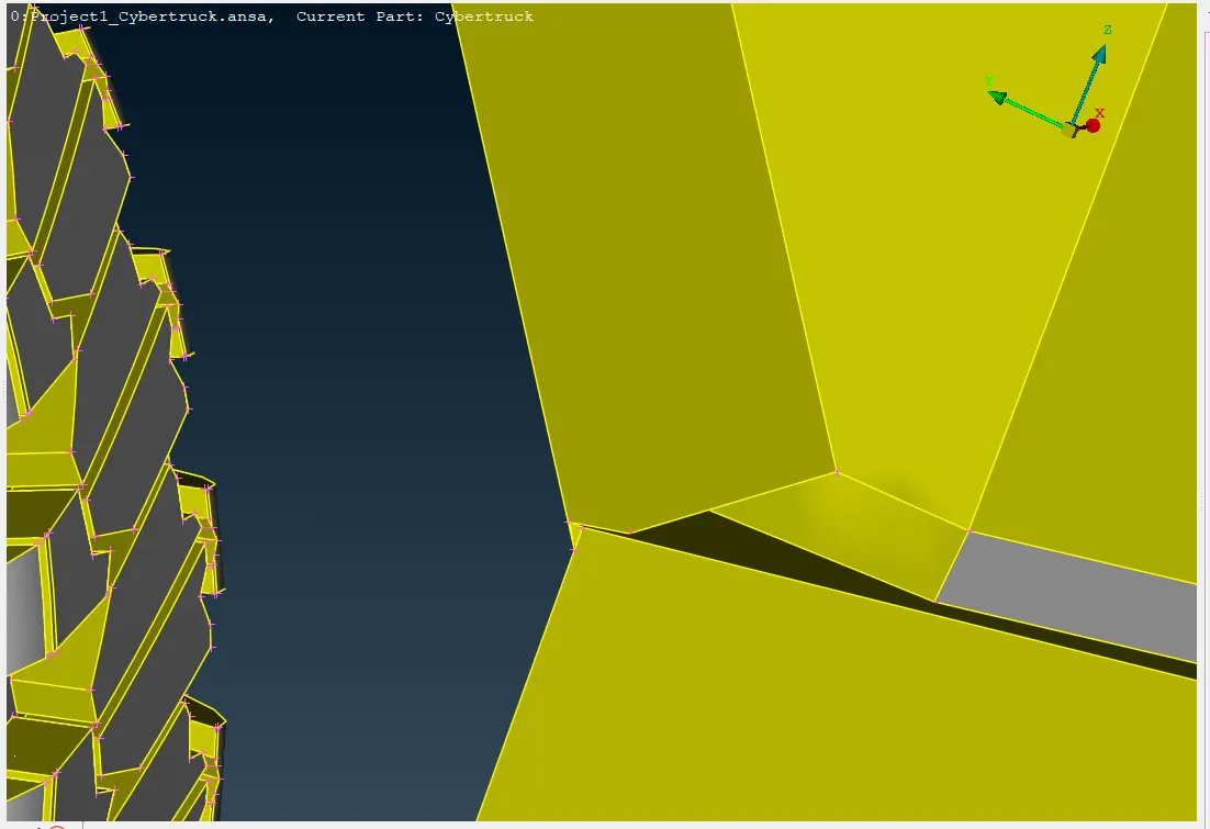
it is an Incorrect definition of the feature, we need to rebuild the feature for errors while meshing.
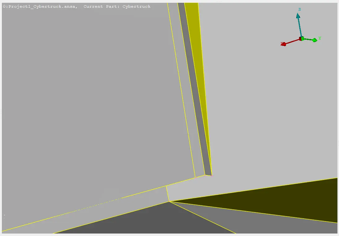
Cons that affect the skewness hhhhhhhzof the mesh element, can be reduced by avoiding sharp cons.
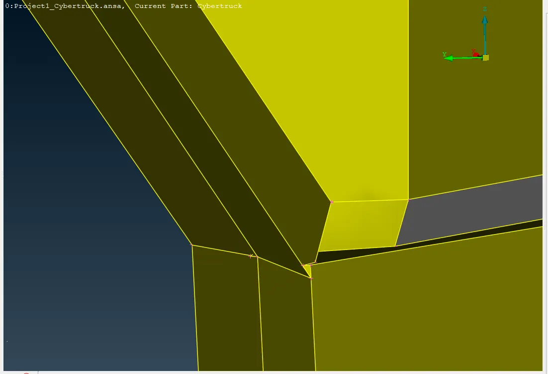
Incorrect connections between edges, faces, and solids, we need to Rebuild components and make correct appropriate connections.
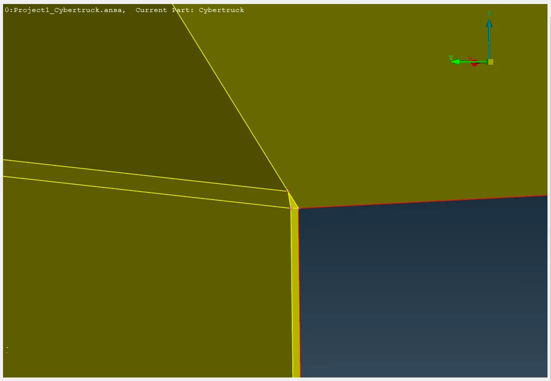
Unwanted faces in connection, resolving incorrect connections between edges and faces.
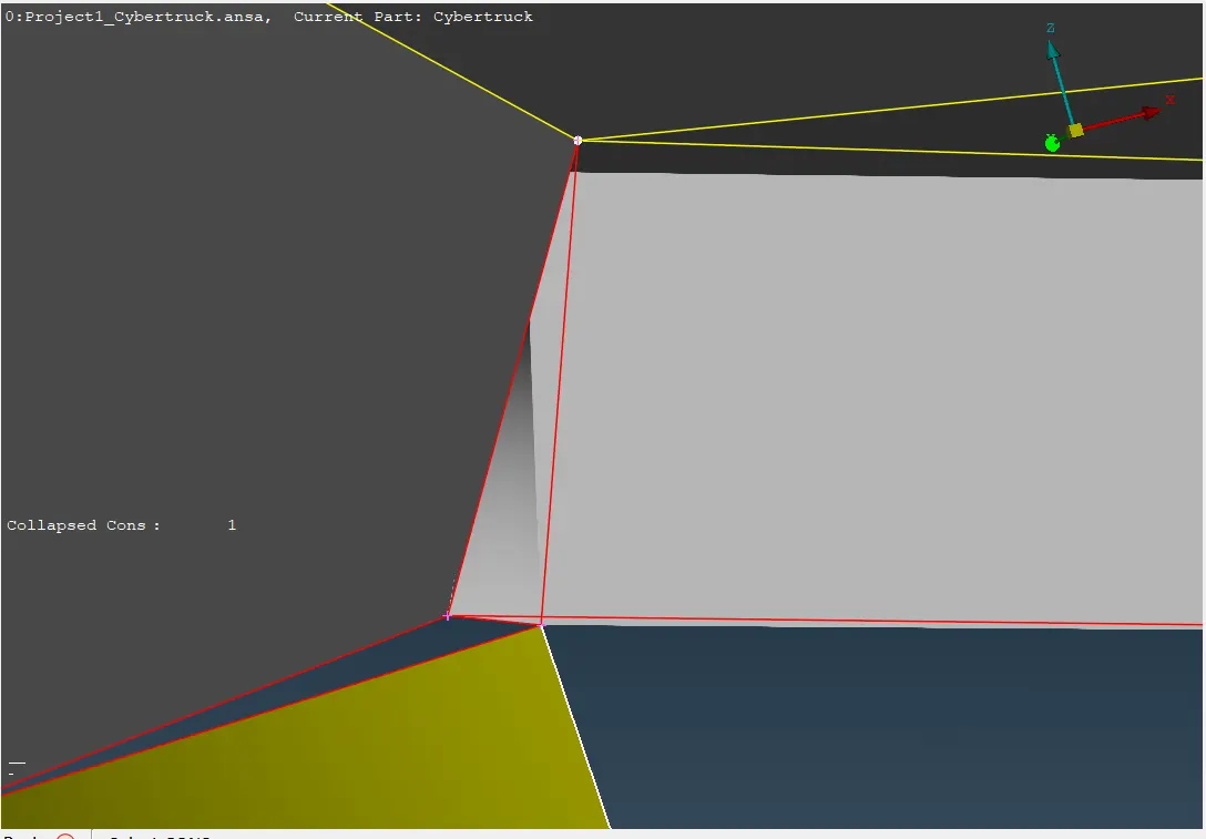
Missing or incomplete faces create voids in the model, we need to rebuild the faces to resolve that.
perform geometry checks, Tools>Checks>Geometry function to identify and rectify errors such as problematic surfaces, single cons, trible cons, open edges, cracks, and overlapping surfaces.

Complete the topological cleanup by addressing problematic surfaces, sharp angles, unchecked faces, needle faces, collapsed edges, triple edges, overlaps, cracks, and single edges, and ensure the status checks manager verifies all.
-PID assignment
PIDs offer a structured approach to mesh frameworks, simplifying the management, analysis, and interpretation of results.
Different Properties may be assigned to different Faces, either directly from the CAD file or during the ANSA session. By default, in ENT view mode, the Faces are colored gray and yellow, on their positive and negative side, respectively. Switching to PID view mode, the Faces are colored according to their PID. To modify the Property of Faces, activate the function Faces>Set PID.
To assign PIDs go to the PID section and create a new PIDS and right click select apply then select the components for which you want to create PIDs.
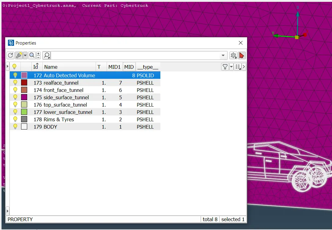
Here 8 PIDs are Created and assigned to their corresponding components rims and tyres pid for 4 wheels, one for body, and the other 4 PIDs for wind tunnel and one for volume mesh.
-Meshing
ANSA provides seven algorithms for shell meshing under the Mesh Generation Group of functions such as Free, Map, Spot-Mesh, Adv.Front, CFD, STL, Gradual, 4 Sided and Circular.
For CFD analysis and simulation, it's generally recommended to minimize the number of elements by using an appropriate target length and efficient meshing techniques. However, a low target length and high-quality mesh require significant data storage and computational power during analysis.
here is an example
if we use STL algorithm The Mesh Generation>STL algorithm can be used for applications where the quality of the elements is not very important but the exact geometry representation is. This algorithm must be used in combination with the Spacing [Auto STL] .
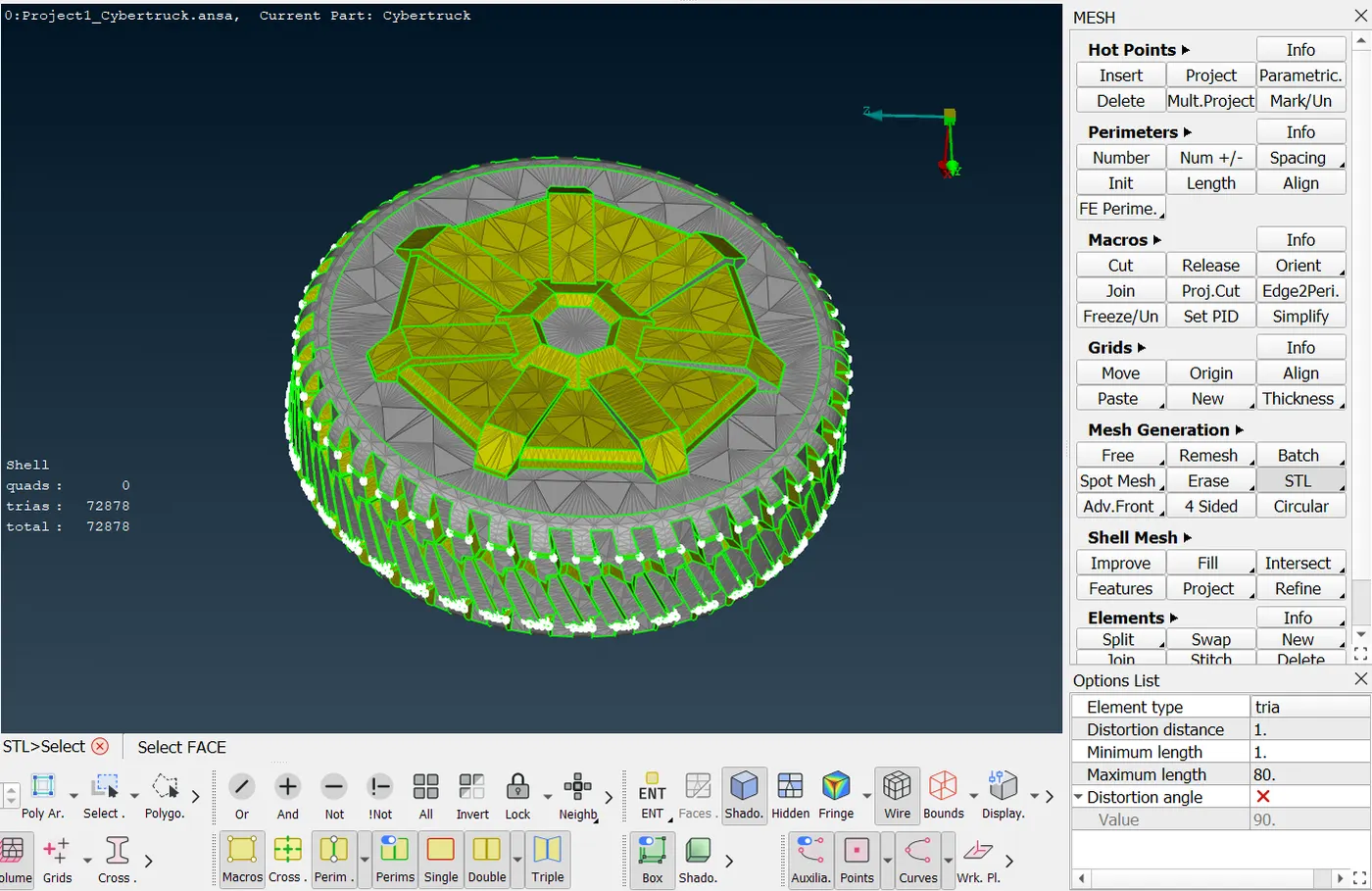
The entire rims & tire can be meshed using fewer than 80,000 shells; however, the mesh is unsuitable for analysis and simulation due to its poor quality.
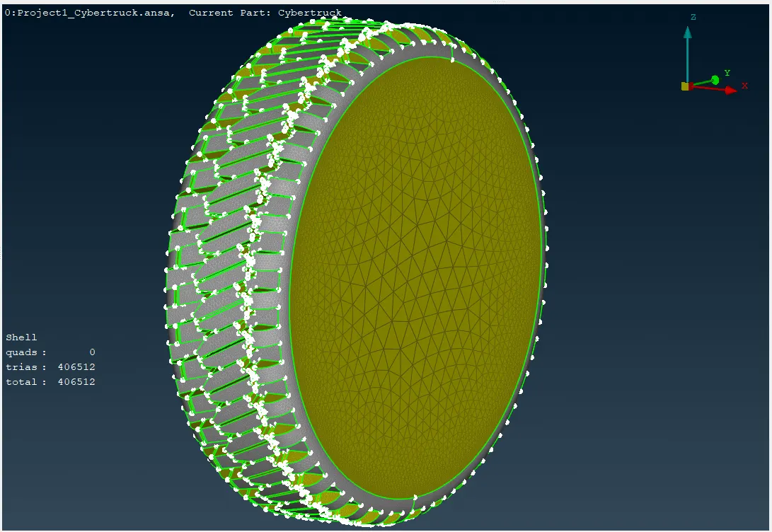
Here, the rims and tires have been meshed using approximately 400,000 shells, resulting in a mesh that is well-suited for analysis and simulation. Choosing a CFD algorithm for meshing the entire body is advantageous because Meshing with the CFD function results in a high-quality mesh, refined according to the local surface curvature and the specified max allowed distortion angle of the mesh.
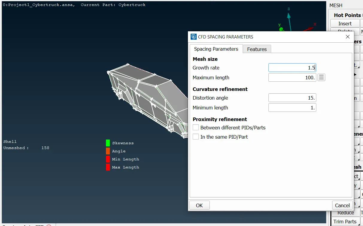
In order to mesh with the CFD algorithm, it is recommended to use the Perimeters>Spacing [Auto CFD] function first and assign nodal spacing on the model. Here we select the maximum length as 100 and growth rate as 1.5 and the distortion angle as 15.
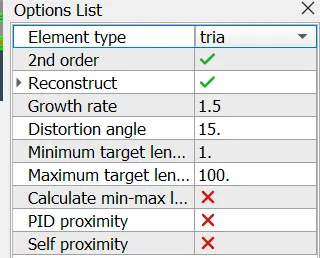
When meshing with CFD algorithms, the process should be under tight user-controlled specification controlled specifications. so double-check the Options List window before meshing.
After meshing, it is necessary to check the quality of the mesh elements. If there are any defective elements, we need to isolate and re-mesh them. Reconstruction is a powerful algorithm for the creation of a high-quality surface mesh. It is applied on an existing mesh and performs re-meshing. Reconstruct also has embedded the Fix Quality functionality, so any problems that cannot be fixed by re-meshing, are automatically fixed by nodal movements. nodal movements can also be performed while in Hidden View mode with the respective quality criteria check boxes enabled so that the element quality is monitored and displayed during the node movement.
The symmetry function is used to create or move symmetrical entities using the current symmetry plane. To activate this, go to Utilities > TRANSF. > LINK function. Select the desired entities using the left mouse button and confirm your selection with the middle mouse button. The 'Link - Entities' window will appear. Press 'Apply' to continue. Ensure that the symmetry operation has been executed properly and that the complete model is free of geometric inconsistencies.
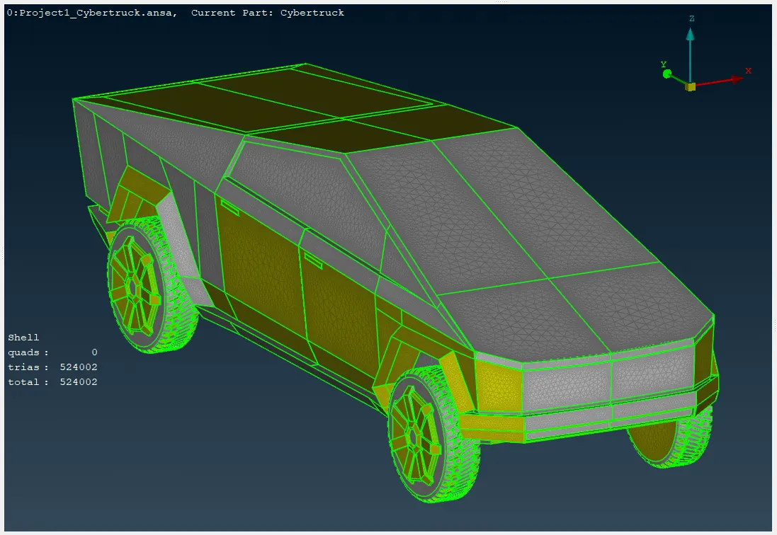
Within 524k trias-type elements, the entire body is meshed using CFD algorithm.
next step is volume mesh for that we need to create a wind tunnel. The wind tunnel is used to simulate the aerodynamic forces and pressures that a car experiences while moving. Create a simple, box-shaped geometry representing the wind tunnel. Ensure the dimensions are large enough to accommodate the car and allow for proper airflow development.
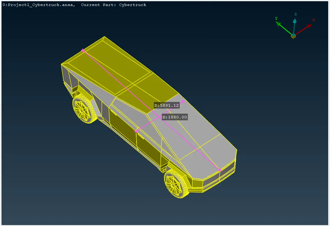
The first step is to measure the length and width of the truck to ensure the wind tunnel is constructed according to those dimensions.
The TOPO>POINTS>RELATIVE and TOPO>CREATE>CURVE options can be utilized to construct the wind tunnel structure, while the TOPO>FACES>NEW option is used to create the planar face.
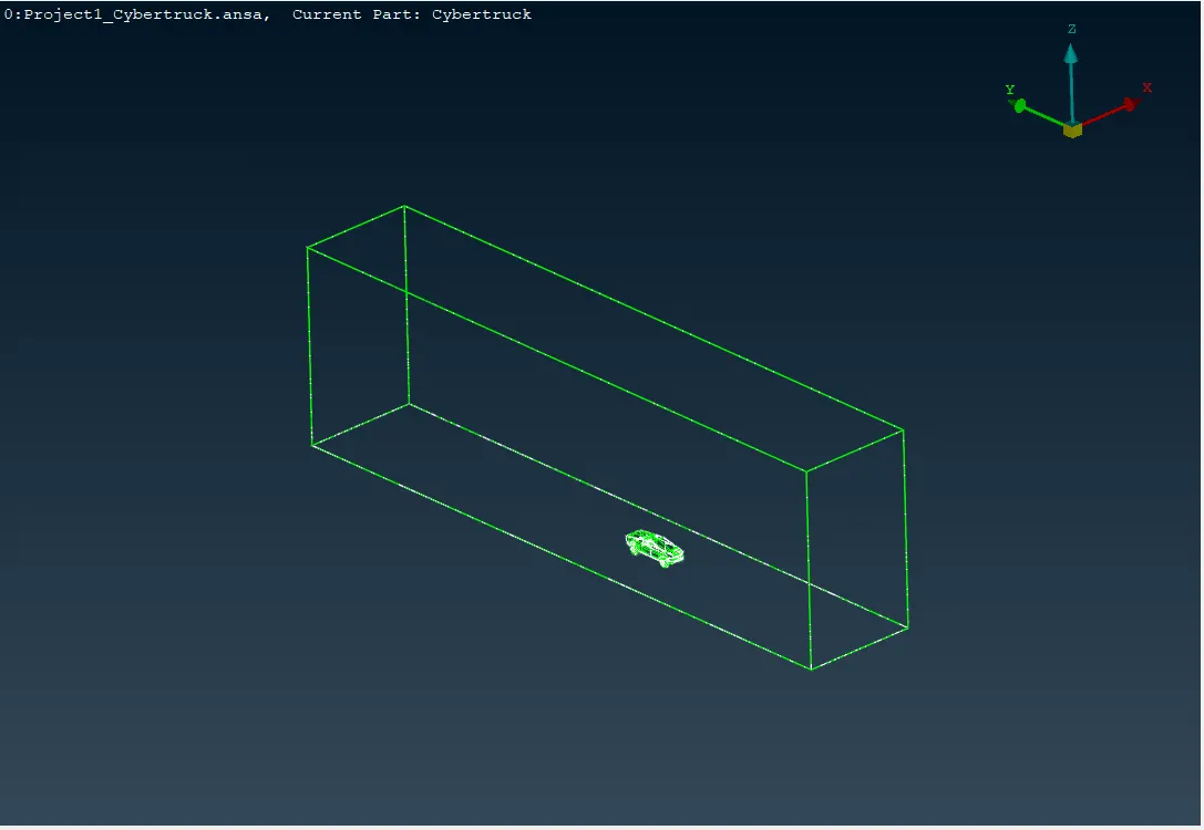
We can use the spacing option for wind tunnel, Perimeters> Spacing function can be used to automatically assign proper element length and nodal distribution on Perimeters to capture details and minimize computational cost.
The target length for the upper side of the wind tunnel is 1000, and for the lower side, it is 200, with a smooth transition in length on the side surface achieved by using the spacing option.Using the spacing function, the element length increases from 200 to 1000, starting from the bottom and going to the top.
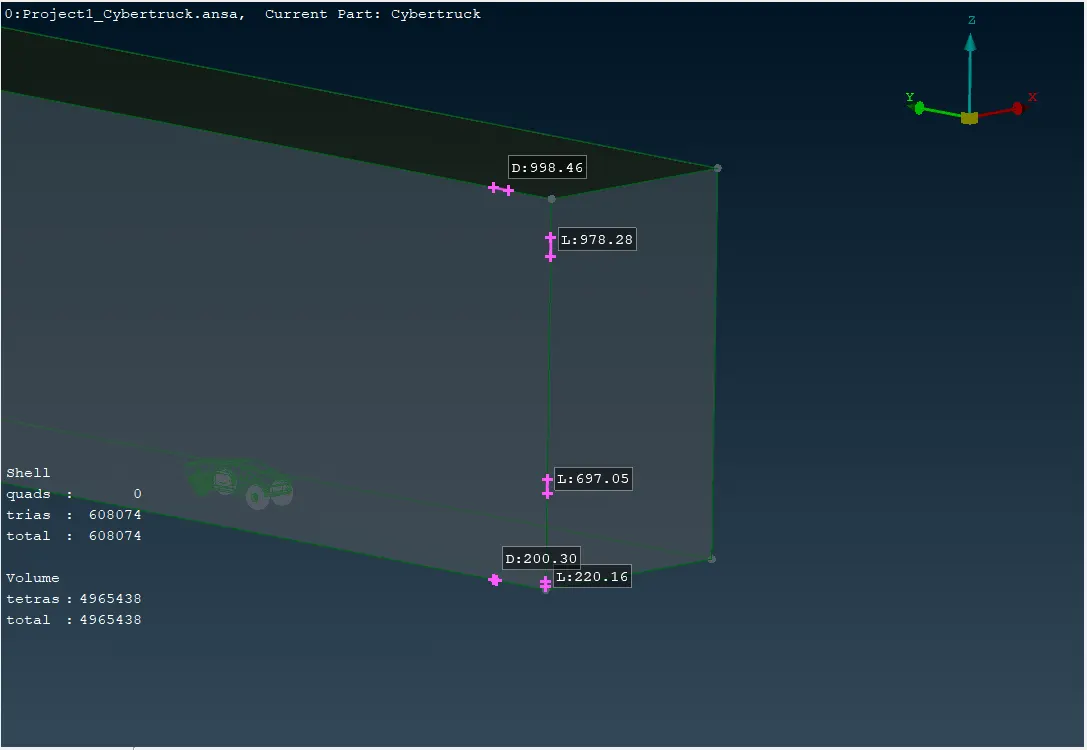
Approximately 524K trias-type elements are required for the surface mesh of the car, When including the wind tunnel, less than 5 million shells are needed.
LEARNING OUTCOME:
-The CFD algorithm is sensitive to the local curvature. Any problems in the quality of the CAD data, the topology, and the joining of sharp angle Perimeters that lead to steep curvature discontinuities may cause mesh failure.
-The CFD function grows the mesh size on flat Macros. If a constant mesh size is desired on selected Macros the Adv.Front algorithm can be applied instead.
-The Mesh Generation>STL algorithm can be used for applications where the quality of the elements is not very important but the exact geometry representation is. This algorithm must be used in combination with the Spacing algorithm.
-Reconstruction is a powerful algorithm for the creation of a high-quality surface mesh. It is applied on an existing mesh and performs re-meshing. Reconstruct also has embedded the Fix Quality functionality, so any problems that cannot be fixed by re-meshing, are automatically fixed by nodal movements.
-nodal movements can also be performed while in Hidden View mode with the respective quality criteria check boxes enabled so that the element quality is monitored and displayed during the node movement.
- Actions>Transform from the context menu of the Parts/Groups in the main section of the Model Browser window, the user can alter the position of selected Parts/Groups by applying a series of actions such as Translate, Rotate, Transform, Scale, Symmetry or Mirror.
-A wind tunnel is a testing facility used to study the effects of airflow past an object, This will allow you to examine the aerodynamic forces, drag, lift, and other relevant parameters that influence a car's performance.
- For the wind tunnel volume, consider using a coarser mesh initially to reduce computational time. If necessary, refine the mesh in specific regions of interest later.
RESULTS:
Corrected Model - Complete removal of geometric errors or inconsistencies that might hinder the meshing process by the long process of geometry clean-up.
Assigned PIDs - Here 8 PIDs are Created and assigned to their corresponding components including PIDs for wind tunnel and volume mesh. PSHELL Represents thin-walled structures like plates, shells, and membranes. PSOLID Represents solid bodies with a 3D volume.
High Quality Mesh - Approximately 524 K trias-type elements are required for the surface mesh of the car. When including the wind tunnel, less than 5 million shells are needed.
Confirm the successful application of symmetry and the absence of any geometric errors in the complete model. In this process, we integrate skewness, minimum and maximum length, and angle quality criteria, coupled with fluent calculation algorithm. Finally, achieve a state where no elements violate the quality criteria by utilizing approximate meshing algorithms and functions.
CONCLUSION:
The project successfully achieved its objectives by identifying and correcting geometrical errors, assigning appropriate PID controllers, and generating a high-quality mesh. The resulting model is well-suited for further analysis and simulation.
project link:
https://drive.google.com/file/d/1ADuK2lRDvMdJz9l0zUmW0QKpORex0W3g/view?usp=sharing