Week 3 Challenge : CFD meshing on Turbocharger
AIM:
To study and perform the surface meshing and volumetric meshing on the turbocharger model.
OBJECTIVE:
Our motto in this report is to check for geometrical errors to make sure appropriate volumes are present. To create PIDs and assign them accordingly based on the parts of a turbocharger. Finally to perform the surface mesh for the given target length of each and every part mentioned also perform volumetric mesh for the required volumes.
TOOLS USED:
- FILL HOLE
- HOT POINTS(INSERT)
- TRANSFORM(SYMMETRY)
- TOPO
- CONS(PROJECT)
- DELETE
- FACE(FITTED)
- FACE(PLANNER)
- PERIMETER(LENGTH AND MACROS)
- SPOT MESH
- UNFREEZE
- VOLUME(DEFINE)
- TETRA RAPID
PROCEDURE:
- Firstly we open the CAD model by browsing the location.
- We get the turbocharger model as shown below with geometrical errors and intersection errors.
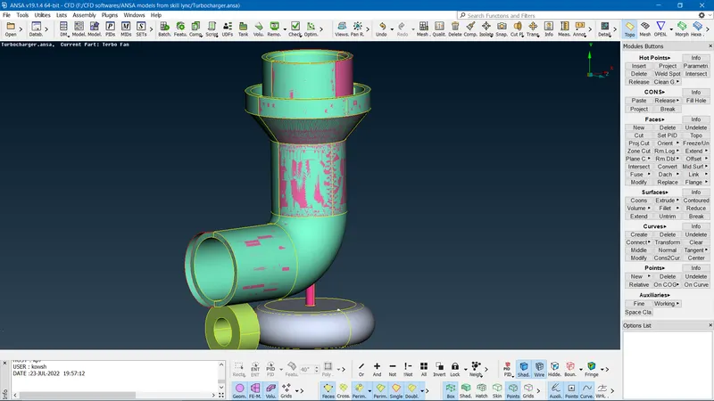
- In the above image, we can see the pink and green surface which is due to the surface overlapping causing a geometrical error.
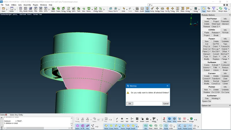
- The above error can be taken care of by selecting each and every pink color entity(ENT) option==>use the delete option to delete the surfaces.
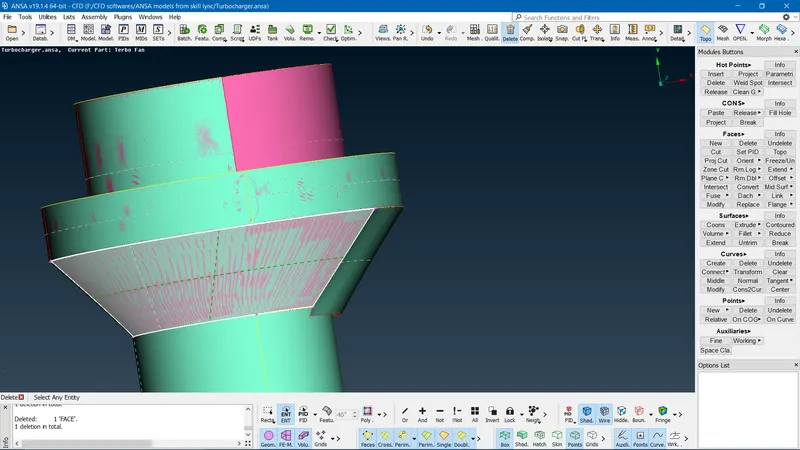
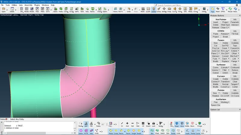
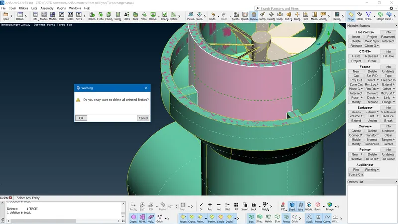
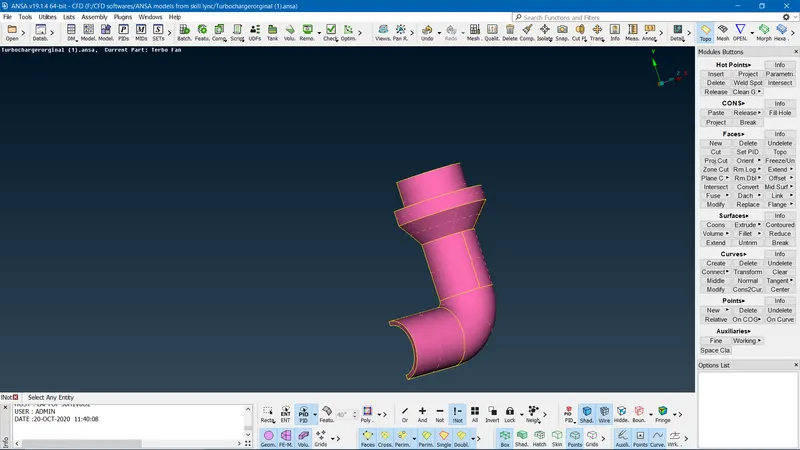
- There is an alternative way too which prevents the time consumption of deleting each and every part instead of using entity(ENT) select the PID option==> select the entire pink surface==> to use the delete option to delete the unwanted surfaces.
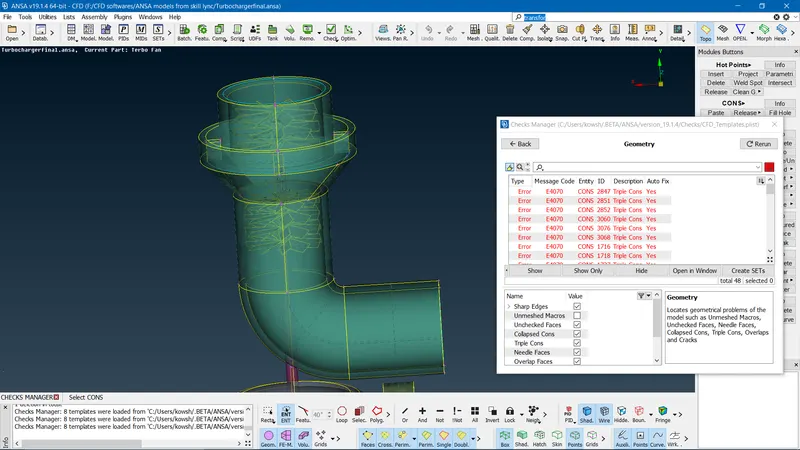
- Once the surface overlapping is taken care we check for errors by using the CHECK option ==>Inside the GEOMETRY window click on execute to check out for errors and get the model to be as shown below.
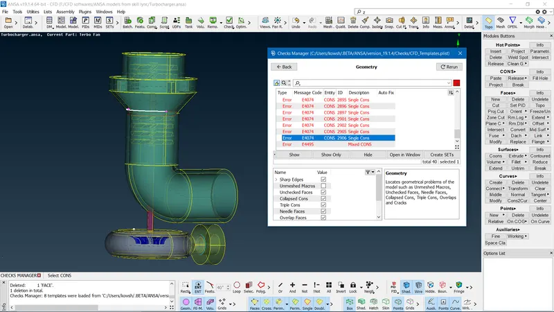
- Since there are some single cons on compressor casing and opening as shown below.
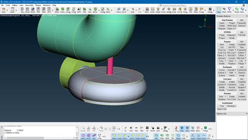
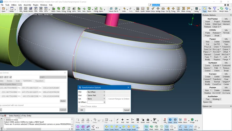
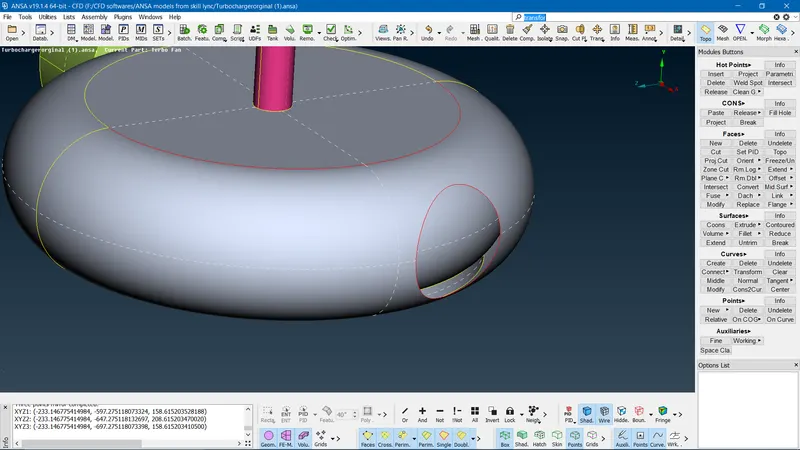
- we can take care of the above problem by a mirror of one part of the casing onto another. The following steps are to create the HOT POINTS on single cons By using the INSERT option. once this is done search for TRANSFORM(COPY ENTITIES option)==>select mirror 3 point plane==>select 3 hot points==>we get TRANSFORMATION option==>ok. To fill the empty hole we use the FILL HOLE option==>select the single cons ==>ok as shown below.
- Next geometrical errors are intersections between the blade stage and shaft rotor, and Impeller and shaft rotor. The first part of this error is due overlapping surface of both the blade stage and shaft rotor and the Impeller and shaft rotor. This is rectified by deleting the unwanted surfaces between them. By doing on some parts of rotor shaft we get single cons this can be rectified by using TOPO option.
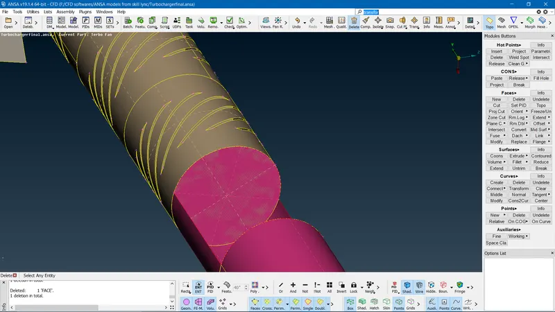
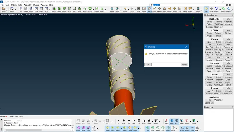
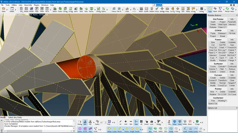
- There is some entity that is difficult to delete on the rotor shaft. This can be rectified by using the PROJECT option to project the single cons onto the surface and then delete the unwanted entity.
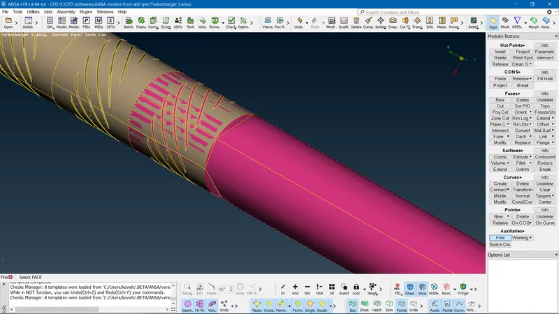
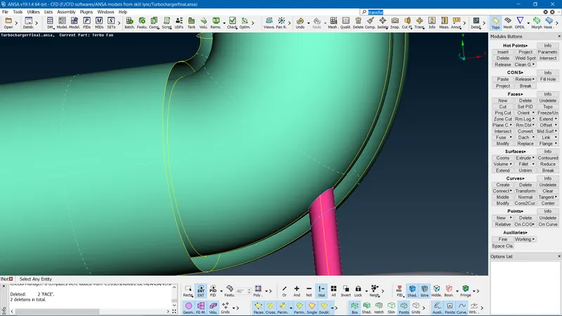
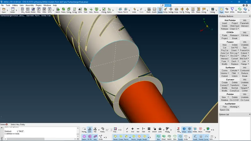
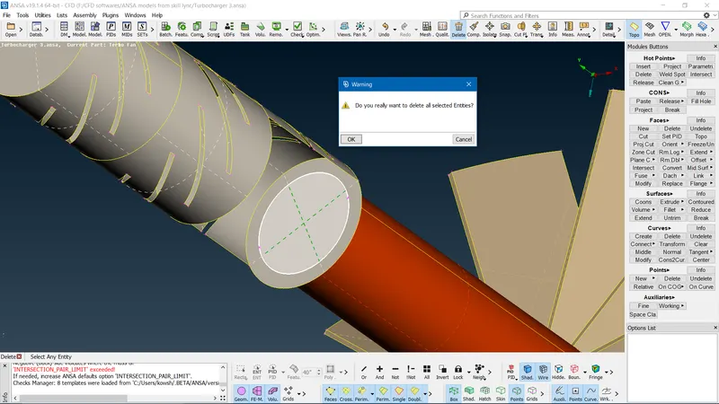
- Next is the TRIPLE CONS error. This cannot be said as an error or these triple cons are valid at a certain point in geometry because the are three surfaces meeting up. But there is an unnecessary triple con error that has to be taken care of by using the DELETE option to delete the unwanted surface as shown below.
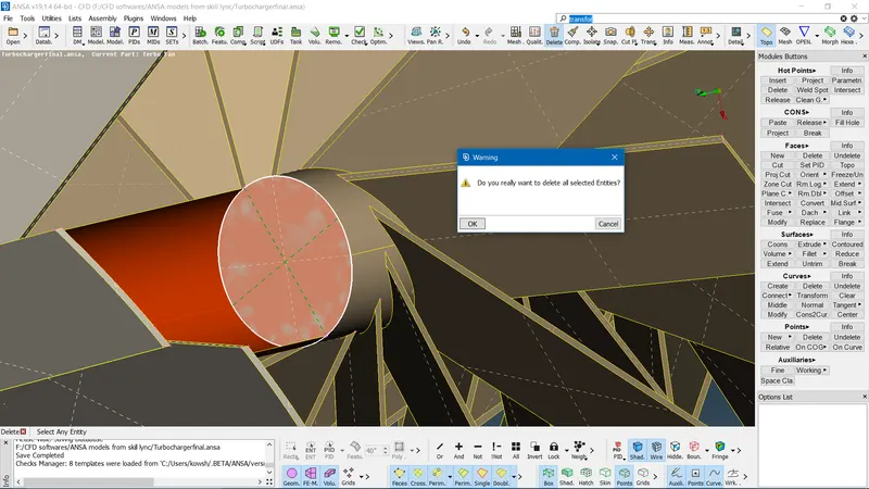
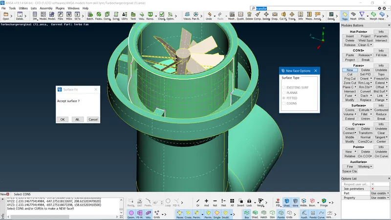
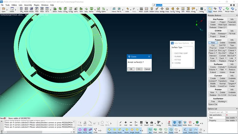
- The next step is to take care of left-out geometry such as single cons. By using FACE(NEW option)==>select FITTED ==> select the single cons==>ok.
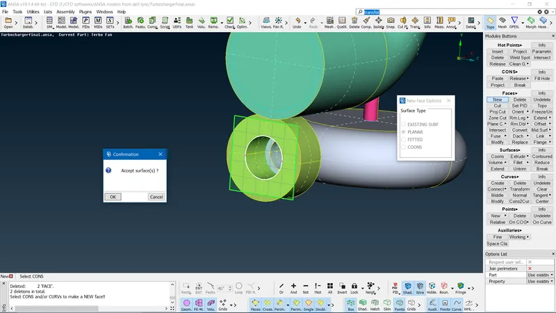
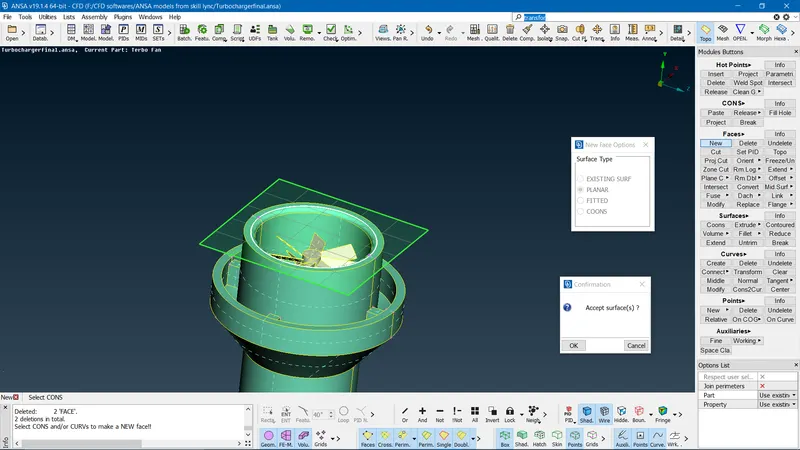
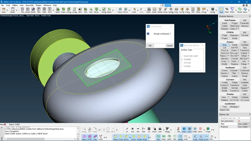
- In order to perform analysis, we need to create airtight geometry by closing the inlet surfaces of the Compressor casing, Inlet casing cover, Inlet, and outlet of the Turbo casing. This is done by creating a new surface by using the FACE option==> select PLANNAR option==> select the double cons==>ok(as shown below).
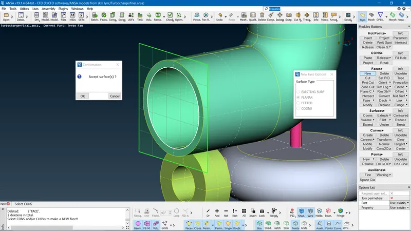
- As shown below this is a valid triple con error because there are three surfaces meeting up in the geometry. Hence these errors can be ignored and procced for the MESHING process.
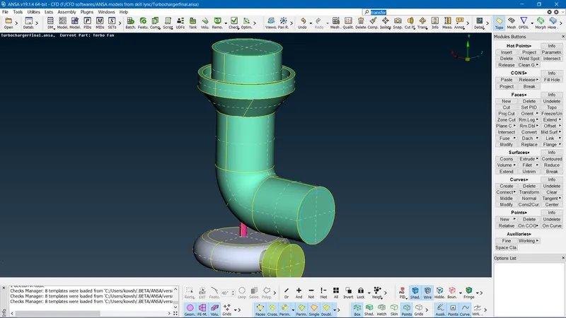
- Once geometrical errors are taken care we get the turbocharger as shown below.
STEP1-SURFACE MESHING
- Once the model is taken care of geometrical errors, now it's ready for the meshing process. For meshing, we cannot select the entire model and mesh because as part of the challenge each component(PIDs) is given a different target as per PID.
- First, we select the impeller component hide all other PIDs.
- Under PERIMETER option==>select LENGTH==>we get selection windows (PERIMETER AND MACROS)==>first select PERIMETER select entire pressure value or individual PIDS select ok/middle mouse click==>In next window give target length as 2mm==>ok.
- Similarly select MACROS select entire pressure value or individual PIDS select ok/middle mouse click==>In next window give target length as 2mm==>ok/middle mouse click.
- Under MESH PARAMETERS give the target length as 2mm and element type as TRIA.
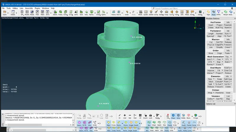
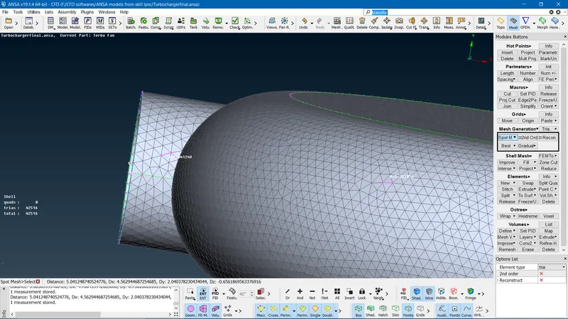
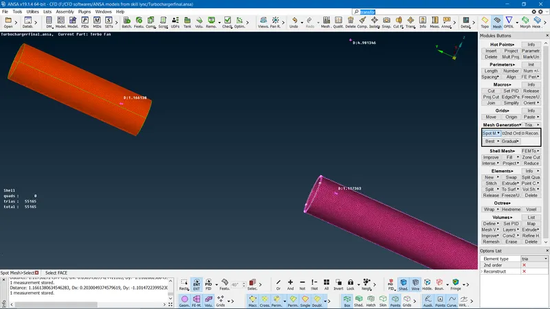
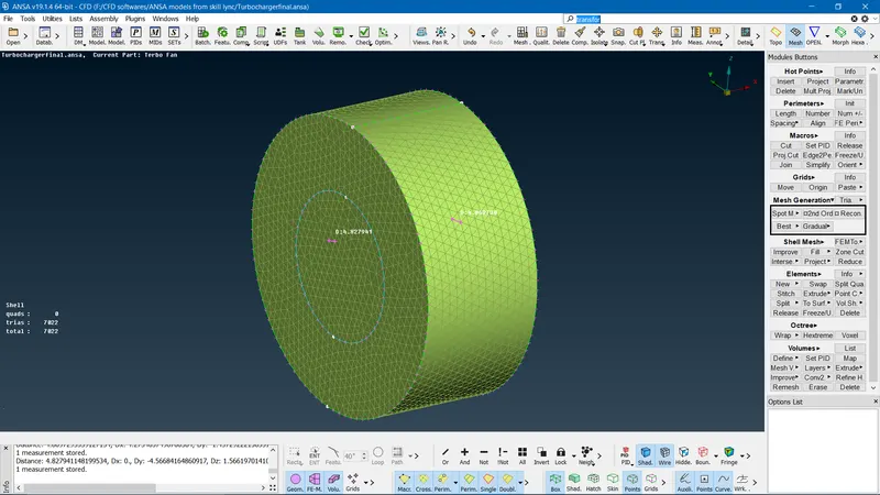
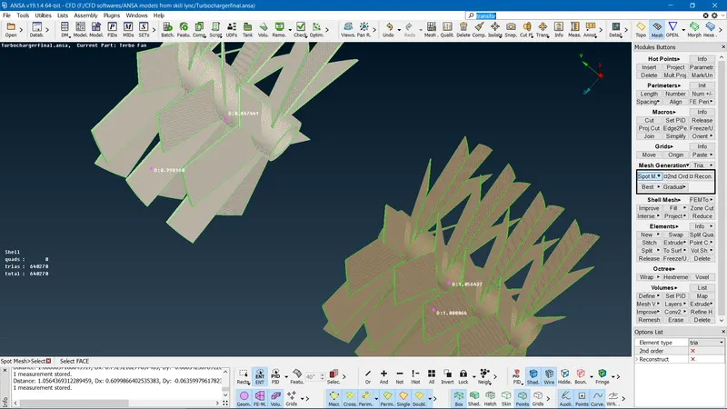
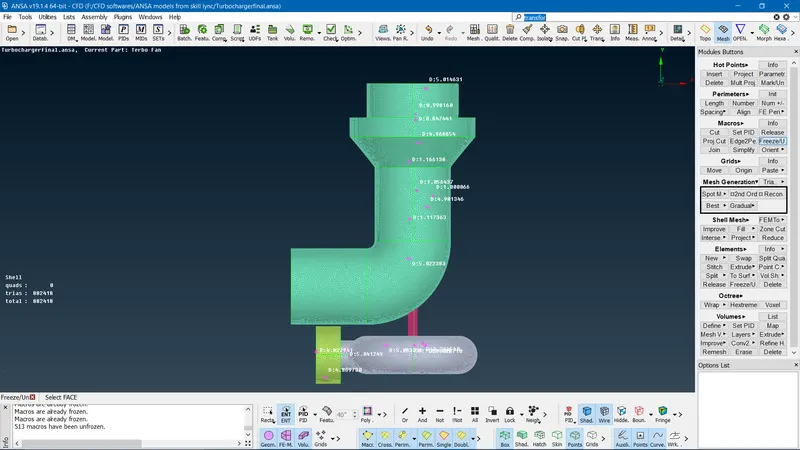
- Lastly under the MESH GENERATION option==> select SPOT MESH option==> select entire pressure value or individual PIDS. Finally, we get the meshed pressure valve(the MEASURE option is used to check the distance between two node points on the meshed pressure valve surface) as shown below.
- Lastly UNFREEZE option is used on PIDs so that once the surface has meshed in order to keep the component from any other changes we use this option.
- The above steps are repeated for each and every PID but the only difference is when we are changing the target lengths based on provided data.
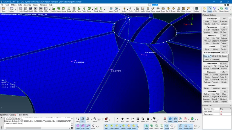
- Finally, we use UNFREEZE option for all the PIDs by right click drag and selecting all the components, and then assembling it as shown below.
STEP 2 VOLUME MESHING
- To study the fluid flow analysis inside the turbocharger we need to perform the volumetric meshing to understand the fluid behavior on the inside surface of the turbocharger.
- First, we change from the MESH option to the V(VOLUME) MESH option.
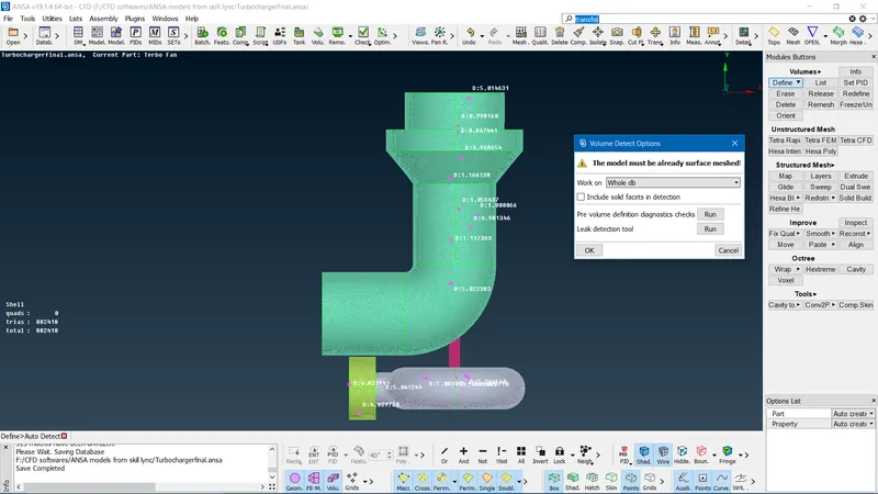
- We have to define the volume by selecting the DEFINE option under volume==>change to WHOLE DB==>ok.
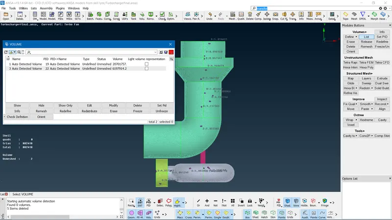
- Next step we get a LIST of volumes which is auto-detected and presented. Check for the required volume for performing volume meshing and delete the rest of the volumes.
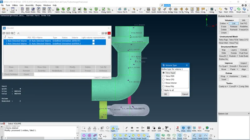
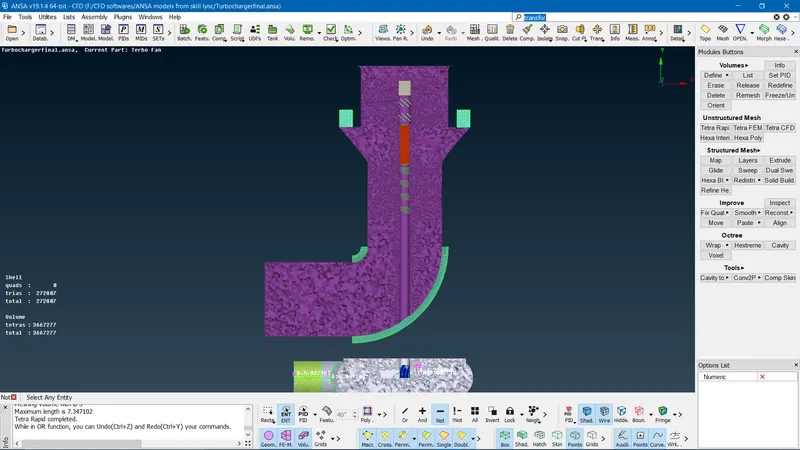
- Under the UNSTRUCTURED mesh, option ==>select TETRA RAPID option (to define the type of mesh)==>ok.
THE FINAL VOLUME MESHED SURFACE IS SHOWN BELOW
LINK FOR TURBOCHARGER MODEL
https://drive.google.com/file/d/1fsRfd3eoVr6kZqubqlEn_t8IXaIBshid/view?usp=sharing
CONCLUSION:
I have successfully meshed the turbocharger(surface mesh and volumetric mesh) based on different component target lengths and for element type TRIA. Also, we can see that for different element sizes we get smooth mesh for the surface. For volumetric we see there is a mixed type of mesh in the mid portion(due to the presence of blades 1 and 2) of turbo casing rest of the volume is unstructured mesh. Also, we can find this mixed type of mesh in the compressor casing due to the presence of an impeller.