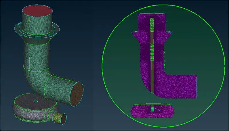
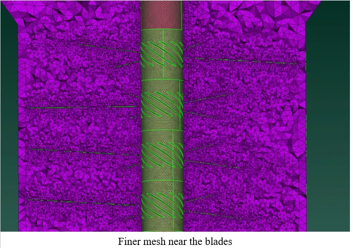
Week 3 Challenge : CFD meshing on Turbocharger
Aim:
- The goal here is to refine the geometry and perform surface and volume mesh.
Take Away:
By the end of this article you will be familier with,
- Exploring different option to refine the geometry (fill hole, new faces, creating hot points etc).
- Meshing each component individually for refined and mesh where ever necessary.
==============================================================================
INITIAL GEOMETRY:
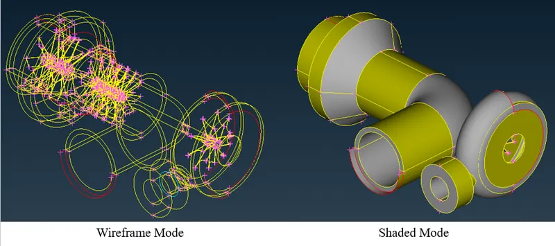
Errors in the Geometry:
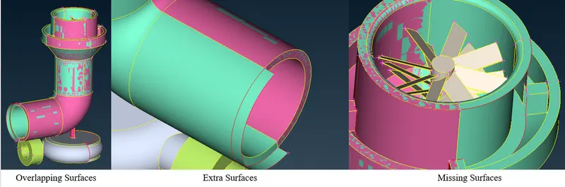
- The above figure shows what kind of topology clean up is required.
- Whole geometry is filled with these kind of errors and we will be discussing the rectification of these errors.
==============================================================================
TOPOLOGY CLEAN UP:
- The very first step is to do a GEOMETRY CHECK.
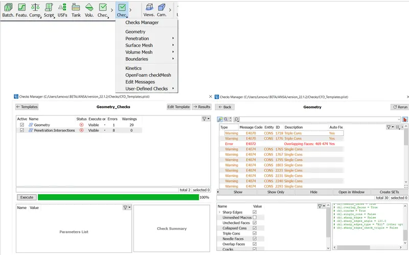
- Clicking on each of the errors, one can see in the GUI where is the error actually located.
- It is better to clean the geometry part by part.
- Once the geometry is ready for meshing, we will be setting PIDs for better model control while meshing.
Essential Tools:
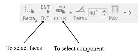
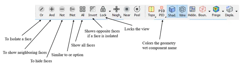
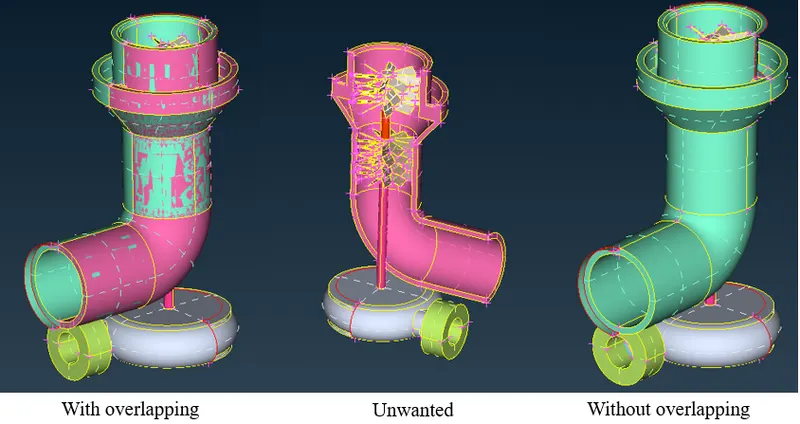
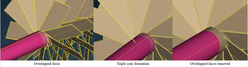
----> Exploring removal of Overlapping faces:
- Hide the green surface.
- Make sure you are in PID mode.
- After hiding the green face, you will be left with pink faces which is not necessary.
- Delete the face.
----> Exploring the FILL HOLE option:
- Here, first the entire edge is removed.
- Then the void is filled with the help of FILL HOLE option.
- Delete the face.
- Select FILL HOLE option, select bounding cons to fill the gap. (TOPO --> FACES --> FILL HOLE).

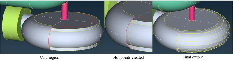
----> Exploring the INSERT HOT POINTS and then create faces:
- In this particulaer scenario, FILL HOLE will not work. Take a peek below:
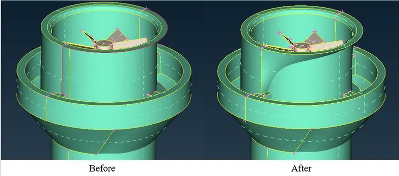
- As seen this does not work.
- So, the alternative is to create HOT POINTS using existing HOT points.
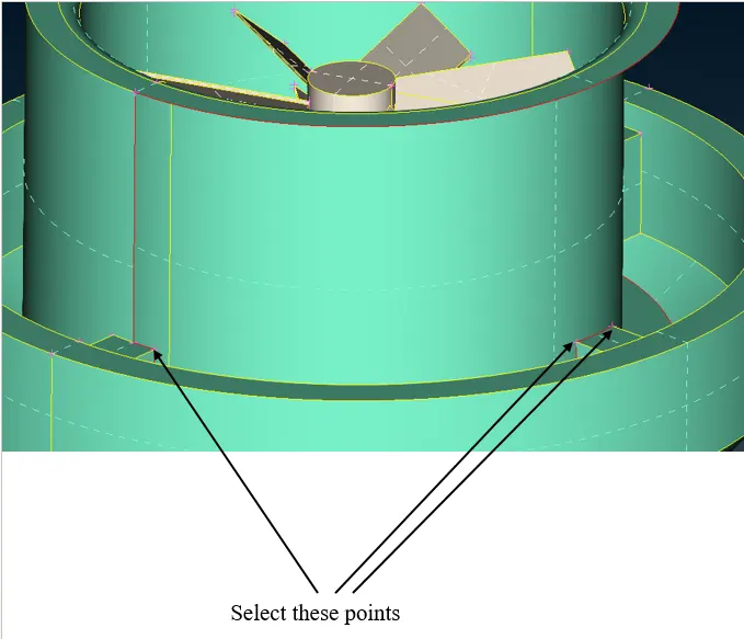
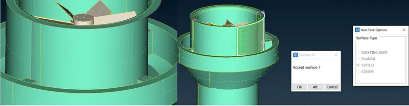
- After selecting the points, project onto the upper cons.
- Select PROJECT option. (TOPO --> HOT POINTS --> MULTI PROJECT)
----> Exploring the INTERSECT option:
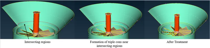
- This option is used to make intersection between two surfaces and form a triple con for furthur removal of the face.
- Select INTERSECT option. (TOPO --> FACES --> INTERSECT).
- It asks you for two sets of faces, select the faces that intersect.
- Then delete the unwanted region.
----> Exploring the PARAMETRICAL option:
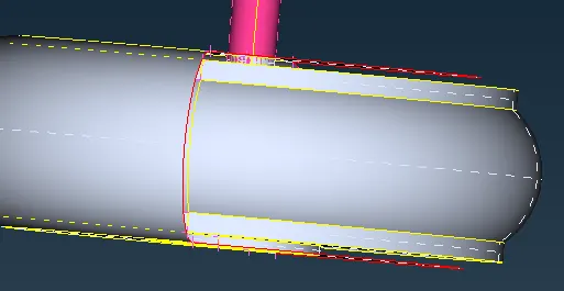
- This is used to create hot points on a existing cons.
- Select PARAMETRICAL option. (TOPO --> HOT POINTS --> PARAMETRICAL)
- It asks you to specify the distance as it assumes the distance is 1 mm. (kind of percentage of actual distance)
- This tool will be used to cover the following region:
- Final output,
----> Exploring the CONS PROJECT option:
- This tool is used to project the cons on to other face to seperate the faces.
- Select PROJECT option. (TOPO --> CONS --> PROJECT)
- It asks you to select set of edges/cons to be projected and later asks you to select the face on which the edges/cons are supposed to be projected on.
==============================================================================
Setting up the PIDs:
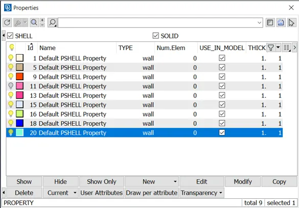
- Select the PID option present in ribbon.
- A window will pop up with pre assigned names.
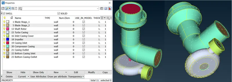
- One must assign proper names for better identification.
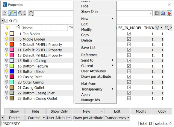
- Right click on the pre defined PIDs and select APPLY option.
- Next step is to select the face/component.
==============================================================================
Meshing the Geometry:
- There are regions where mesh has to be finner for better capturing of physics and there are regions where physics is not much of an importance.
- So, each of the component/PIDs are meshed individually for variable mesh element size.
- To mesh the component individually, only the PIDs of interest should be visible, rest must be hidden.
- This way we can work our way out to mesh the individual components.
- Below is the chart of different element size for different PIDs:
- Blade stage-1 = 1 mm
- Blade stage-2 = 1 mm
- Impeller = 2 mm
- Shaft rotor = 1 mm
- Turbo casing = 5 mm
- Compressor casing = 5 mm
- Inlet casing cover = 5 mm
- Starting with the make sure you are in Mesh deck.
Meshing Compressor Casing:
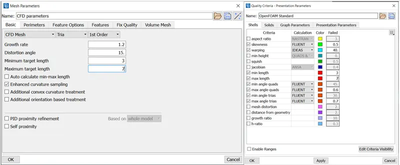
- Target Length = 5 mm
- Minimum Length = 3 mm
- Maximum Length = 7 mm
- The above values must be specified in MESH PARAMETERS AND QUALITY CRITERIA.
- Select the LENGHT option. (MESH --> PERIMETERS --> LENGTH)
- Give element size of 5 mm in PERIMETERS and MACROS.
- After assigning, select SPOT MESH option. (MESH --> MESH GENERATION --> SPOT MESH)
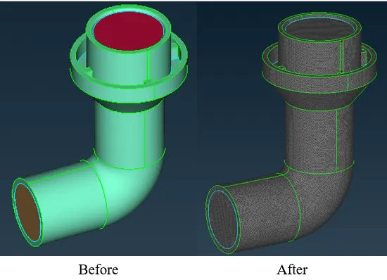
Meshing Turbo Casing and Inlet Casing Cover:
- Target Length = 5 mm
- Minimum Length = 3 mm
- Maximum Length = 7 mm
- The above values must be specified in MESH PARAMETERS AND QUALITY CRITERIA.
- Select the LENGHT option. (MESH --> PERIMETERS --> LENGTH)
- Give element size of 5 mm in PERIMETERS and MACROS.
- After assigning, select SPOT MESH option. (MESH --> MESH GENERATION --> SPOT MESH)
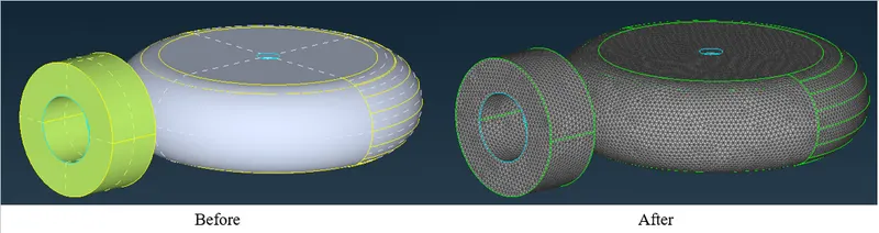
Meshing Blade Stage_1, Blade Stage_2 and Shaft Rotor:
- Target Length = 1 mm
- Minimum Length = 0.5 mm
- Maximum Length = 2 mm
- The above values must be specified in MESH PARAMETERS AND QUALITY CRITERIA.
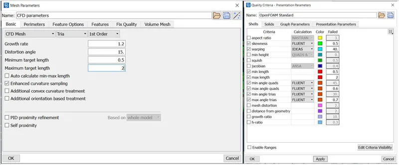
- Select the LENGHT option. (MESH --> PERIMETERS --> LENGTH)
- Give element size of 1 mm in PERIMETERS and MACROS.
- After assigning, select SPOT MESH option. (MESH --> MESH GENERATION --> SPOT MESH)
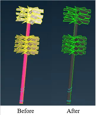
Meshing Impeller:
- Target Length = 2 mm
- Minimum Length = 1 mm
- Maximum Length = 3 mm
- The above values must be specified in MESH PARAMETERS AND QUALITY CRITERIA.
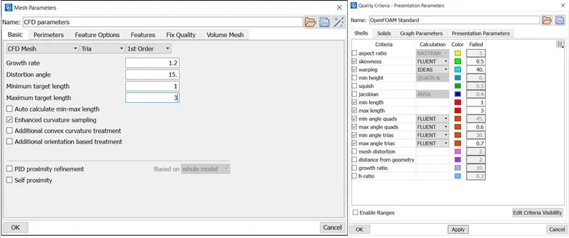
- Select the LENGHT option. (MESH --> PERIMETERS --> LENGTH)
- Give element size of 2 mm in PERIMETERS and MACROS.
- After assigning, select SPOT MESH option. (MESH --> MESH GENERATION --> SPOT MESH)
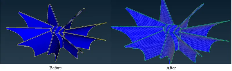
- Sometimes there might be some instances where the face junction (ie shared edge) have different mesh length size.
- Therefore, it will not mesh few faces. Look out for the figure below:
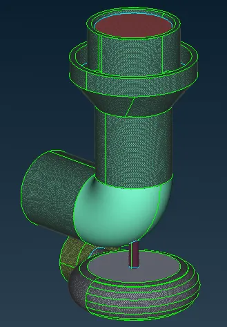
- This can be rectified by selecting the edges of the respective ummeshed PIDs.
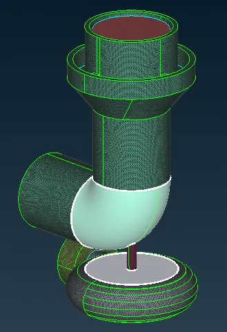
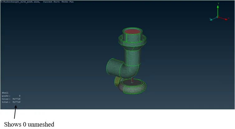
- Finally done with the surface meshing.
- This can be known by seeing at the side of the viewport.
- Now we can proceed with volume meshing.
- Select DEFINE option. (MESH --> VOLUME -->DEFINE).
- Pop up window will ask you for the whole database to mesh. Select ok.
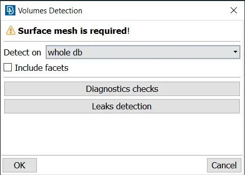
- ANSA will auto detect the voids in the geometry and try will try to fill it.
- Some of the volume generated is not required as the fluid is not going to flow through it.
- Therefore, we must delete those generated volumes.
- Assurity can be done by selecting the paramater and looking at the preview.
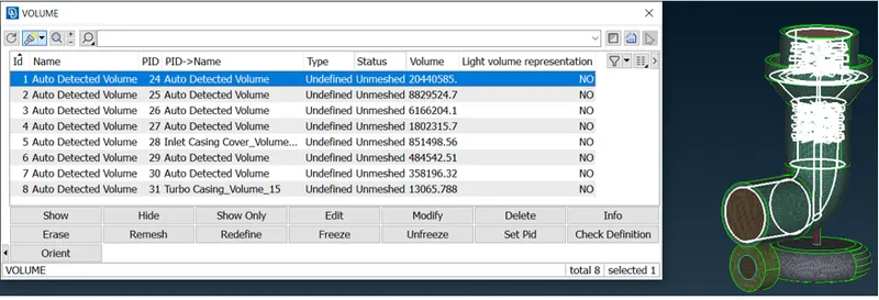
- After deleting the unwanted volume mesh, ANSA has still not mesh the required volume.
- Inorder to do that we have to remesh the entire left over domain.
- One has to choose tetra CFD option while meshing.
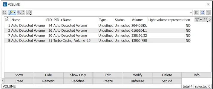
- Remesh the domains, by right clicking on undefined (see in fig) and select tetra CFD.
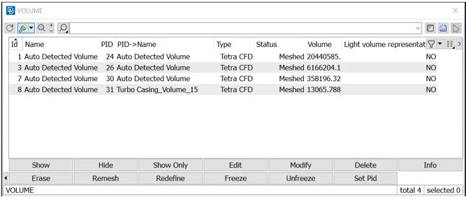
- After meshing the entire domain, the same window (above) should look like this:
Output: