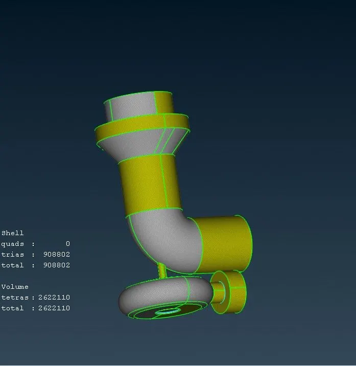
Week 3 Challenge : CFD meshing on Turbocharger
Geometry
The given geometry had many overlapping surfaces ,single cones and triple cones
So before doing the surface meshing or volumetric meshing , the geometry should be free of errors
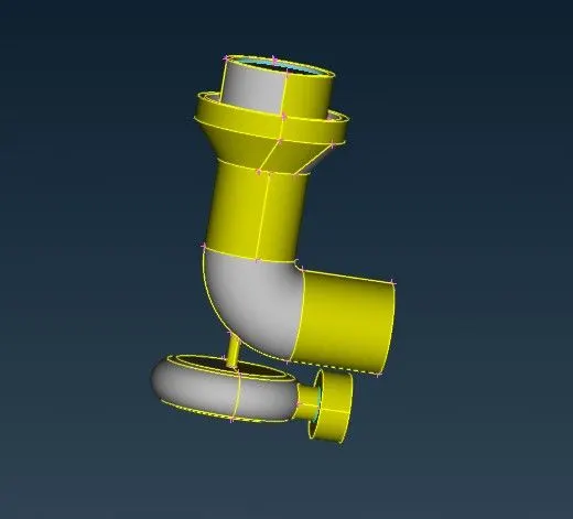
So as a step by step process ,first was to look for single cones ,which appeared in so many areas
mostly the cones where projected to the required surface ,to establish a complete surface or face
Next the overlapping surfaces were deleted
Also the check was done for triple cones and intersecting surfaces
That was also cleared
Surface Meshing
All the check for geometry and interscetions have been done
Blade stage-1 = 1 mm
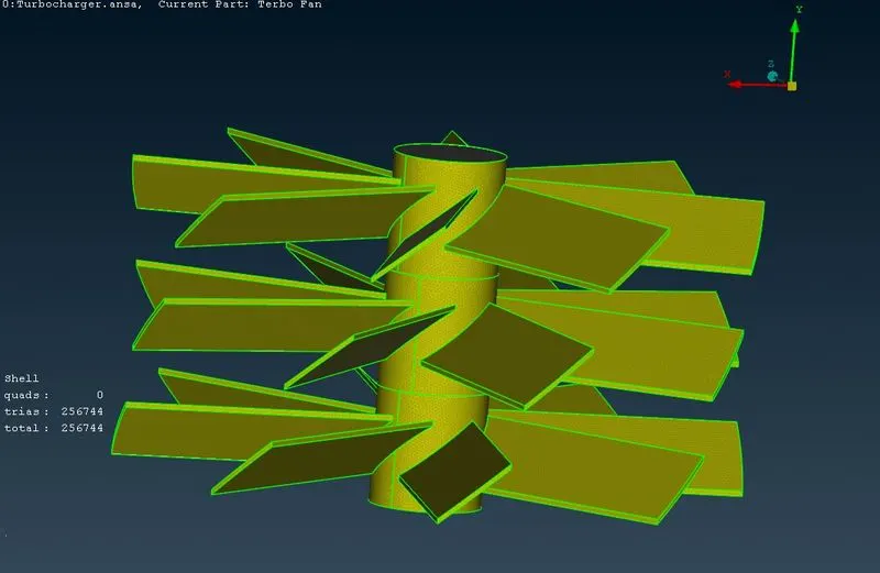
Blade stage-2 = 1 mm
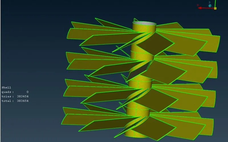
Impeller = 2 mm
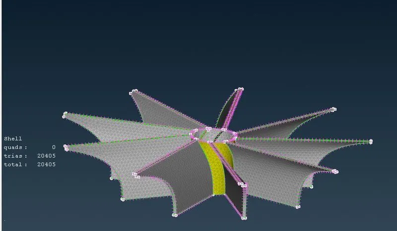
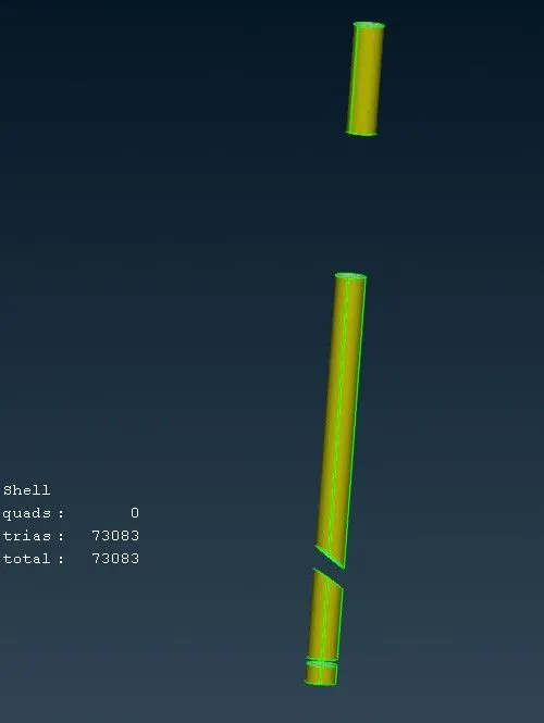
Shaft rotor = 1 mm
Turbo casing = 5 mm
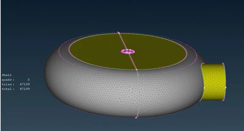
Compressor casing = 5 mm
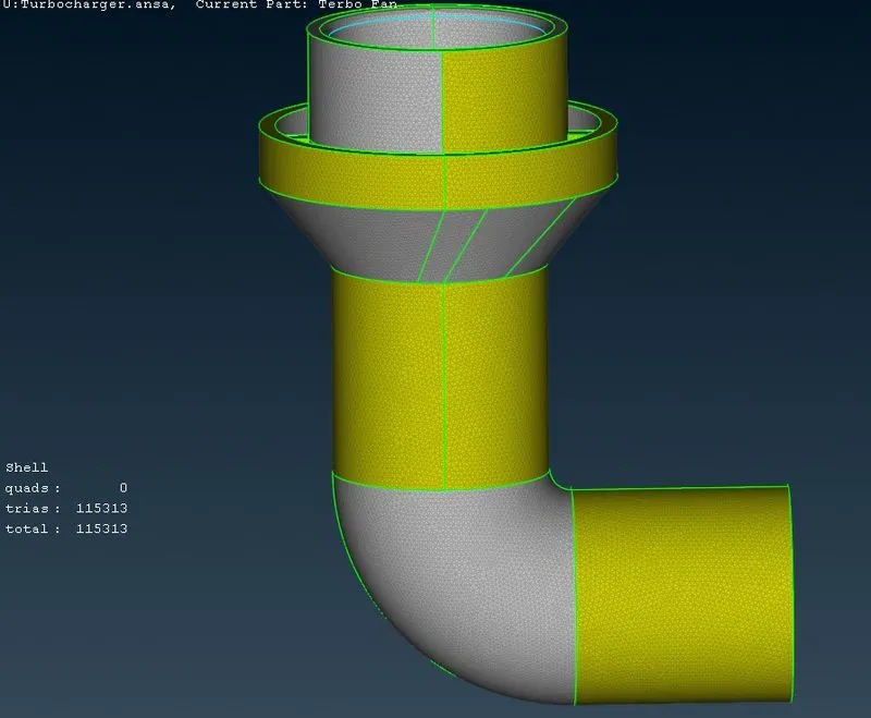
Inlet casing cover = 5 mm
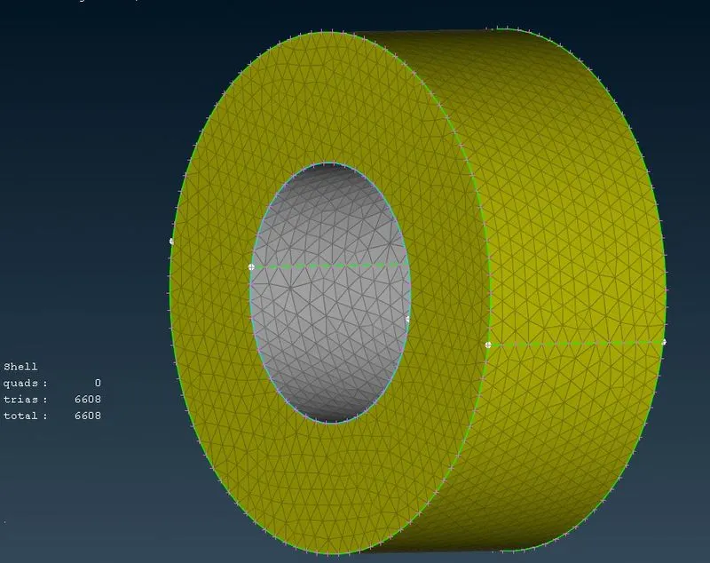
According to the given data the meshing was done for each part of components
For each meshing the quality criteria and meshing parameters are defined
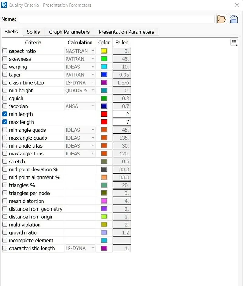
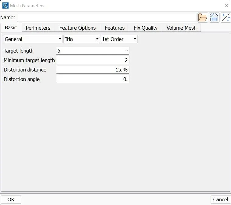
Fo each mesh length the min and max length is defined
Also make sure the tria elements are selected
then using spot mesh the meshing is done
Volume meshing
The surface meshing is done as a prerequisite for volume meshing
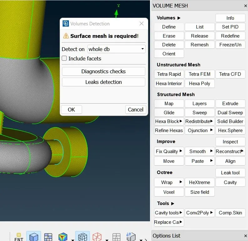
when we click the icon Define under Volumes , volume detections will pop up
Using this we can obtain the list of unmeshed volume
Also The volumes which are not needed can be deleted from this list
Remainig volume is meshed using tetracfd and the geometry is ready for CFD simulation