Week 3 Challenge : CFD meshing on Turbocharger
Goal:
To construct appropriate volumes for the provided model, create and assign PIDs and check for geometrical faults. executing surface mesh in accordance with PIDs using the specified target lengths.
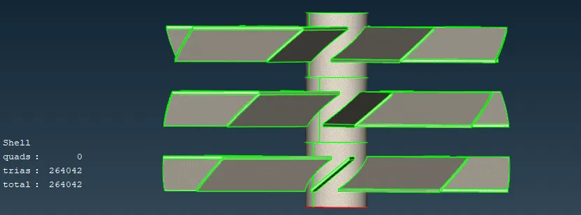
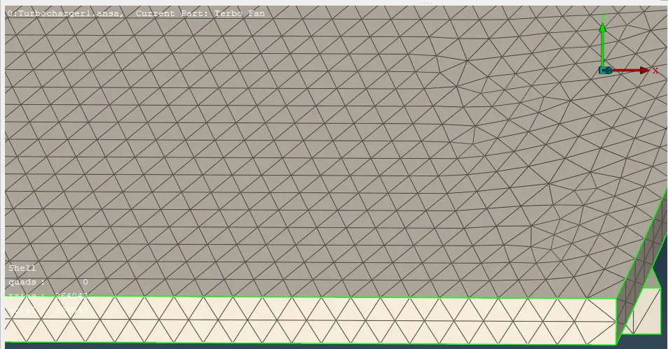
Stage 1 blade = 1 mm
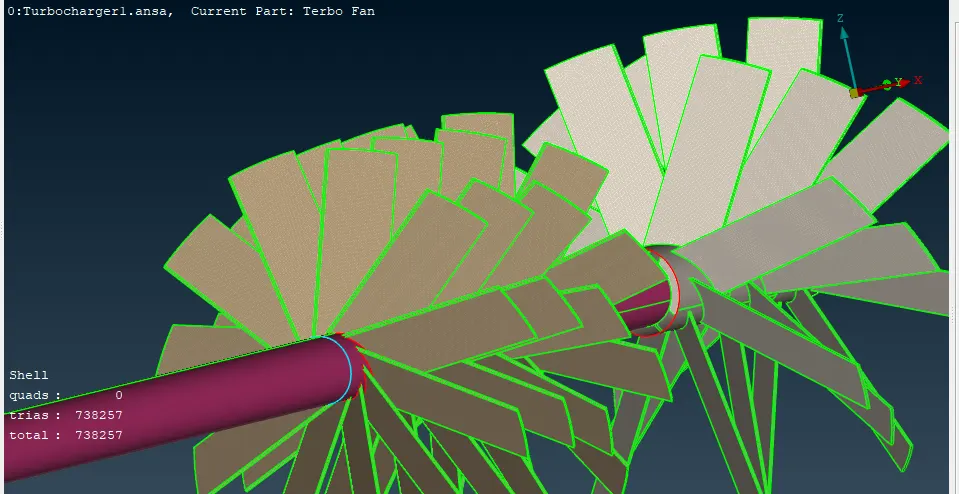
Stage 2 blade = 1 mm
2 mm is the impeller.
1 mm is the shaft rotor.
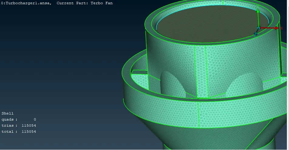
5 mm is the turbo casing.
Compressor case diameter: 5 mm
5 mm is the inlet casing cover.
After that, create a volumetric mesh for the necessary volumes.
DESCRIPTION:
STEP 1)
GEOMETRY CLEAN UP:
Loading the geometry model in ANSA
Here we see a single con, so need to fill it
A proper surface is not getting created
So we need to create small different surfaces by using hot points.
For this we need to project the hotpoints on the other face of this surface
So we have fixed ultimaterly this part but still we see glitchings on the surface. We need to fix this glitchings.
Using 'TOPO tool' to check are there any triple cons
By using the delete too with PID region we see that we are able to delete the glitchings
For the other surface
Creating surface cleanup for another part
so creating hot points using parameters
On the other side creating hotpoints using parameter
Now creating one by one alternate surfaces as follows
Ultimaterly whole surface is created as follows
In the wireframe mode we see still a single con
Seecting first group
Then second group
Now we got the triple con so deleting the single cons
Leaving triple cons we see all the geometry checks are accepted
Now we need to fix the triple cons for all the surfaces
Using the CON project tool, we select the double CON then left click on the required surface to cut the CON and the use fine tool to fine the surface and then delete it. Now its fixed
Executing Geometry check for the above model we see no triple, single cons
Now performing Geometry checkup for the entire model
We discover that there is now only one triple con, which is necessary. It is not an error, even if it appears to be erasing the surfaces it is related to.
Now inspect the geometry for any openings; if not, shift the geometry to execute the volumetric mesh and an error will occur. As a result, we locate no openings.
PID manager is now being assigned the names.
Making sure the component below is free of any other components by checking and examining it, then labelling it OUTSIDE CASING
And now even closing the inlet and outlet as follows
As we are able to see the interior components from top view we need to even close the below chamber
Not this part is fixed
Now closing the below part
Applying now the PIDs
Renaming them
Checking for single cons, we don't see any
Checking triple con
MESHING:
1. Blade stage 1:
2. Blade stage 2 and rotor shaft:
3. Casing:
4. Impeller:
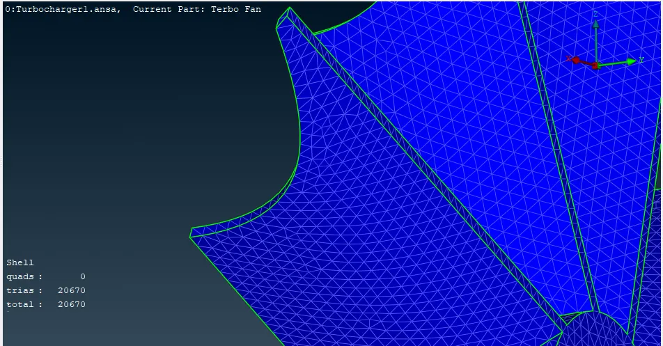
5. Inlet casing cover:
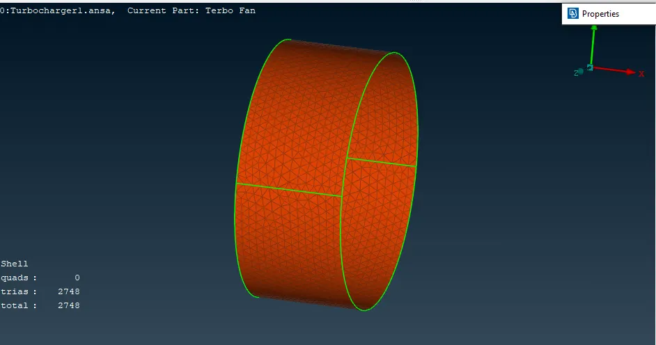
6. Turbo casing:
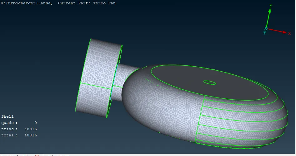
7. Final mesh properties of entire geometry:
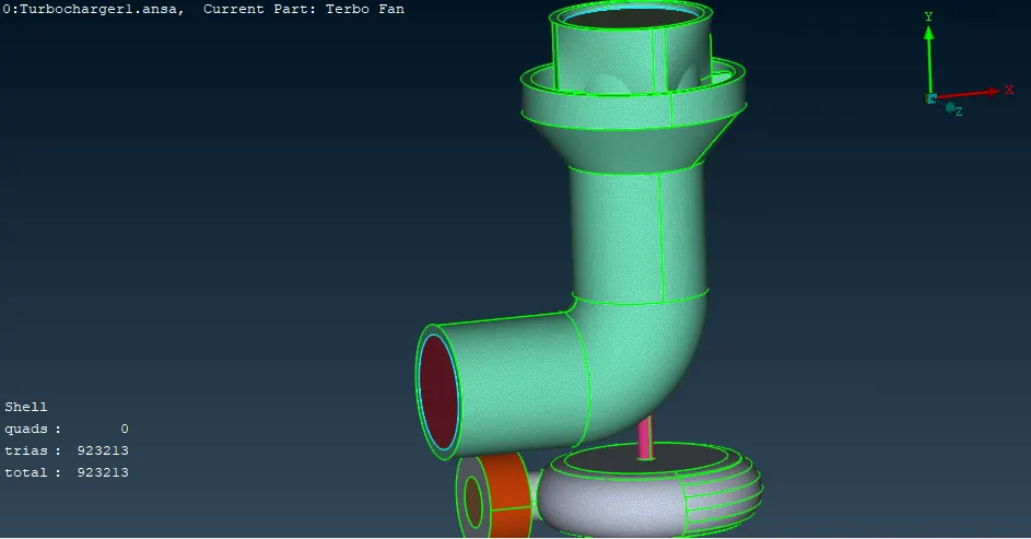
Conclusion:
Thus, the surface is formed for the specified goal lengths, geometrical errors such as single, double, and triple con are checked, and PIDs are allocated in accordance with the need. After that, successful volumetric meshing is carried out for the needed volume.