Week 3 Challenge : CFD meshing on Turbocharger
AIM : To perform CFD meshing on Turbocharger in ANSA.
OBJECTIVES :
- Loading up the Geometry in ANSA.
- To mesh the turbo charger Geometry for the CFD.
- To do the mesh for different stages with different given mesh target lengths - Blade stage-1 = 1 mm, Blade stage-2 = 1 mm, Impeller = 2 mm, Shaft rotor = 1 mm, Turbo casing = 5 mm, Compressor casing = 5 mm, Inlet casing cover = 5 mm
INTRODUCTION :
CFD meshing is a crucial step in Computational Fluid Dynamics (CFD) simulations. It involves applying a numerical grid to a fluid body and its boundary, similar to meshing in finite element simulations. Here are some key points about CFD meshing:
- Meshing Algorithms: These are used to generate collections of grid points. The accuracy of a CFD simulation is determined by these grid points.
- Grid Density: There’s a tradeoff between grid density, solution accuracy, and computation time. Regions with high flow velocity gradient or in boundary layers near curved surfaces may require higher mesh density for better accuracy.
- Mesh Geometry: The mesh points can be connected to define cells that are hexahedra, tetrahedra, or even more complex tessellations.
- Adaptive Meshing: In modern CFD techniques, the mesh density is set dynamically. The density of the mesh follows the physics and structure in the problem, as it depends on the flow gradient and the curvature in the problem.
Different CFD simulation software packages use various algorithms for generating a set of mesh points along the structure to be simulated. The choice of meshing method can significantly impact the efficiency and accuracy of the CFD simulation.
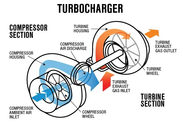
Turbocharger is a device used in an internal combustion engine to increase power output. It uses the energy from exhaust gases to compress intake air, allowing more air into the engine for more power. Unlike a supercharger, which is driven directly by the engine and reduces engine power, a turbocharger uses exhaust gases, so there’s no power loss. Turbochargers are commonly used in diesel engines due to their benefits, but their use in petrol engines is limited. They require good maintenance of engine oil and filters to prevent failures. This device helps improve engine efficiency, reduce weight per horsepower, and maintain power at high altitudes. However, it’s important to note that any dirt in oil and air can cause failures.
STEPS / PROCEDURE :
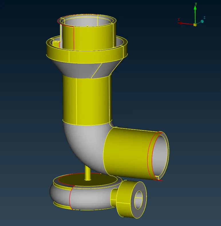
1) Loading Geometry
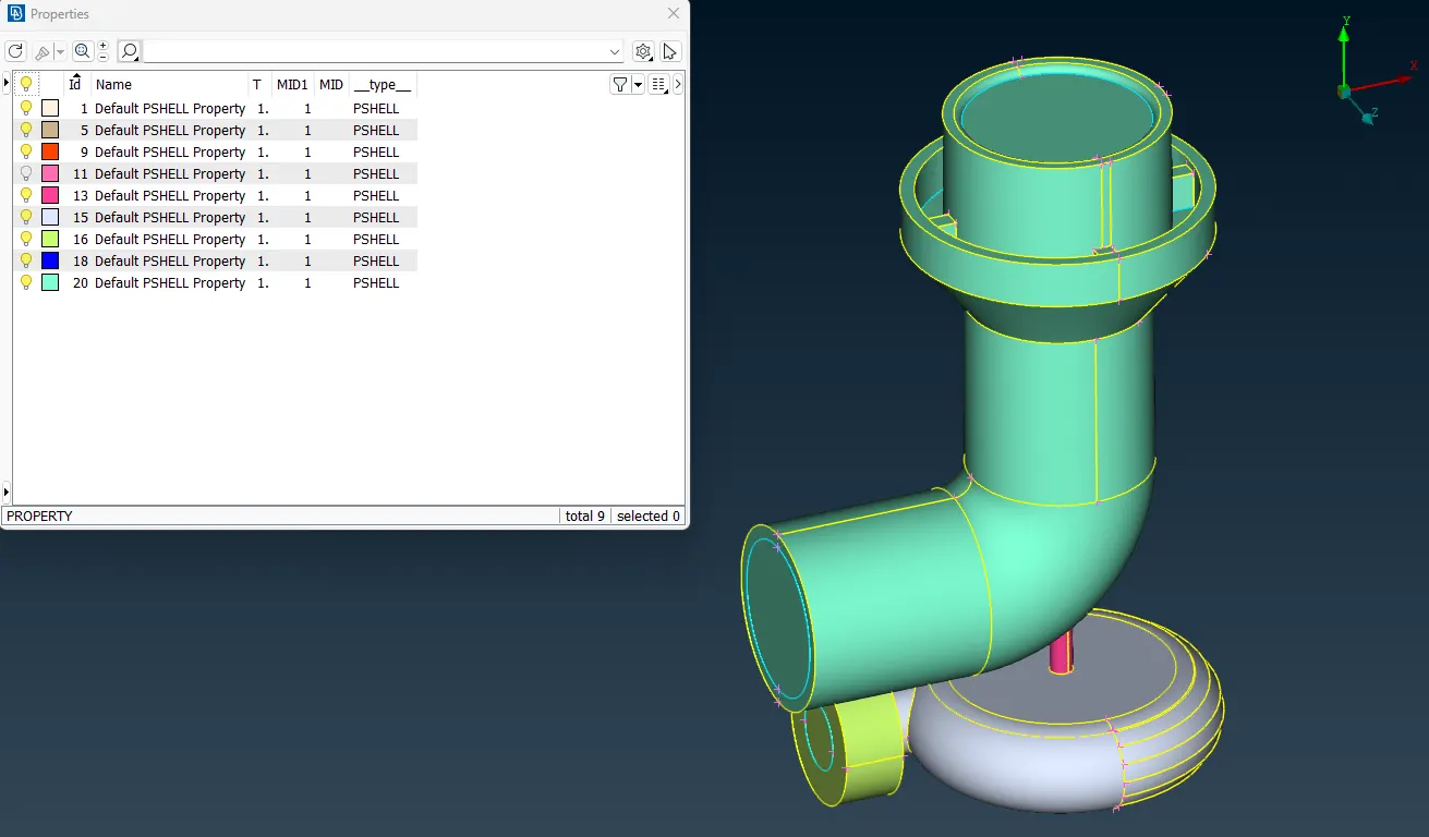
The Following is the geometry given -
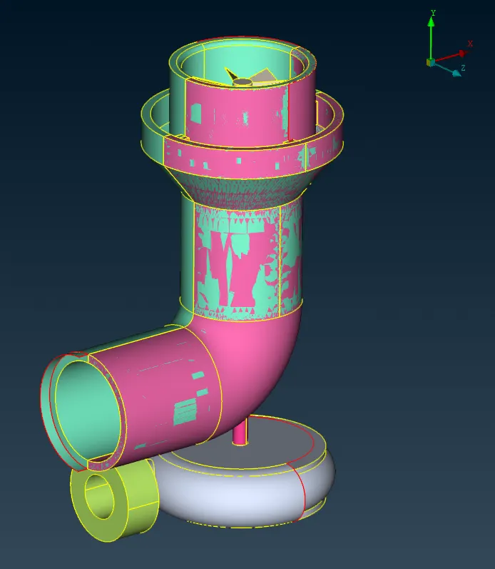
Selecting the PID view -
2) Geometry Cleanup -
Before proceding to meshing we will improve the geometry using tools in TOPO deck.
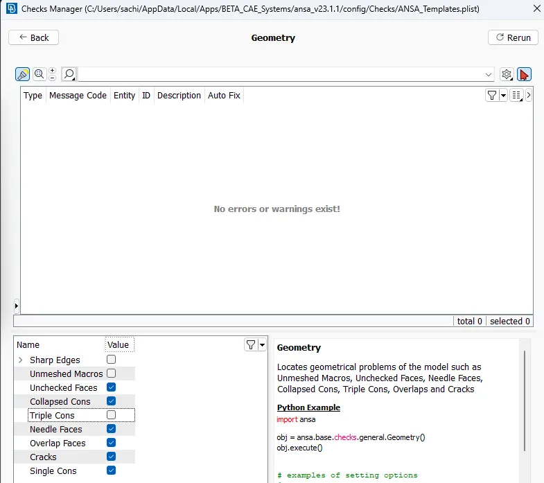
The first thing to do is to check the single cons and triple cons in the model. These are identified using geometric check tool.
As Shown below we got this much singles cons after perfoeming the the gemortric check.
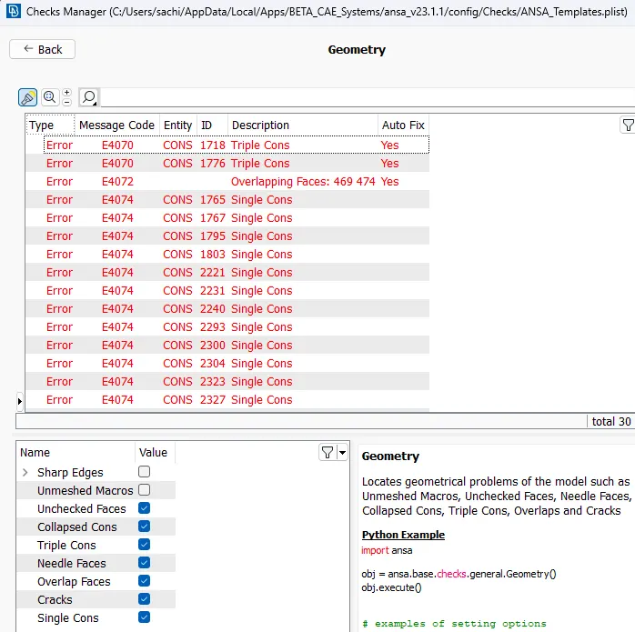
We can see from the Topo check and following image, there are many Single and triplecons and many overapping surfaces.
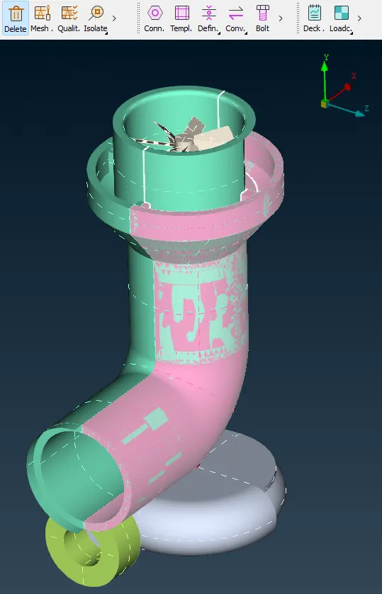
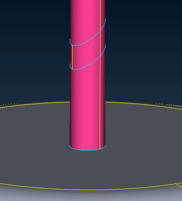
We will complete the cavities by making faces and making single cons to double cons -
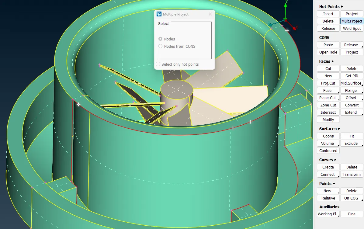
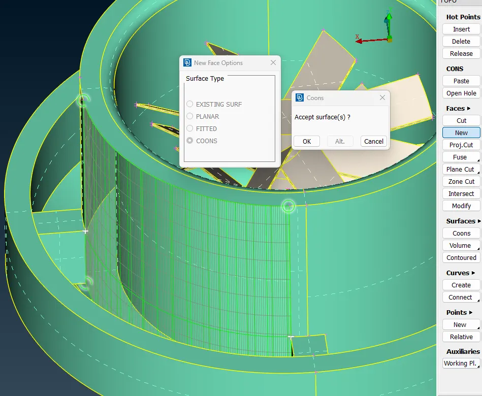
We can use intersect tool inorder to solve overlapped and enlarged surfaces.
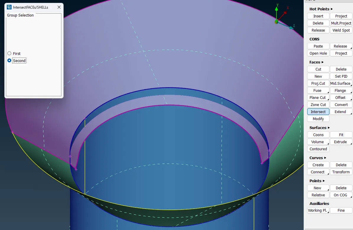
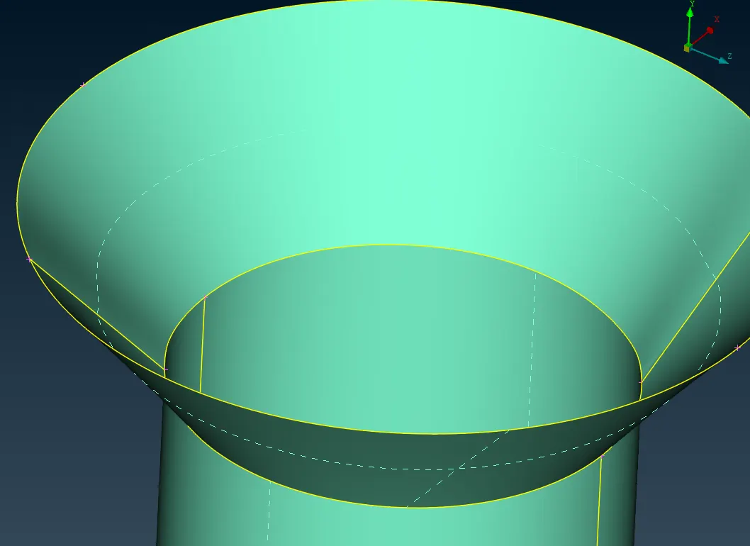
creating sirface to improve missing face by using hot points and face tools.
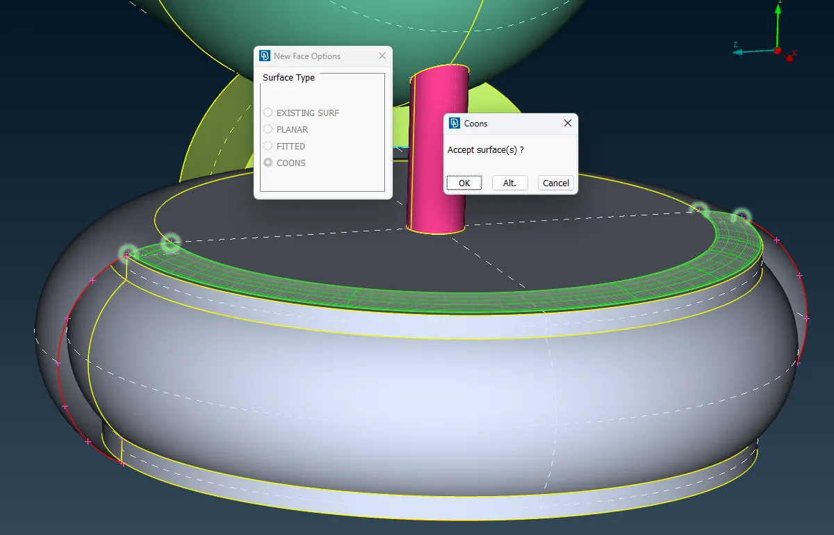
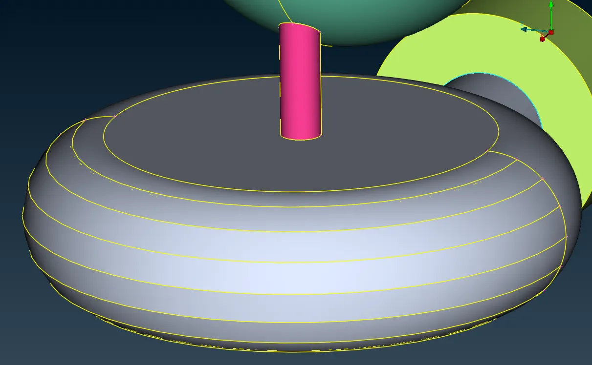
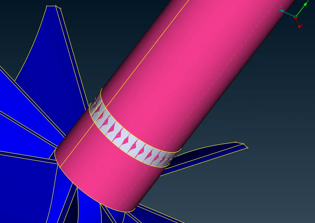
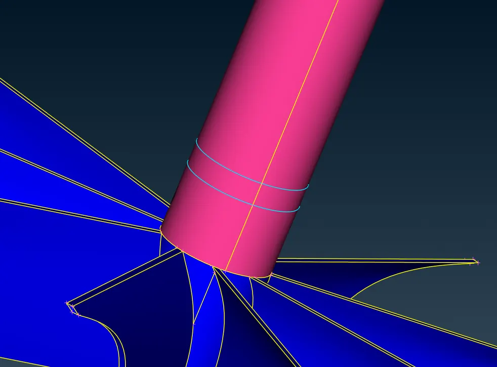
Deleting Overlapped surfaces on the shafts.
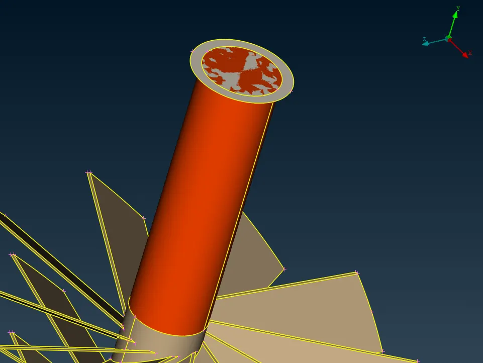
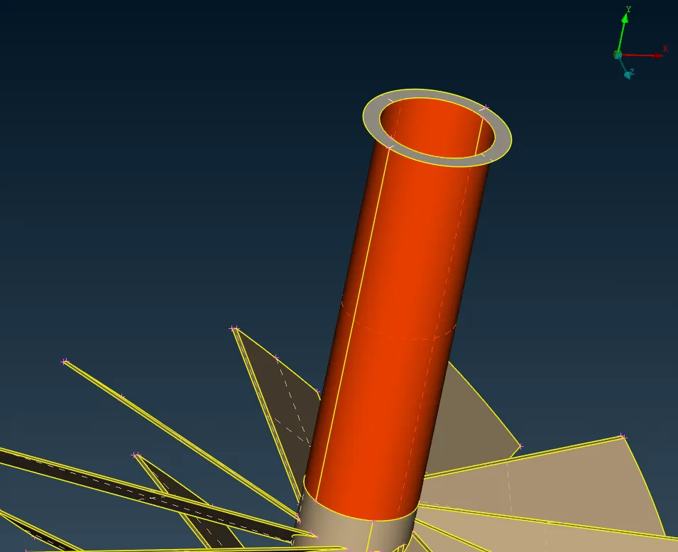
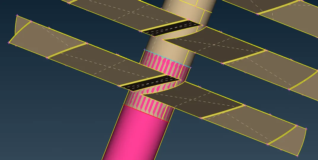
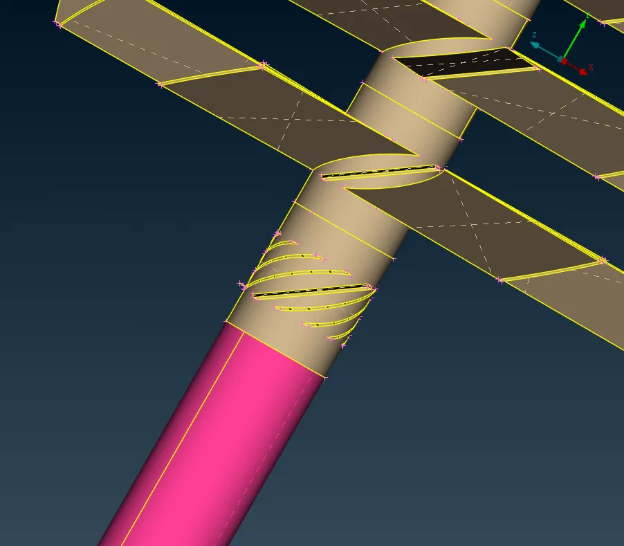
After deleting overlap surfaces the software sometime shows some double cons as single cons or triple cons as single cons. Therefore we topo tool in the topo deck to stitch the surface correctly and updating the cons status.
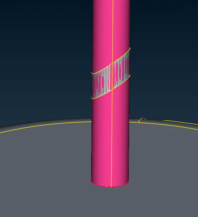
After making TOPO cleanup, using Fill hole tool to create Inlet and Outlet Faces -
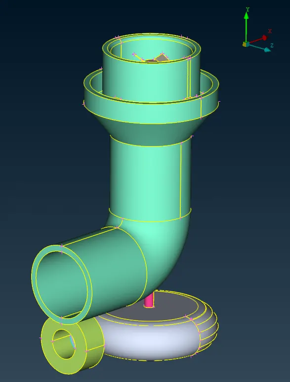
After Completing face creation operaion we again check the topo check.
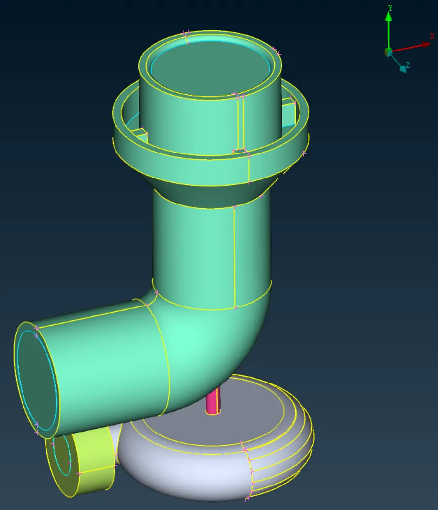
Following is the complete geometry looks like after geometry cleanup-
After completing with the topo cleanup we can assign the PID to the set of surface which designated part of the components
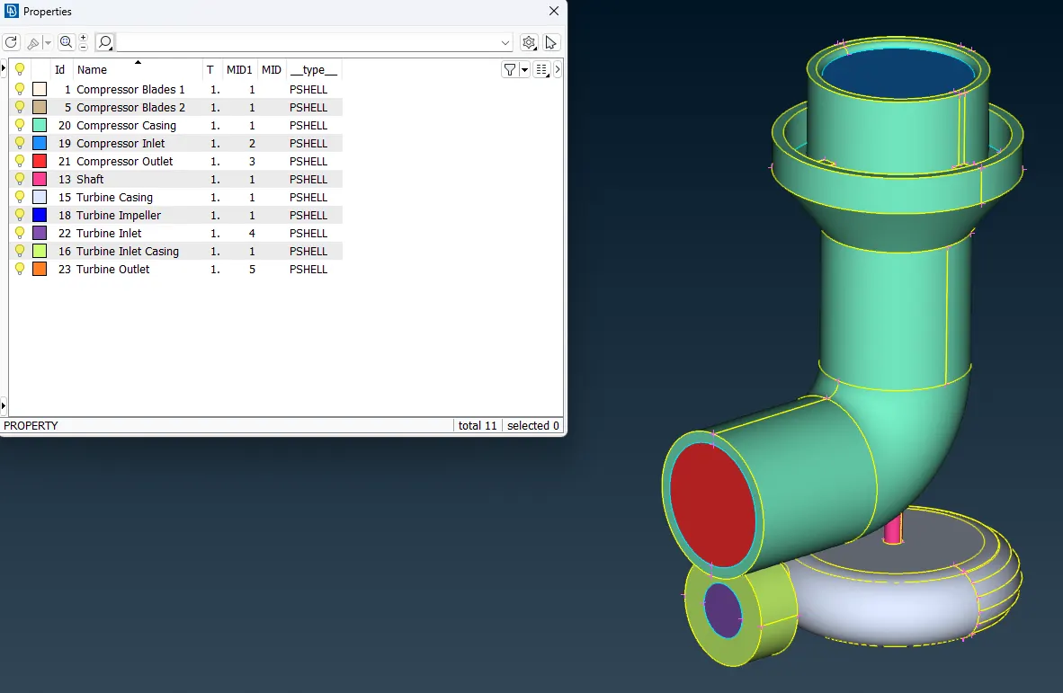
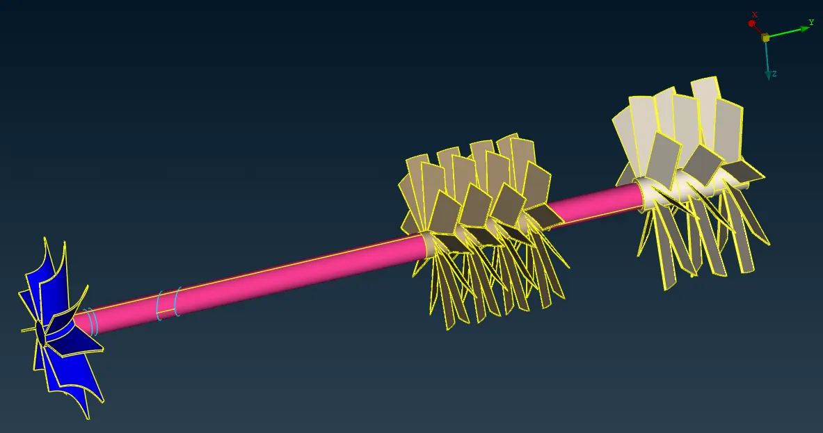
After Completing with the Topo cleanup and PID assignment we move towards the Meshing.
3) Meshing -
From the Classic Mesh deck we can use the length tool inorder to assigning mesh size to the geometry.
Following are the mesh lengths given for the different parts of the turbocharger -
- Blade stage-1 = 1 mm
- Blade stage-2 = 1 mm
- Impeller = 2 mm
- Shaft rotor = 1 mm
- Turbo casing = 5 mm
- Compressor casing = 5 mm
- Inlet casing cover = 5 mm
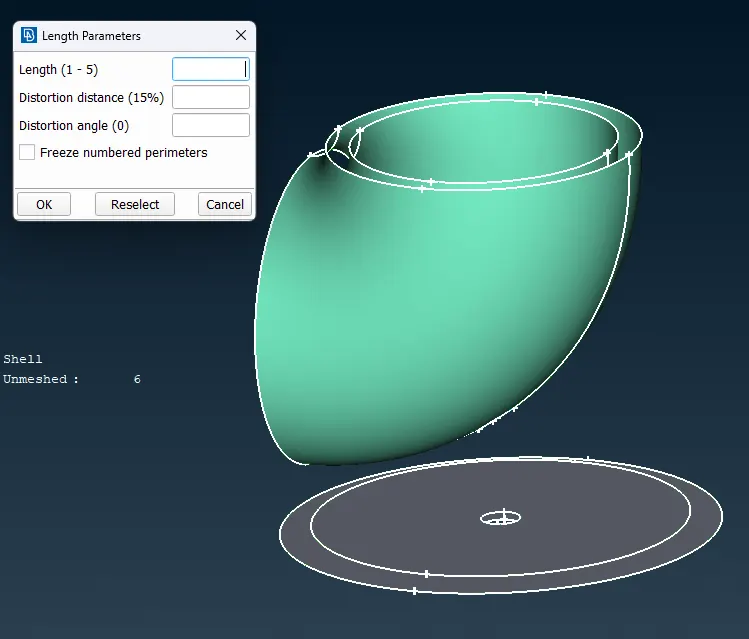
In Length tool, we assigned 5 units size to all faces in both parameters and macros.
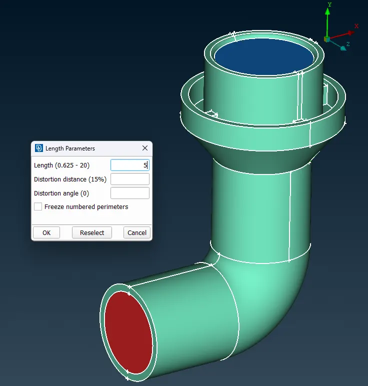
In the Mesh Parameters Section, we will assign 5 units to the target length.
With min and max length criteria be 3 and 7 units respectively.
And setting the Mesh element to Triangle elements.
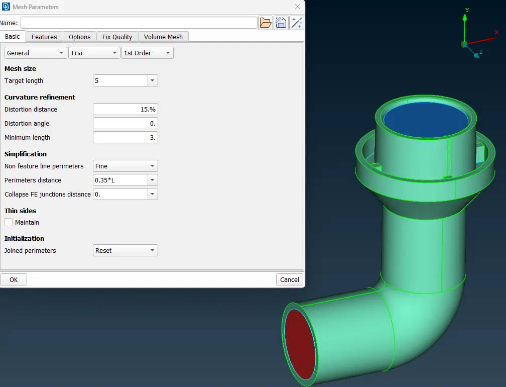
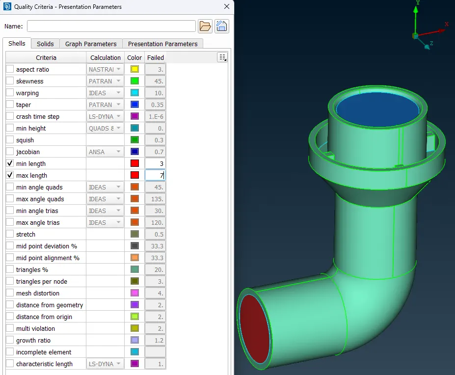
After assigning mesh sizings, we will proceed to generate mesh using Spot meshing tool.
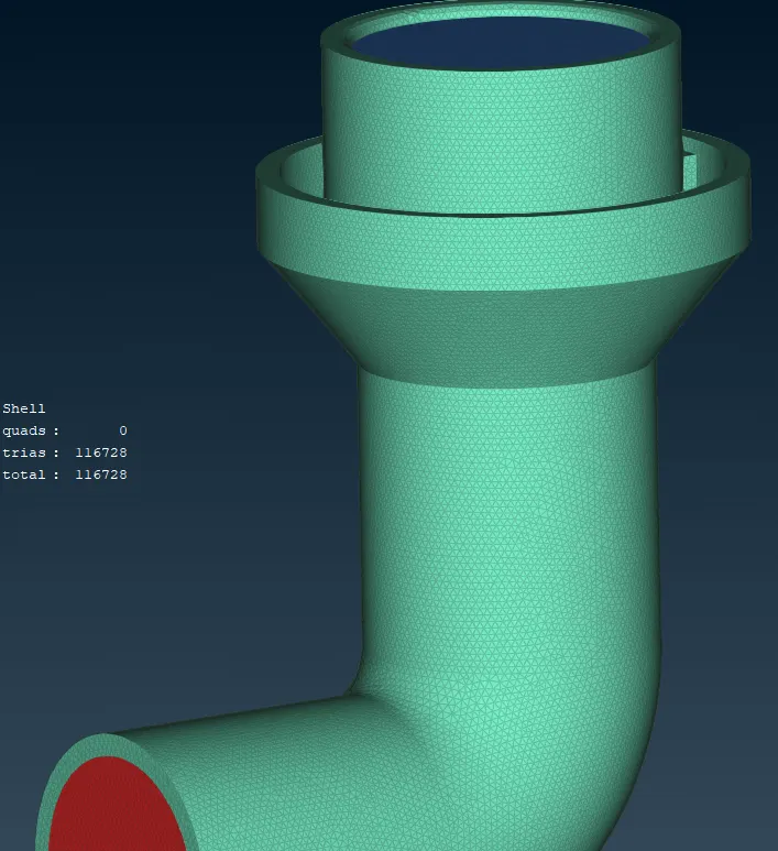
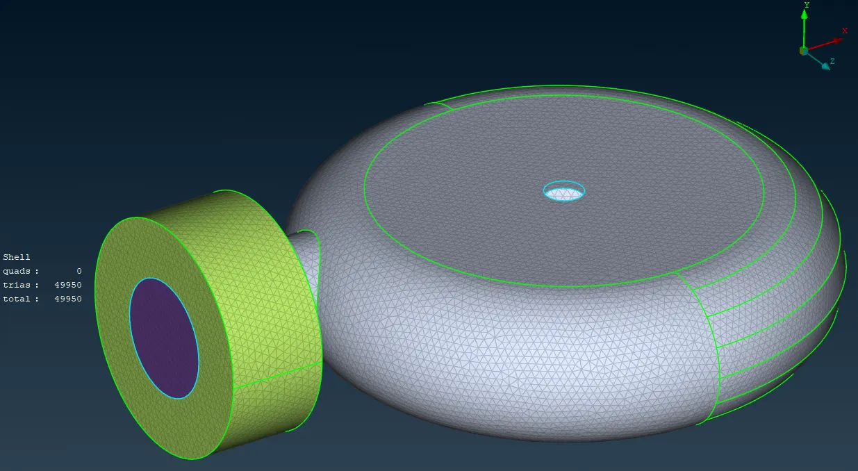
Now meshing for the Impeller, with target mesh length = 2 mm
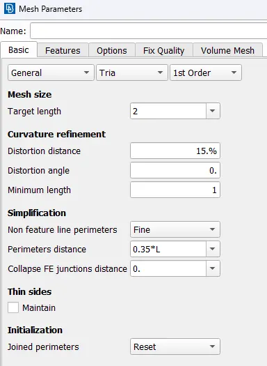
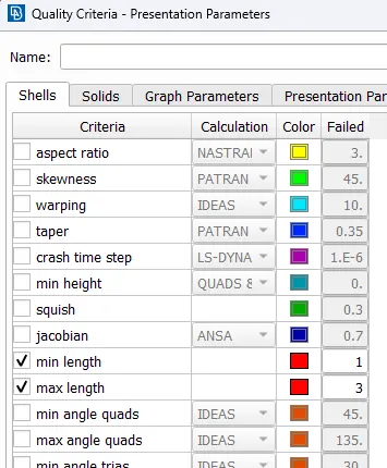
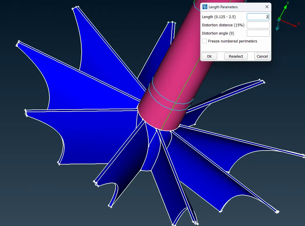
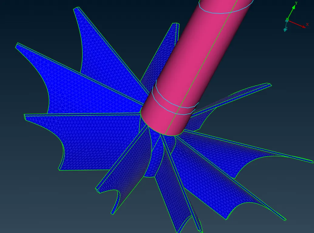
meshing for the Shaft and Blades, with target mesh length = 1 mm
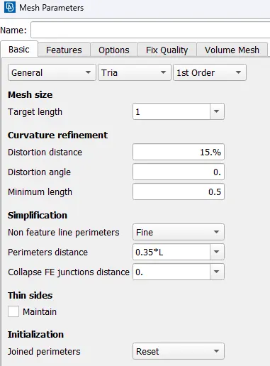
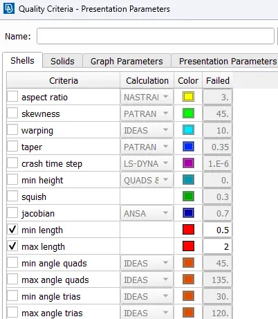
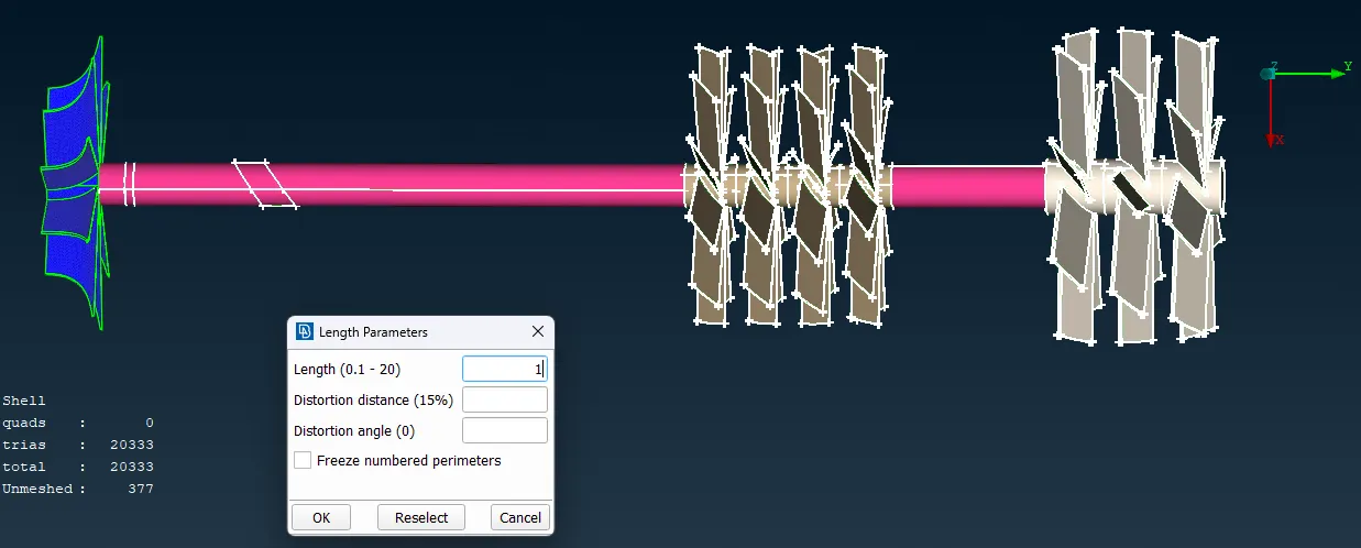
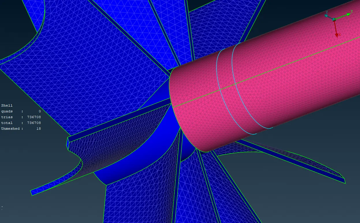
We can see the when we meshed the shaft the intefacing impeller faces become unmeshed.
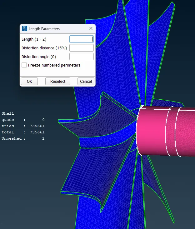
Therefore inorder to solve the mesh near the transitioning faces we just have to remesh without writting in the length parameter. By Default you can see range 1-2 , which will create transtion mesh between length 1mm -2 mm.
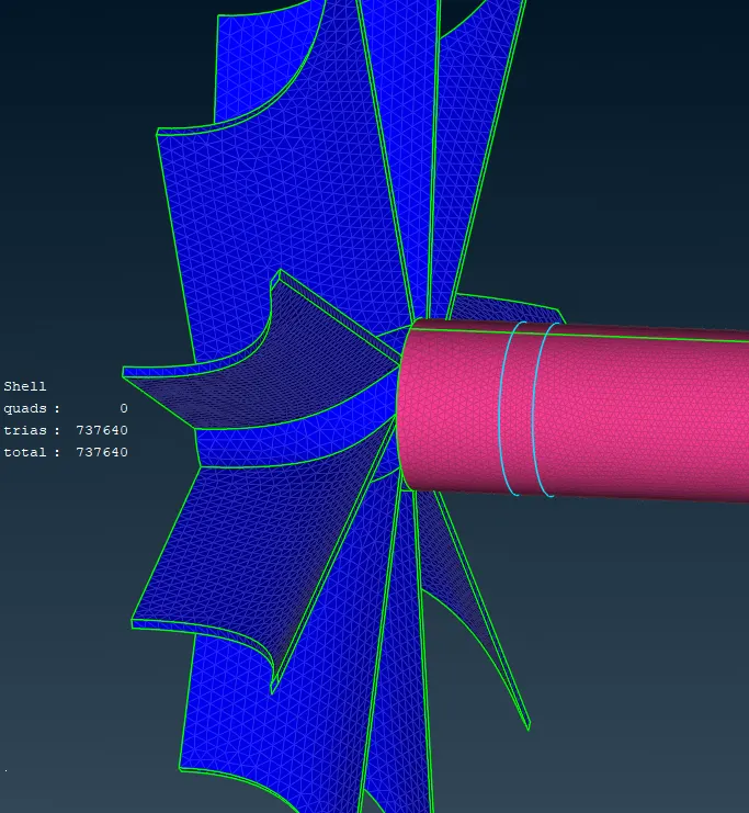
Creating mesh in the hidden unmeshed faces, similiar to above.
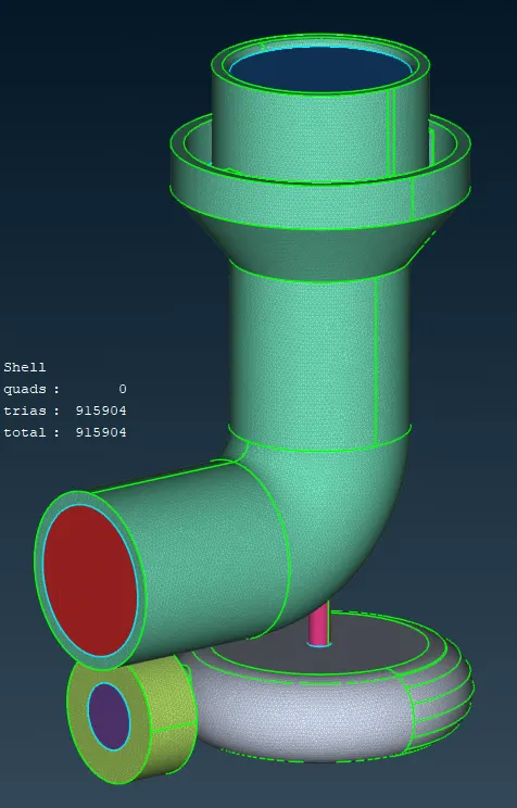
Following is the completed Surface mesh.
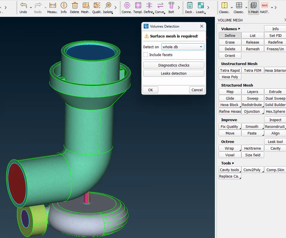
After completing the surface mesh, we can go to volume mesh deck for proceding volume meshing.
By define option we can check/scan for the volumes from the surfaced mesh geometry.
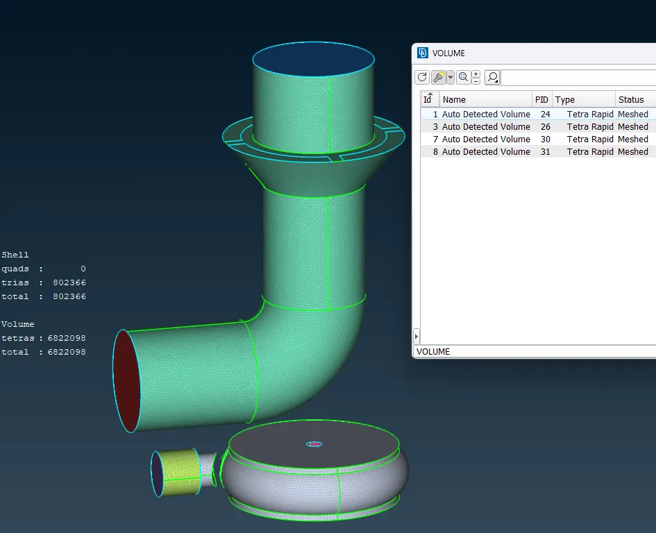
Following are the detected volumes
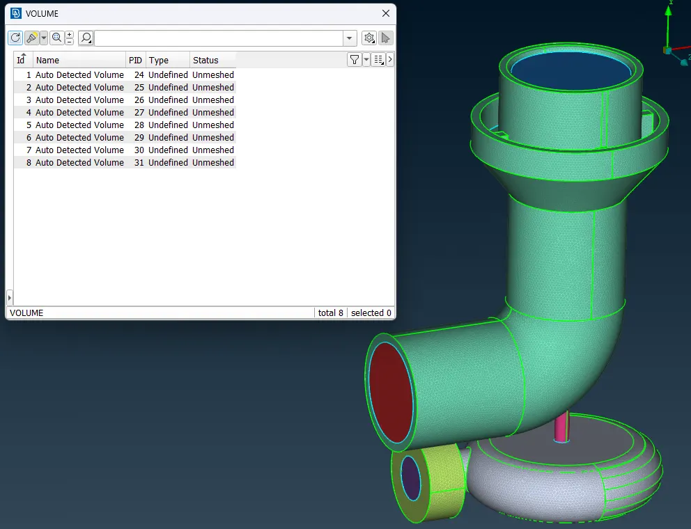
We will delete the Solid volumes which are the body of the turbocharger and just keep the fluid volumes.
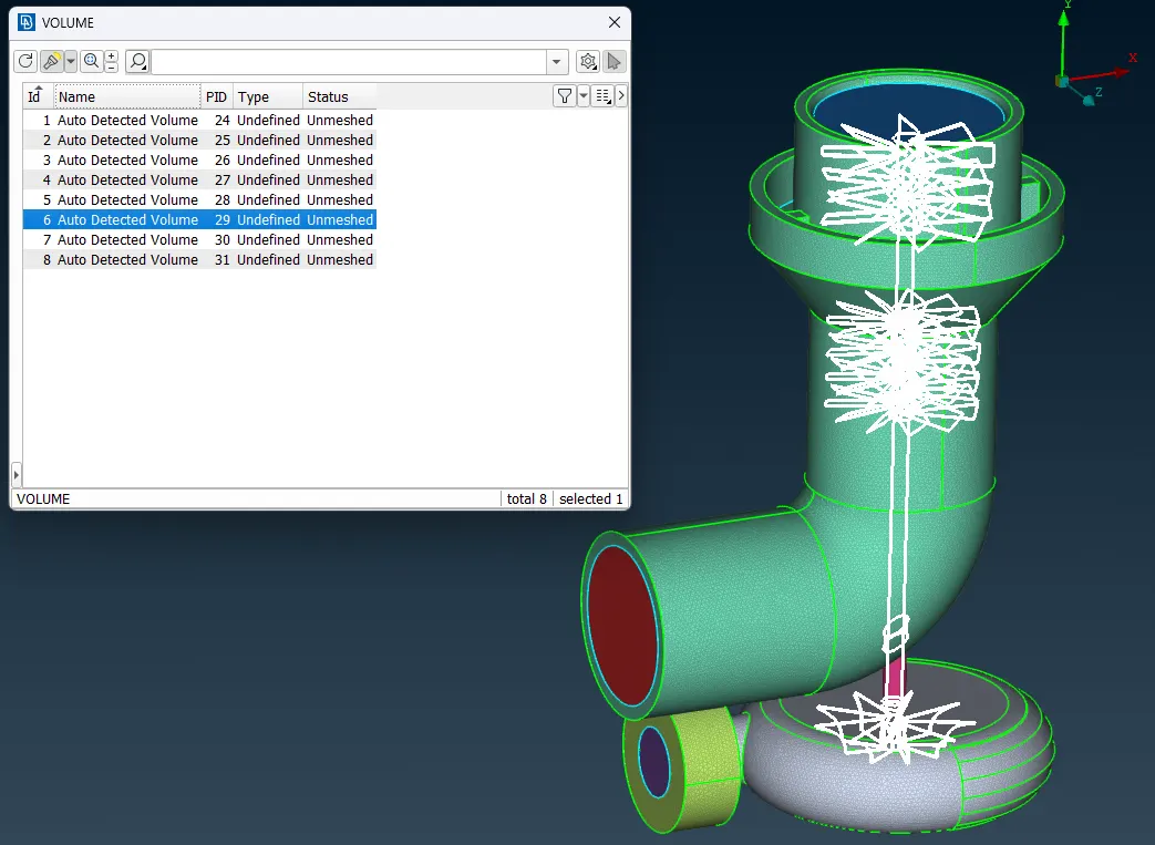
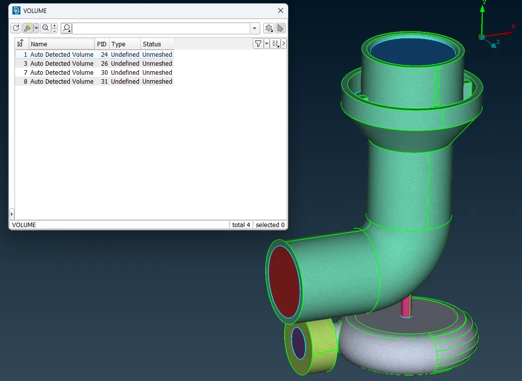
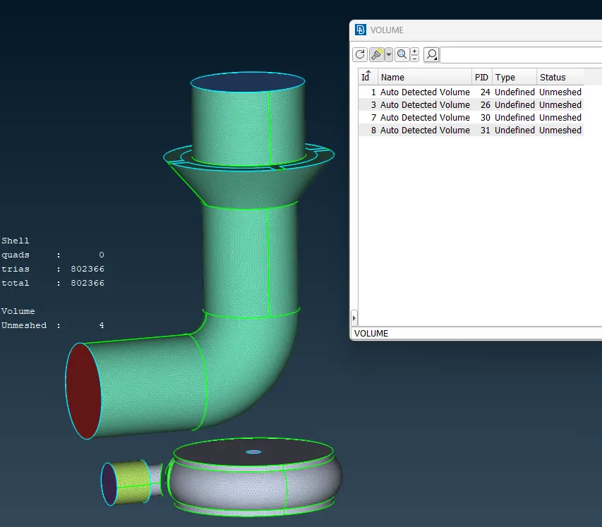
After deleting solid volumes. From the properties tab we can see the mesh status.
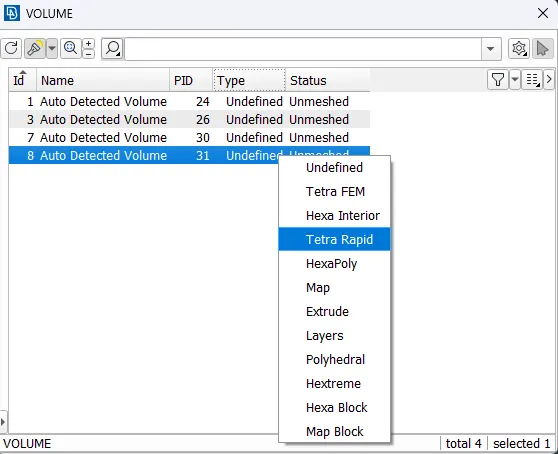
by clicking over the unmeshed tab, we can see different meshing option and we gonna use Tetra rapid option for optimal meshing.
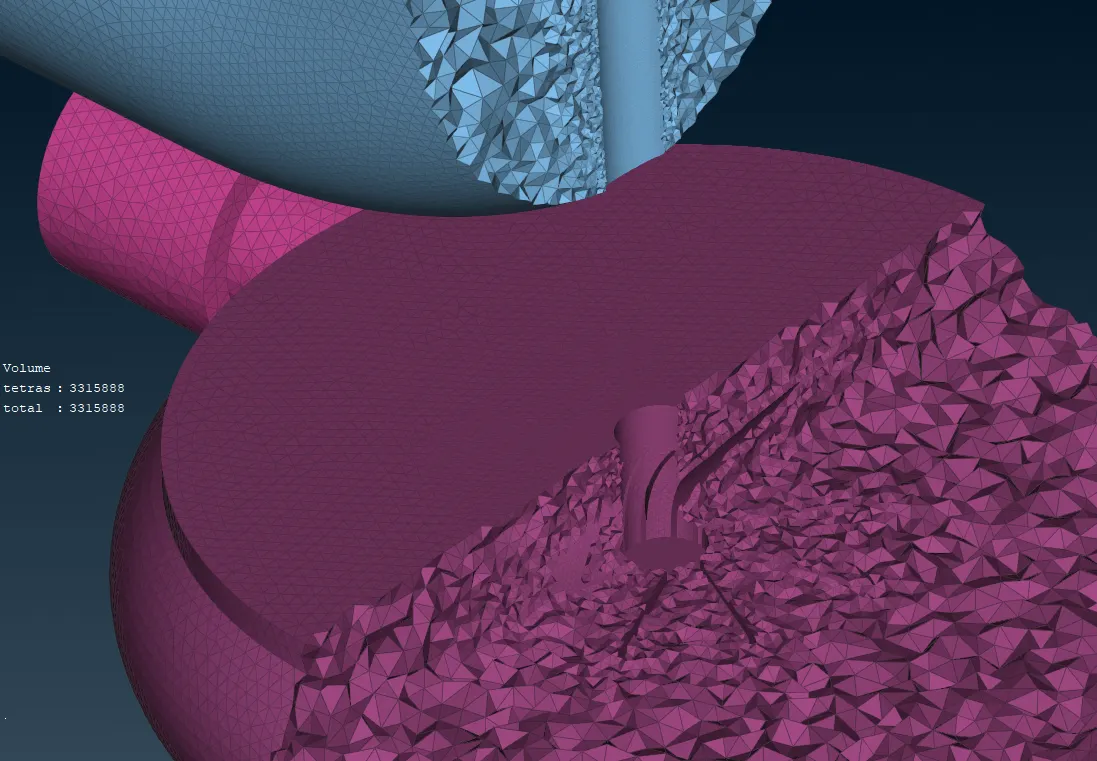
after that we can see the following genrated volume mesh.
RESULTS :
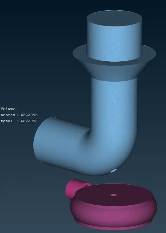
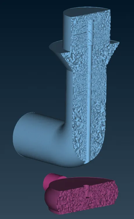
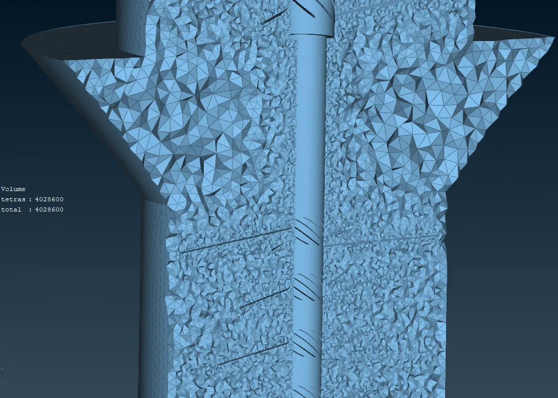
The Following are the results after generating the mesh
Total no. of elements created in the surface mesh = 915904
Total no. of cells created in the volume mesh = 6822098
CONCLUSION :
We have successfully created the mesh for the CFD of the Turbocharger.
We can see that from the above results, as the target length decreases the accuracy of capturing the geometrical profiles near the Blades shaft and impeller. For optimum mesh the nesh mesh near the surface where the Fluid flow depends for the simulation accuracy there mesh is fine compared to other region.
REFERENCE :