Week 3 Challenge : CFD meshing on Turbocharger
Aim:
- To perform the surface mesh using target lengths of (i)1 mm at Blade stage-1,stage-2,shaft rotor (ii)2 mm at impeller (iii)5 mm at Turbo casing,compressor casing,Inlet casing cover on the turbocharger.
- To perform a volumetric mesh on the Turbocharger.
Procedure:
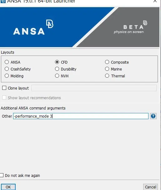
1.Start->ANSA ,ANSA Launcher will opens up by default ANSA Layouts will be selected it should be changed to CFD layout to improve the accuracy of simulation results by making the suitable mesh for the solver (or) based upon the type of the problem .Additional ANSA Command Arguments are provided by default as -changedir it is changed to -performance_mode 3 to have the good drawing quality and slower drawing performance.
2.File->Open,Open window will appears,Locate and select the file and click Ok button.
3.Model appears in the display and FacesDraw-> Drawmode will helps to specify the color for the entities .Draw mode->PID assigns the colour based upon property draw colour.on the model surface appears with two colours then it represents the presence of two property IDs at one surface means of overlapping the faces. TOPO>Faces>Topo option is selected and then region has selected using box select this is done by leftmouse button clicked and dragged over the region and scroll button is clicked then Displayed model shows type of CONS. 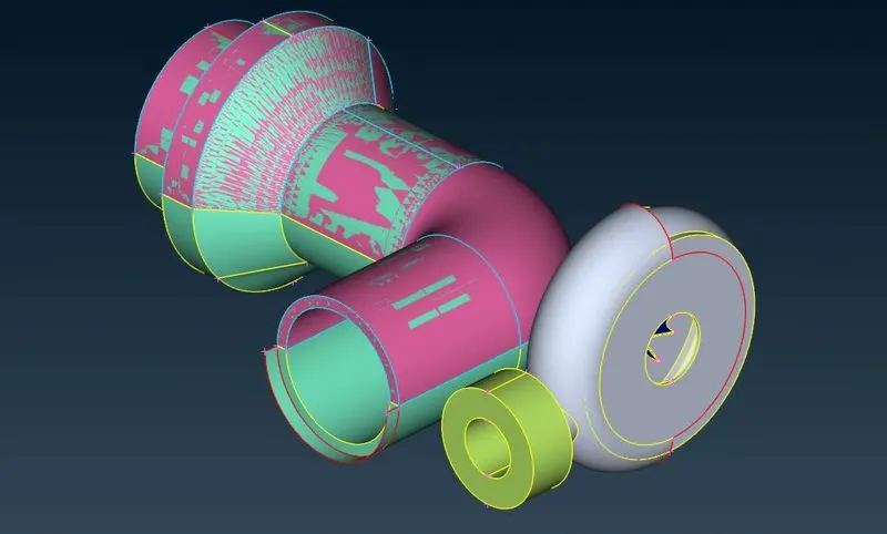 Topo-This fuction automatically defines a topological condition for the selection region or inbetween CONS.
On overlapped surfaces shows triple CONS.missing surface represents by single CONS.
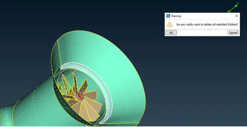
4.Enabling the crossHatch option FacesDraw->CrossHatch it displays same the lines with same colours of the property draw colour.Focus->Not is used to hide the green part then selected using the PID option then left-clicked. Utilities->Delete option is selected to delete the overlaped surface,Region can be selected Using PID option for overlapping surfaces then scroll button is clicked and Focus->All is used then extended surface would be selected using entities option and scroll button is pressed then warning window appears click ok button.
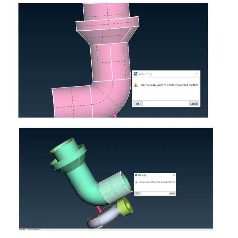
Delete-This function deletes Various ANSA Entities (curves,faces,FE model entities etc..,).This function frequently used for converting of triple CONS to double CONS (or)overlapped (or) Extended surface,that's why mentioning the common procedure
Procedure for Deleting surface:
1Utilities->Delete option is selected.
2.Select the entities to be deleted, one by one, using the left mouse-button, by a box (or) a polygon (or)PID (or)PID Region selection area from Feature Selection toolbar.
3.if necessary, deselect any of the selected entities using the right mouse-button.
4.Confirm the end of entities selection with the middle mouse-button.
5.As the selection is confirmed, all the selected entities are deleted by selecting the ok button with the help of left-mouse button on the warning window.
Crosshatch-Isoparametric lines of the surface is visible and it is used to select the surface.
PID Selection tool-it used to select the region with same property ID of leftclicked at mouse on the entity.
PID Region selection Tool-It is used to select the attached regions of the same property IDs of left clicked at mouse on the entity.
5.Errors related to Single CONS should be solved.Single CONS solved with the help of creating a missing faces or deleting the extruded surfaces.Approximately Four regions of boundaries consists of single CONS .Topo->Faces->New option is selected then new face options window appears COONS algorithm is selected ,then the region is selected then scroll button is clicked and COONS window appears and ok button is pressed.Region is selected based on entities or loop option.
(i)The region selected by using loop option for (a).
(ii)The region is splitted by inserting node points by using Topo->Hotpoints>Multiproject option,Multiproject window appears nodes is selected, then select the points ,then scroll button is clicked and then Selection window appears then CONS option is used to project the node points on the particular CONS,CONS is selected using leftclick at mouse on the Entities and then scroll button is clicked.This will split the cons that’s why creation surface procedure followed for five times shown in above picture from (b) to (f).
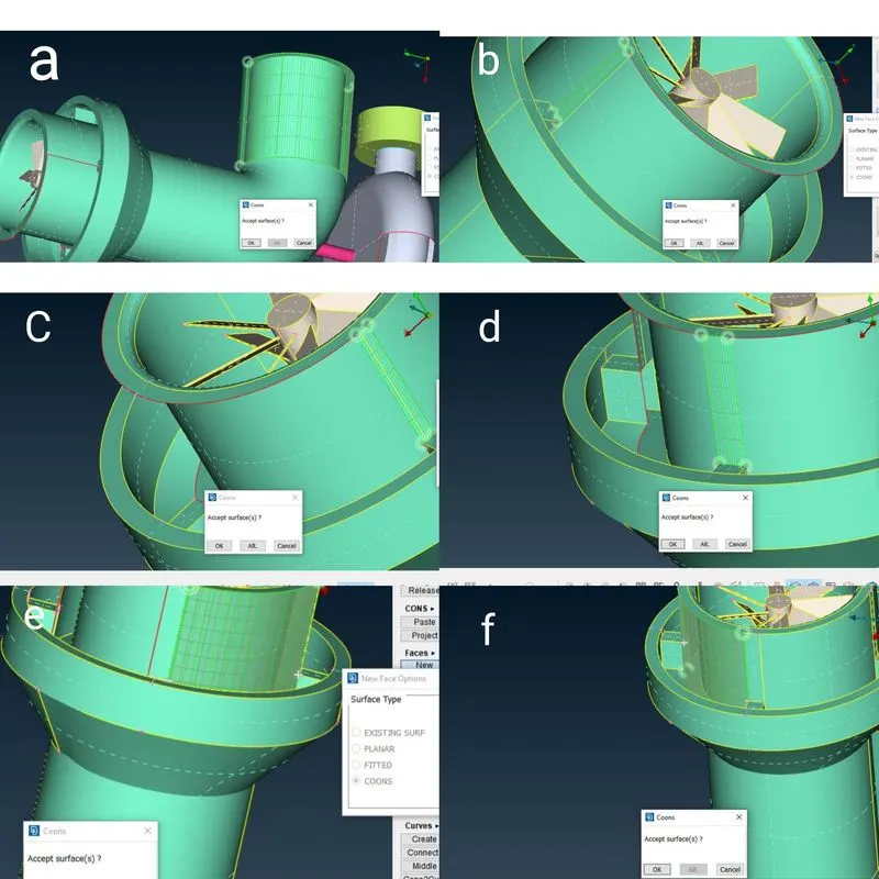
(iii)Topo->hotpoints->parametrical option is used to insert the hotpints.parametrical window appears then CONS is selected to specify the direction and u par value 0.5 is entered and clicked ok button.This procedure done for creating another six hotpoints on the same boundary and then this procedure followed for creating seven hotpoints for another boundary.Creation of faces depicted in the below picture.
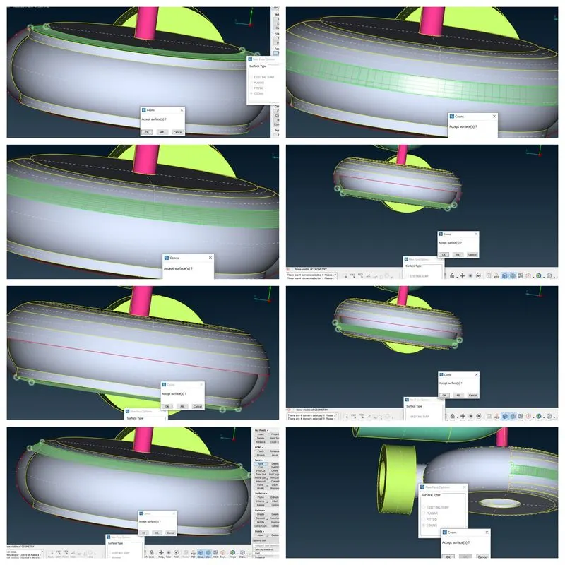
Procedure for creating new surface:
1.Topo->Faces->new is selected.
2.new face options window appears ,which provides a list of unique algorithm.Each and every algorithm behaves differently for different geometric conditions.
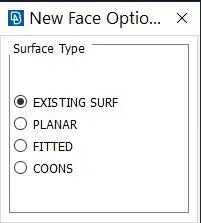
3.Select one by one the CONS segments or the 3D-curve segments that will compose the boundary of the new surface.Feature selection toolbar provides a list of features such as Entities,loop,PID Neighb,Polygonal selection etc.., The selected segments must be consecutive. Discontinuities are usually replaced automatically by smooth CONS segments. At the end of selecting the boundary curves, press the middle mouse-button.
4.If Existed surf is selected,to select the face crosshatch option is enabled on the facesDraw toolbar.if planar (or)Fitted (or)COONS is selected then window appears with the names of confirmation (planar)(or)Surface Fit (Fitted) (or)COONS
5.Accept or reject the definition by pressing OK or Cancel to the relative window. An interesting feature of this function are the alternative (Alt.) Surface definitions that are provided if not closed sides were selected, assuming that the rest of the sides (at least three) can define such a surface.Switch between the two alternative solutions using the Alt. button. The first alternative definition has a linear fourth side.The second alternative definition is a Surface with a fourth side having the same morphology as its opposite one.
When possible, the surface is set automatically to a relative part. If not, the 'Parts Manager' window appears in order to select the part where the new surface will reside, or select from the screen an object and use its part.
When possible, the Face PID is automatically set. If not, a 'Property Selection' window appears, so the PID of the new surface may be selected, or select a face from the screen to use its PID.
6.Two surfaces are crossing but no CONS are displayed to know that Topo->Faces->intersect option is used.IntersectFaces/shells window appears selecting first option then surface is selected using entities option then scroll button is clicked,then second option selected on the intersectFaces/shells window then surfaces is selected using entities option and then scroll button is clicked.window appears would be closed, this will split the surfaces.Deleting the two surfaces as per procedure,Surface selected by entities option.
Intersect-This function defines the intersection between two groups of Faces and/or FE elements that penetrate each other. Topology can be applied automatically if required.
7.After deleting the intersection faces,Found the overlapped faces at the center.Deleting the surface procedure follows in a described way,surfaces selected using entities option.
Topo->CONS->Release option used to release the Triple CONS to the Single CONS by selecting the CONS and scroll button is clicked
Topo->Faces->Topo option is selected then CONS is selected using box select then scroll button is clicked.This would be done for hiding the triple CONS (orange part is hided using Focus->Not and then using pid option surface is selected)
Release-This function releases CONS which have been automatically joined (pasted) or were joined by the CONS->Paste function.
Topo-This function automatically creates topological conditions between selected adjacent CONS
8.To identify the presence of triple and single CONS by FacesDraw->Crosshatch,Perim points is deselected and then DrawingStyles->Shadow is deselected.
Single CONS is displayed as Red line.
Triple CONS is displayed as blue line.
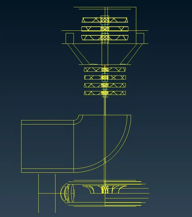
9.On the top Blade stage-2 Single CONS is visible,Triple CONS mostly appear at Blade stage-1 ,Stage-2.As we can see to make visible of solid model by using DrawingStyles->Shadow option is selected.Even the presence of Triple CONS doesnot mean as error.Delete of any one of the surface may give Double CONS but it represents distorted geometry.
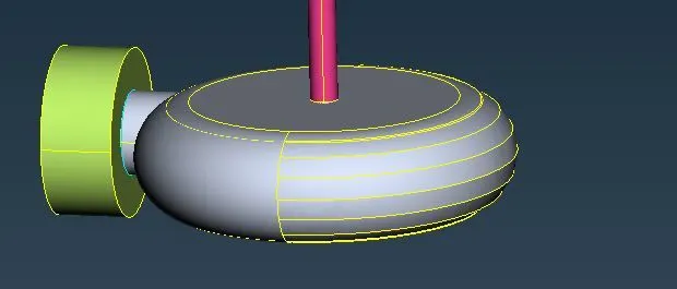
10.Using focus->Not option to hide all the solid except the shaft ,impeller,blade stage-1,stage-2 .Selected using the PID option.it shows the triple CONS present in it.Presence of triple CONS on Blade Stage-1,Stage -2 due to the similar reason.that reason is the presence of additional surfaces in the shaft.Depicted on the below picture
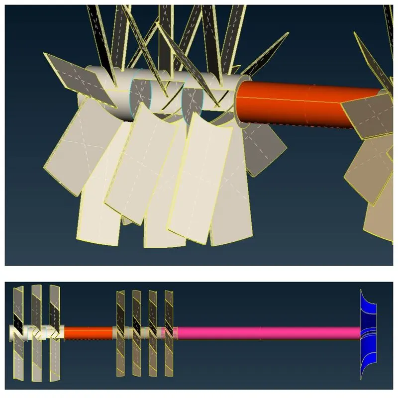
Focus->Not option is used to hide the curved surface of the cylinder ,then selected the surface using entities option.then Utilities->Delete option is used to delete the cylindrical planar surface.Two cylindrical surfaces has selected using the entities option then scroll button is clicked then warning window appears on that ok button is selected.This procedure would be repeated for another five times for the triple CONS present on the blade stage-1 and stage-2.
11.Overlapped Surfaces presence will be deleted.Topo->CONS->Project option is used then CONS is selected by using entities option then scroll button is clicked then Face(shaft) is selected using Entities option then scroll button is clicked.Procedure of deleting surface is followed.Two surfaces are selected by entities option.
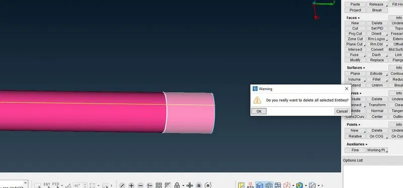
12.Triple CONS once again appeared at the interface of shaft and blade stage-2 due to the presence of circular plane surface.Procedure of Deleting surface is used.Surface selected by entities option.
13.Overlapping surfaces will be present at the interface of the impeller and shaft.The shaft has the circular plane surface at the interface and the impeller does not has.Due to this Topo->CONS->Project option is used, Focus->Not option is used this will hide the impeller ,CONS is selected using box select and then Focus->And will show the impeller and Focus->or is used to hide the shaft then selecting the face of the impeller using entities option then scroll button is clicked ,then Utilities->Delete option is used then surface is selected using entities option scroll button is clicked warning window appears then ok button is selected.
14.Focus->All is used then Tools->Checks->Geometry option is used to found the errors,Execute is clicked.
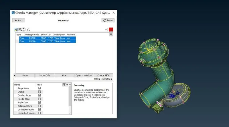
Triple CONS present here is essential for geometry.
15.Lists->Properties option is used then right click on the properties ,edit option then shell property window appears name should provided and the ok button is clicked.Repeated this procedure for seventimes that the PIDs are renamed.shaft has two PIDs changed into single PIDs by using rightclick on shaft PID->Apply ,surface is selected then scroll button is pressed.Empty PIDS is Both are deleted using Utilities->compress option ,on the compress window ok button is clicked.
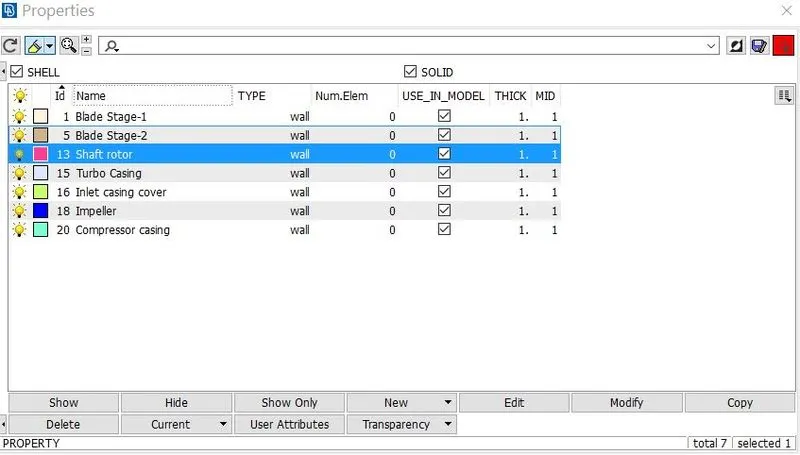
16.On the property Window,right-click then new->Shell_property option is selected then shell property window appears providing the names for the new PIDs then Ok is clicked.this is repeated for four times to create new PIDs.
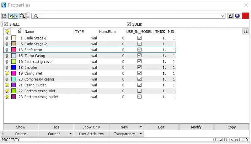
Compress-By this operation, all information concerning deleted entities is lost.
For CFD mesh the volume should be closed,but geometry still contains openspace to patch that utilising the creation of the face.
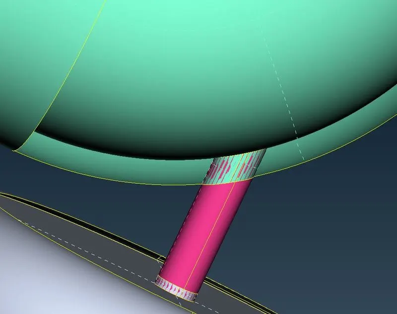
17.overlapping surfaces still present it is depicted on the below picture.procedure for deleting surface is used.Surfaces are selected using entities option.
18.Surface Mesh plays an important role even for volumetric meshing Tools->Properties,then compressor casing,casing inlet,outlet made visible by clicking the bulb shape icon. Utilities->mesh parameters option is used ,mesh parameter window target value is entered as 5 and min,max target length as 3,7 ok button is clicked ,then Utilities->quality criteria is used then quality criteria window appears then min,max length value is entered as 3,7 ok button is pressed,Mesh-> Perimeters->length option is used selection window appears then select perimters,select the model using box select,then scroll button is clicked then macros will be selected on the selection window then all surfaces are selected using box select,then scroll button is clicked.Mesh->mesh generation->spotmesh->visible is selected.then meshing process begins
In the same way and value of parameters for the Turbo casing,bottom casing inlet,bottom casing outlet,inlet casing cover should done meshing at once by deselecting the PIDS visiblity previously meshed
In the same way Impeller PID is meshed after deselecting visiblity of the previously meshed. min (or) mintarget length - 1, max (or) maxtarget length is 3,Target Length - 2 used in mesh parameters and quality criterian and length on perimeters and macros - 2.
In the same way blade stage-1 & stage-2 PID is meshed selected to visible after deselecting the visiblity of the previously meshed.min (or) mintarget length - 0.5, max (or) maxtarget length is 2,Target Length - 1 used in mesh parameters and quality criteria and length on perimeters and macros - 1.
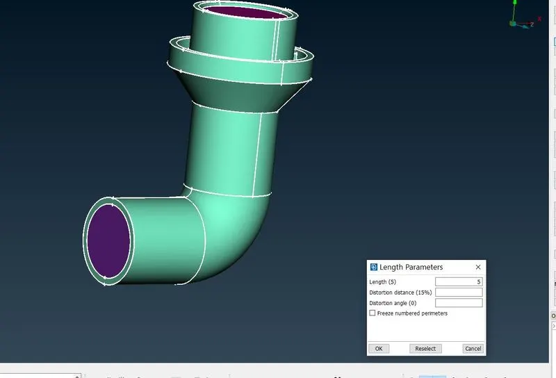
Due to interference has different target lengths,at one surface mesh will gets erased.To avoid situations like that macros length determined automically will be used.Due to this once again meshed Shaft and entity of compressor,turbo casing in the described way of creation of mesh.
19.To see the mesh at the interface,Mesh->macros->cut option is used then creating single CONS by placing the two points.to cut the surface using four CONS on the compressor casing ,then four CONS is created on the turbo casing to cut the surface.
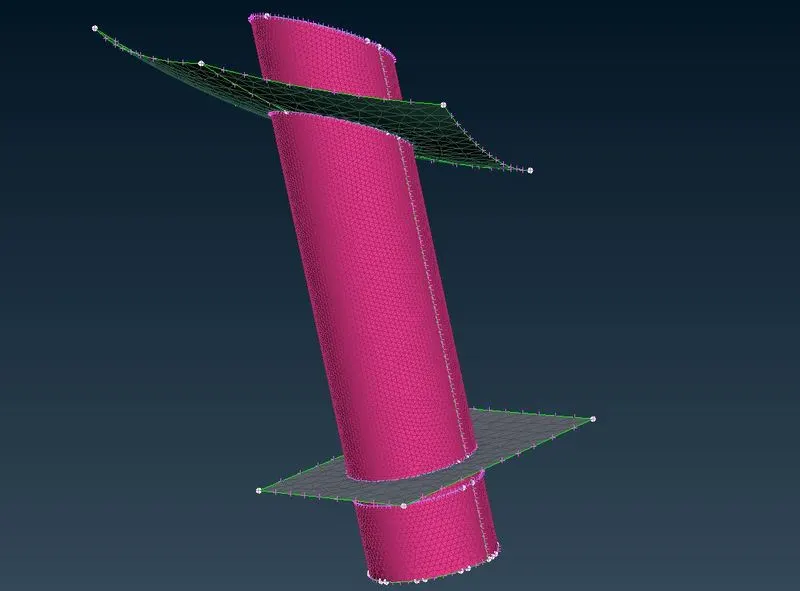
Cut-This function cuts an existing macro area.
20.For Volumetric meshing,initially changed by using a module->V.mesh option,then Volumes->Define->Auto Detect is selected,Volume detect options window will appear ,selecting whole DB for Work on then ok button is used,then volume window will appears with automatically detected volume ,then removed volumes which consists material thickness by right-clicking then delete option is selected for the four volumes then ok button is pressed on the confirmation window.
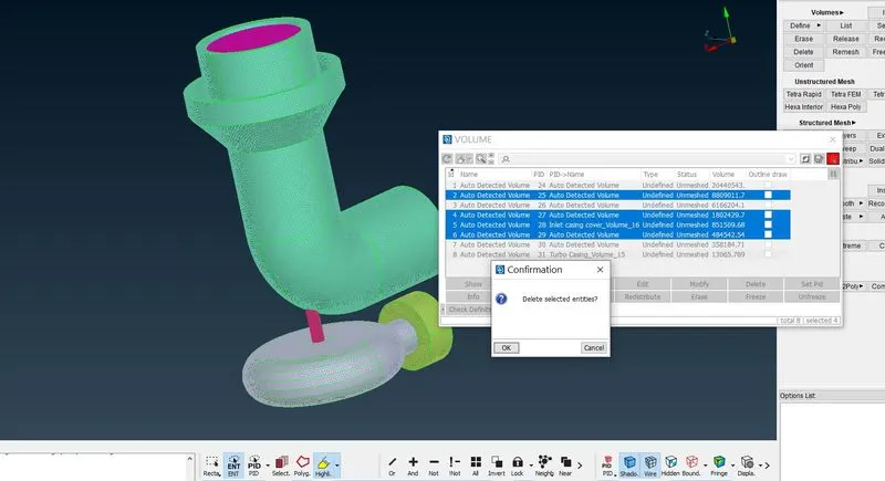
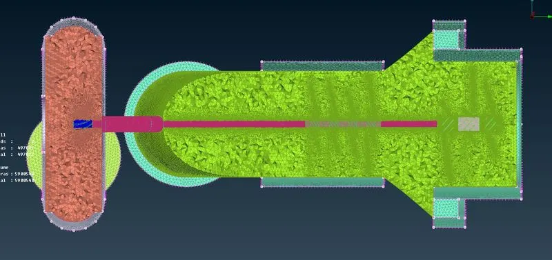
21.on right-clicking the volume button ,remesh option is selected ,volume type window appears selecting TetraCFD and click OK button will creates a volumetric mesh on the selected volume this procedure repeated for 4 times to mesh all.
22.File -> Save button is selected,model is saved on the folder.
Learning outcomes:
- way of handling the pre-processing tool for Geometry cleanup,surface meshing and volumetric meshing.
- For geometry cleanup two important features repeatedly used that is creation of surface,surface Delete
- Creation of Property ID’s for unique components present in the model.
- Learned to assign the element length for the surface meshing,Creation of surface meshing
- Learned to assign the type of the mesh and creation of volumetric mesh.
Pre-processor Result:
Creation of surface meshing using triangular elements and volumetric meshing using tetra elements
- No of Triangular elements-928294.
- No of Tetra Elements-9460580.
Conclusion:
- If Presence of missing surfaces in the model,Creation of new surface is necessary but the missing surface is Complex 3D surface then spliting up before creation of surface also becomes necessary.
- At some point,Software (or) Tool wont update automatically in terms of CONS then Each and every time utilising Release or Topo feature ,that would be the necessary.
- Surface Meshing grabs attention for meshing the surfaces with the different target lengths.
- Volumetric meshing provides the options to select the mesh type based on the applications.
- Volumetric meshing near the wall meshed with smaller elements like the boundary layer.when compared to the largest mesh elements away from walls.
File is uploaded on the zip format :https://drive.google.com/file/d/18mnczPEKjuOx56OVLUHL9lKgUhCnizDp/view?usp=sharing