Week 3 Challenge : CFD meshing on Turbocharger
OBJECTIVE :
For the given model, To check the geometrical errors and to make appropriate volumes and do volumetric mesh for the given model. Here the given model is Turbocharger
PROCEDURE :
To do a volumteric mesh for a model , Following procedures have to be done
- Topo cleanup
- Surface Meshing
- Volumetric meshing
1.Topo cleanup
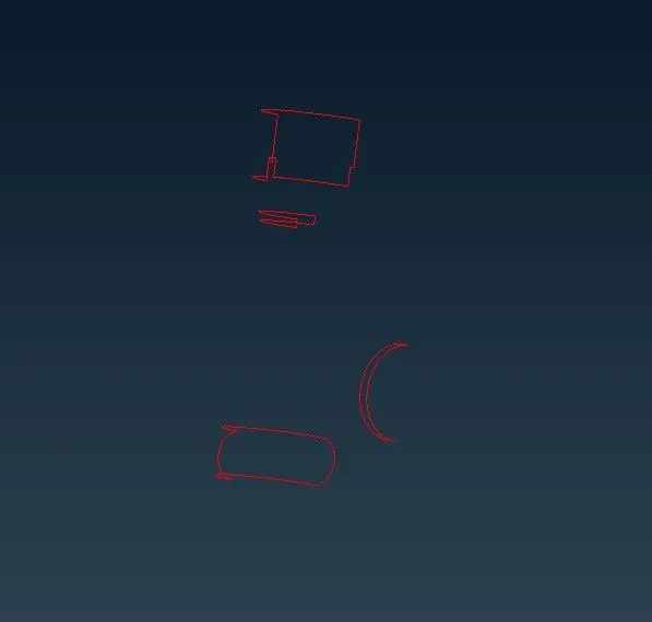
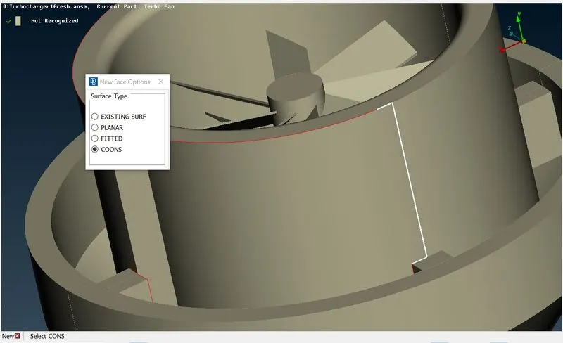
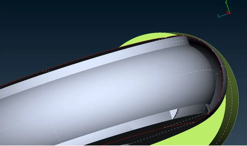
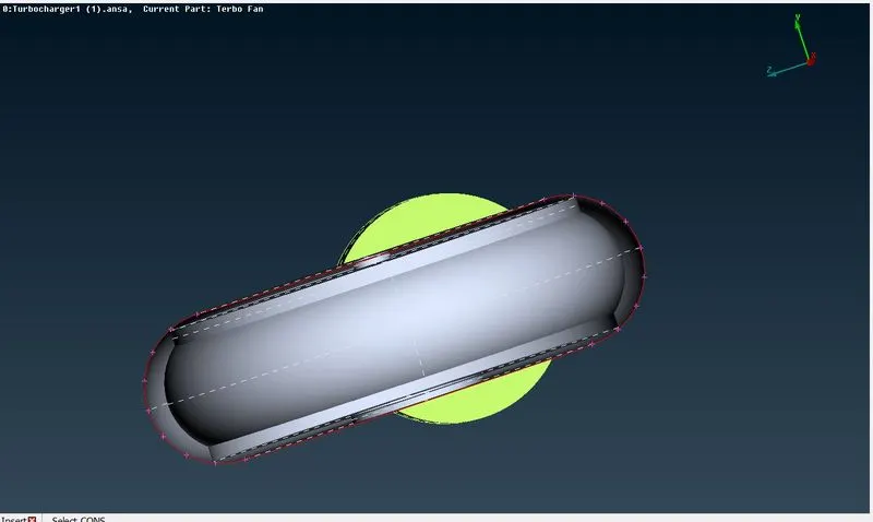
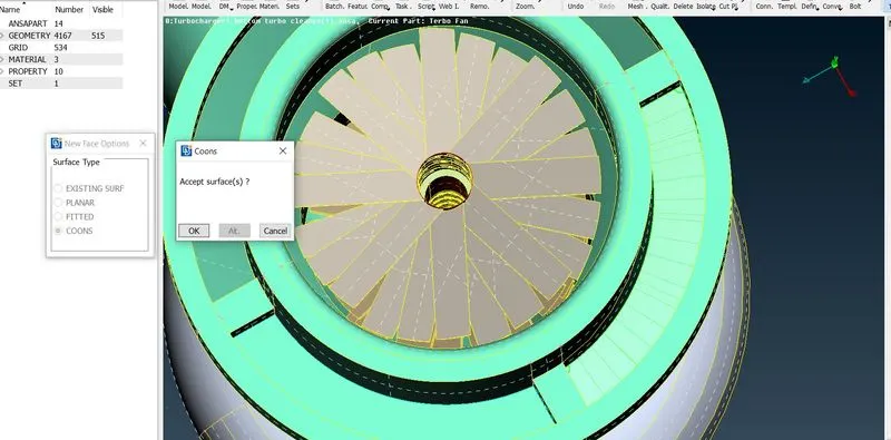
Topo cleanup is the cleaning the geometrical errors and making completely to get rid of single con as there are no pending surfaces to be filled . Hereby I attach my images that were screenshoted while I was working .
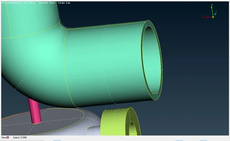
- creating new faces to make single con o double con
- after topo cleanup, model has to be covererd water tightly for surface meshing
2. Surface meshing
Surface mesh has to be one for the model as it stands as the precursor for volumetric meshing
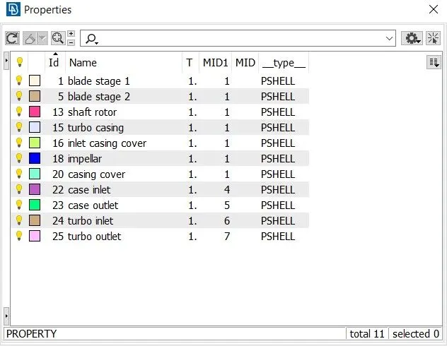
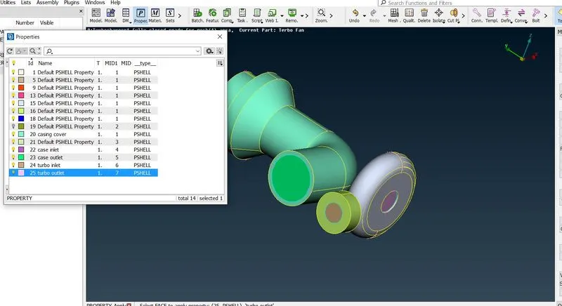
- PIDs are identified here, classifying the PIDs makes better identification for the parts in the model to be meshed
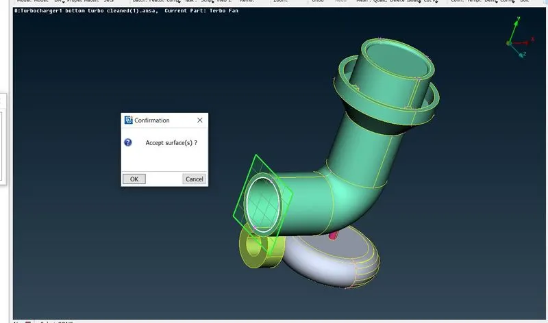
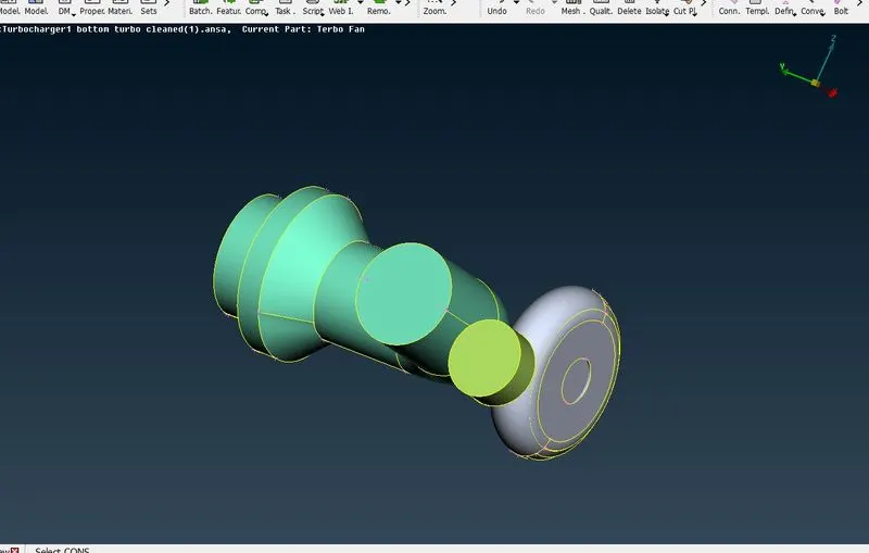
- Inlets , Outlets are engaged for closing the model completelely
- Each PIDs are made to mesh with different length as given here
- Every PIDs have mesh type as tria .
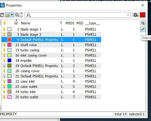
PIDs are identified and changed to
closing the model with inlets and outlets
While doing this operation ther may arise triple cons and overlay
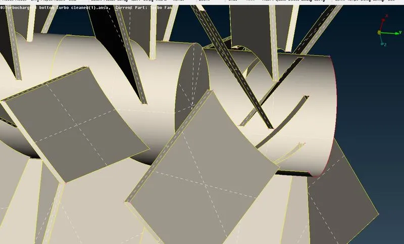
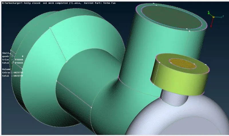
Finally the model having zero single con
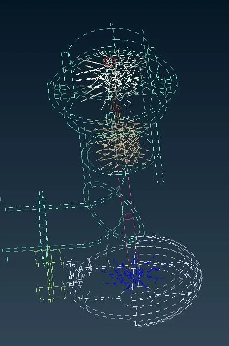

Surface mesh is done
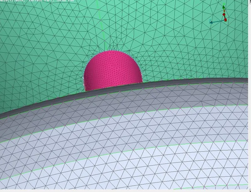
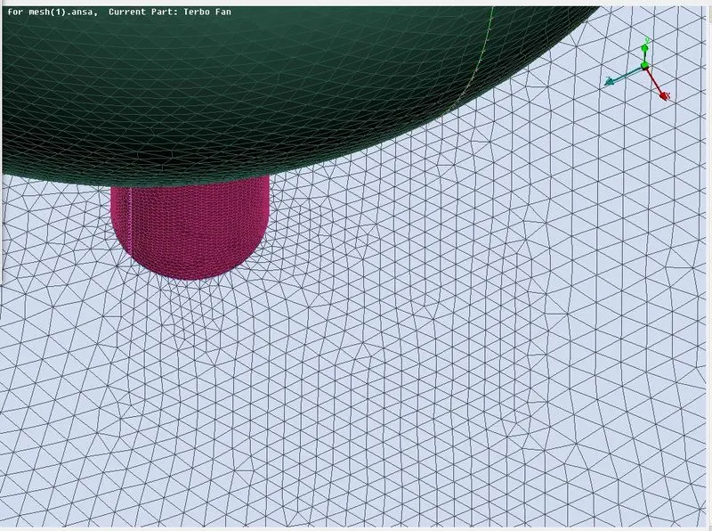
- Uneven mesh quality arises at boundaries of PID models having different mesh lengths
- These can be resolved by again giving the meshing paramters and doing spot mesh by selecting the entities that are to bare different flexible mesh lengths and paramters.
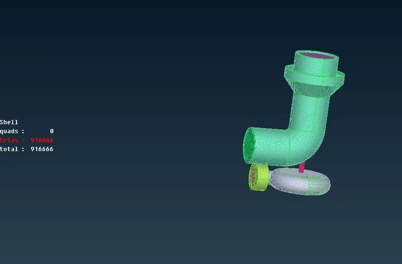
3.Volumteric meshing
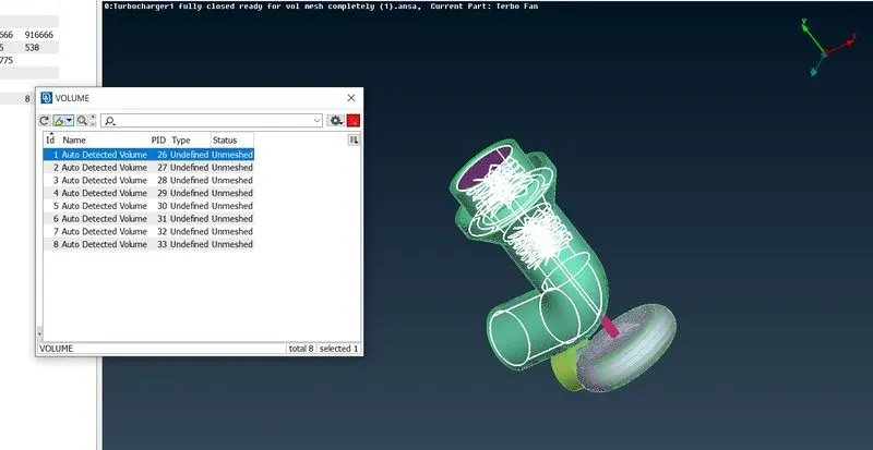
Voumteric meshing is done by defining the volumes and meshing it. Volume detection is done by auto detection of the ansa software
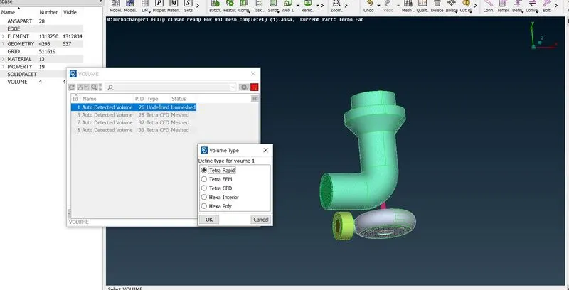
- After auto detecting the volumes of the model given . Only the volume where there would be a void space for fluid flow is selected for volumetric meshing
- Those volumes where fluid flows must be the volume where it would be helpful for internal CFD applications , If external CFD application are performed then the outer shell thickness should be considered , but in this case we would need the internal volumes alone.
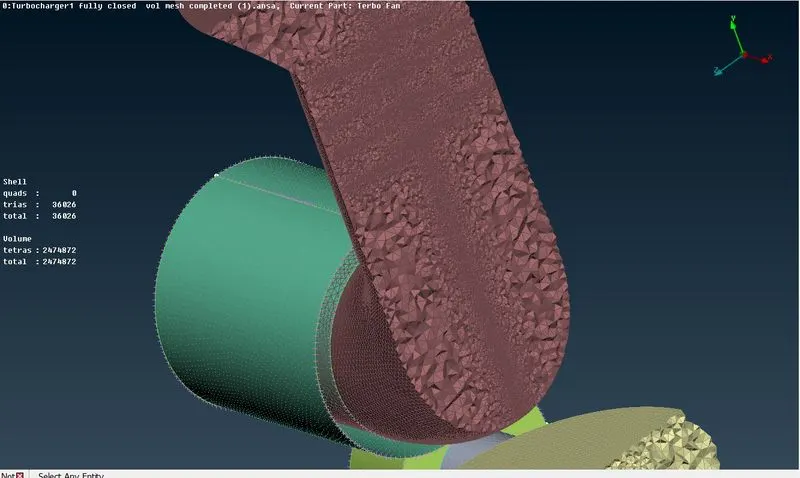
This image shows the cross section of the volumetric meshed Turbocharger, as there are tetra mesh present near the blade areas are small as while doing surface meshing the mentoned mesh quality given for the blades and shaft were 1mm and that for casing were 5mm . So there are a range of tetra mesh ranging from 1mm to 5mm as it the mesh moves from inwards to outside .
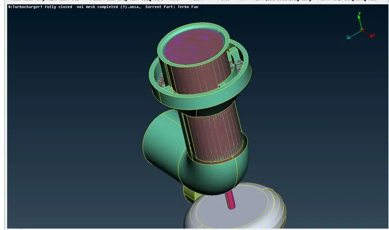
Over lapping can be seen in topo mode as the model is completely volumetric meshed.
Conclusion :
The given Turbo charger model is perfomed volumteric meshing.