Week 3 Challenge : CFD meshing on Turbocharger
Aim: Perform CFD Volumetric Meshing of a Turbocharger.
Theory:
What is a Turbocharger?
Turbocharger (often called a turbo) is a mechanical device which is powered by the exhaust gas flow of an internal combustion engine to increase its output power for a given engine displacement. The main components of a turbocharger include a turbine, compressor, and center housing hub rotating assembly. The turbine extracts kinetic energy from exhaust gases to power the compressor, which compresses the intake air and forcing more air in the engine. 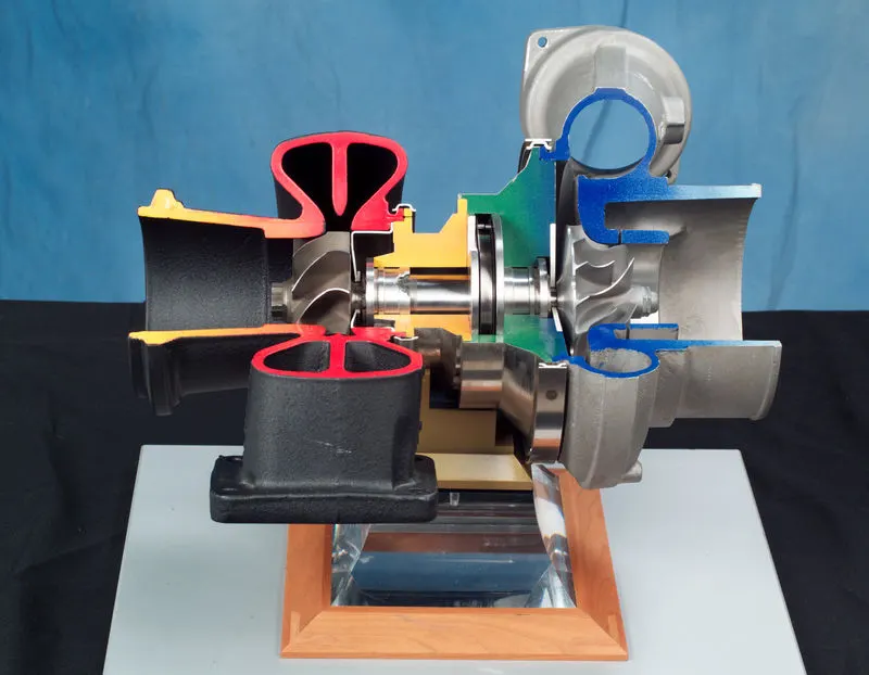
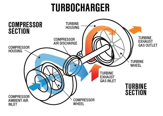
While there's also supercharger and it is similar in its purpose with turbocharger. The only difference being that supercharger is not powered by the IC engine exhaust and has is independently powered by engine. Thus making turbocharger more fuel efficient under certain working range.
Since the objective is for flow analysis the volumetric mesh is to be obtained for the fluid domain.
Setup:
- Importing Geometry.
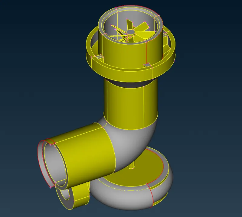
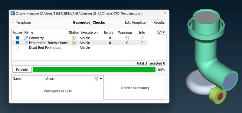
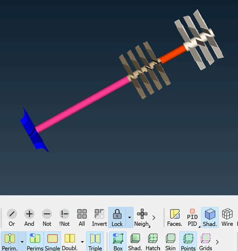
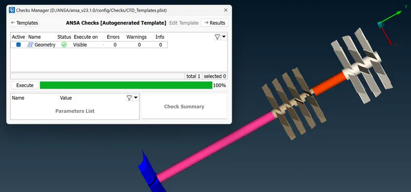
The above geometry is the model on which volumetric meshing is to be done. - While seeing in PID mode it is seen that there are many overlapping faces. These has to be removed using boolean operations to select the faces to be removed and delete option in Utilities Toolbar. The Geometic Checkup is performed to look for SINGLE CONS' in the geometry and also for removing unwanted TRIPLE CONS'.
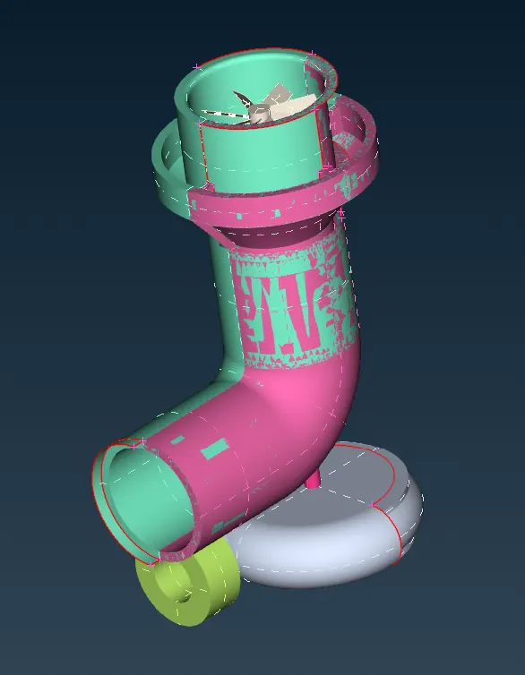
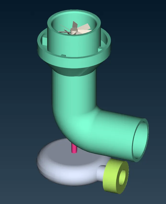
Before topo cleanup After Topo Cleanup
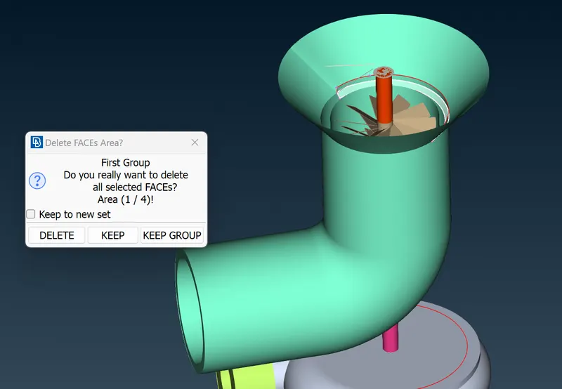
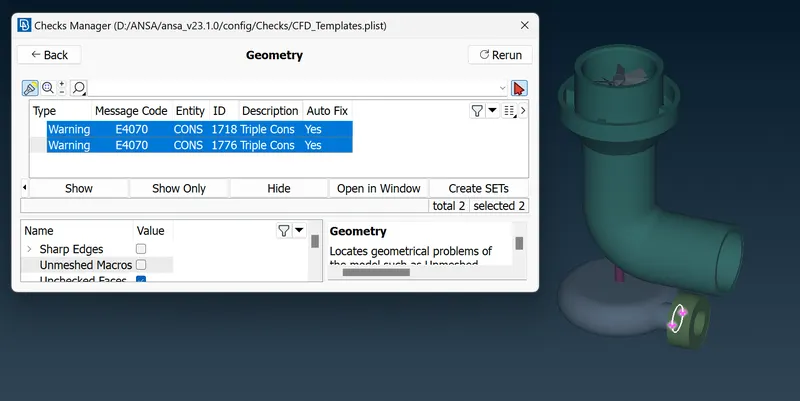
Intersect option for removing unwanted faces Zero Single CONS
- Patching up openings like inlets and outlets of compressor and turbine casings. As the CFD flow requires closed geometry. Also its better to choose PLANAR option in faces option rather than COONS or FITTED as they may cause intersection error further down the line during mesh generation. Basically, intersection error comes from intersection of domains so if there are unwanted surfaces in the geometry that can interfere with fluid domain, such faces must be removed.
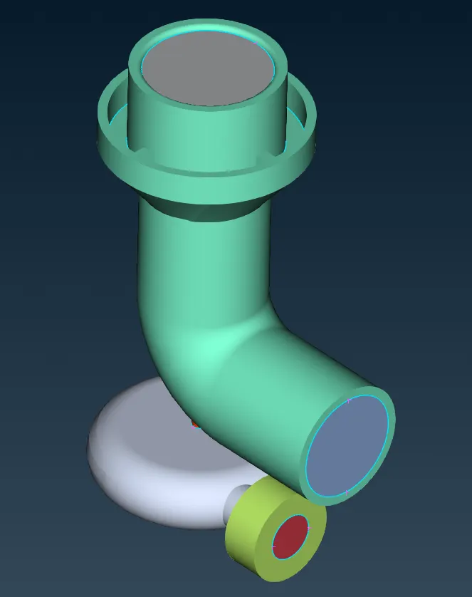
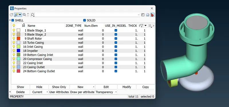
- Redefining PID regions.
- Surface Meshing
Surface Meshing or just meshing is done for the geometry surfaces as these will be the requisites for the volumetric mesh. The meshing requirements for the geomerty are as follows:
Region Length of element Blade stage-1 1 mm Blade stage-2 1 mm Impeller 2 mm Shaft rotor 1 mm Turbo casing 5 mm Compressor casing 5 mm Inlet casing cover 5 mm 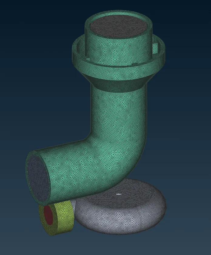
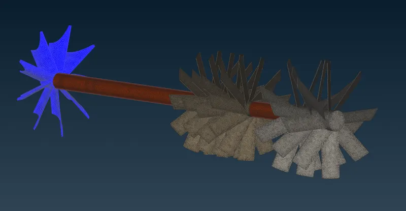
5 mm meshing shaft, impeller and blade mesh
Due to common CONS' sharing different mesh on either sides in certain regions it can lead to disappearance of mesh on one of the either faces.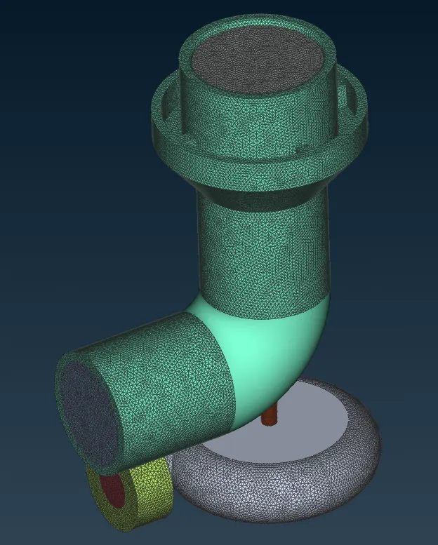
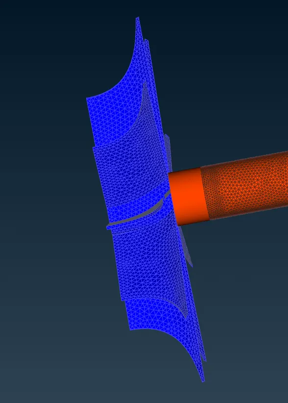
So flexibilty is to be provided in defining mesh lengths so mesh dosent disappear in such regions.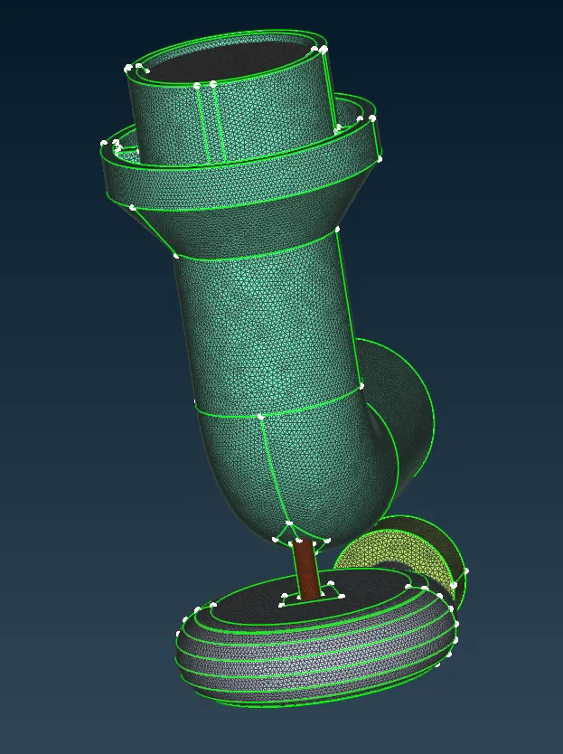
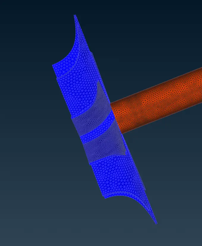
Also, Cut Macros can be used to limit the region of size variation in mesh lengths as shown in above figure on the left as a patch on compressor casing.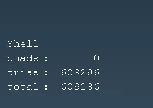
- Volumetric Meshing
Auto Define, for Auto Detection of Volume, is selected by long pressing 'Define' option under 'Volumes'.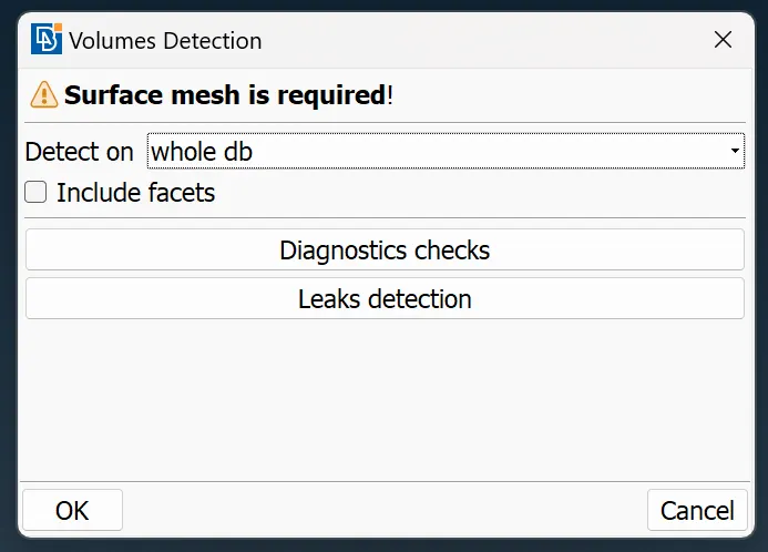
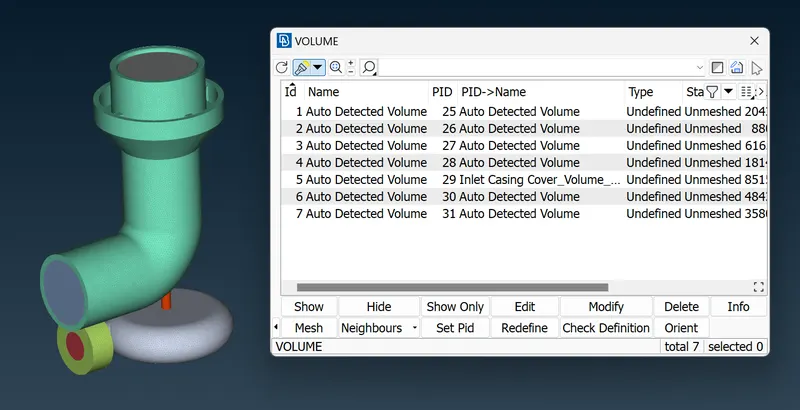
Out of all the volumes only the volumes that are occupied by the fluid doamin is kept rest all is deleted.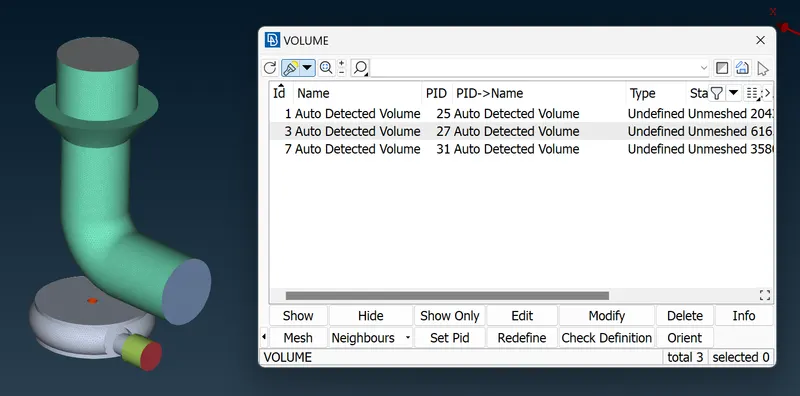
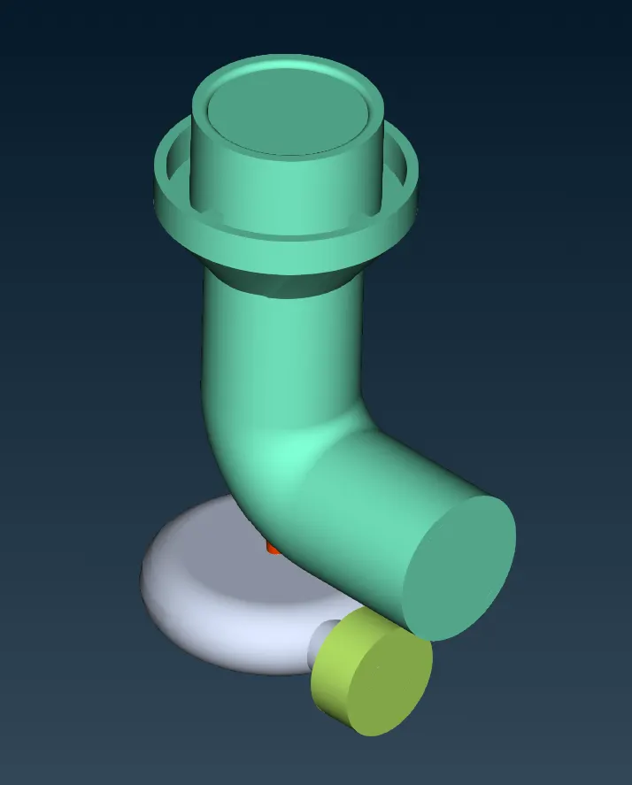
The remesh/mesh is selected by right clicking on volumes in the list. Tetrahedral mesh is selected for meshing the volume.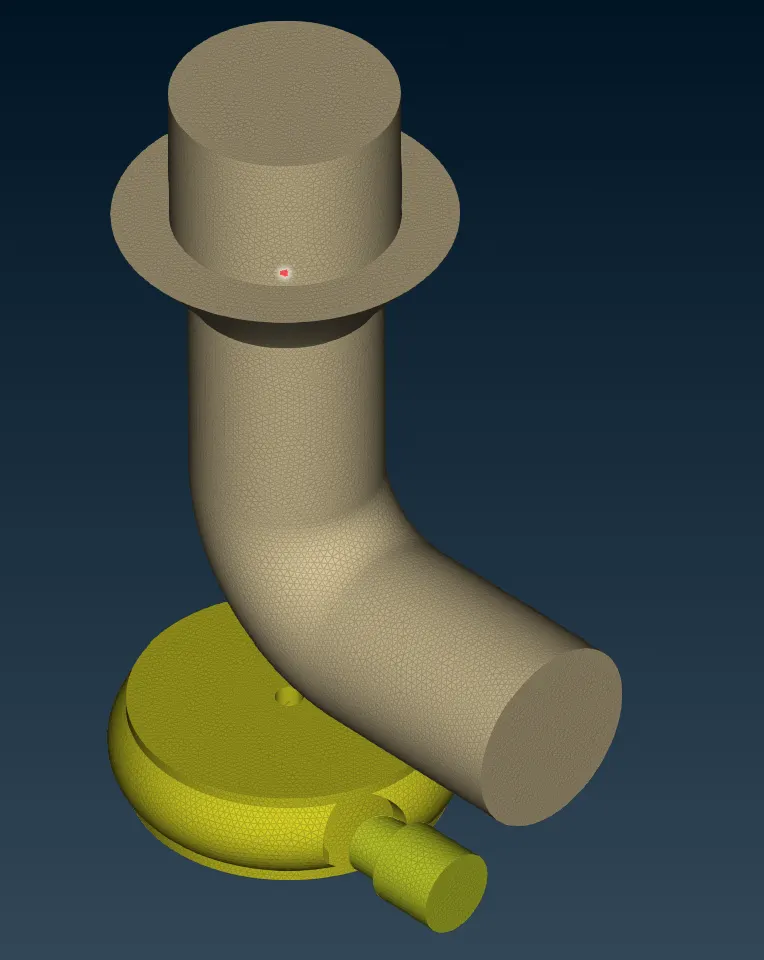
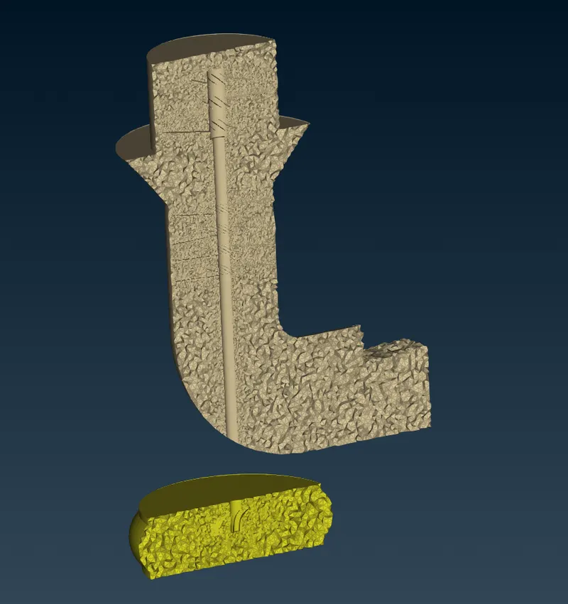
Sectional view shows volumetric mesh in detail. The mesh is much finer near the zones of small mesh length and smoothly transitions into the region of higher mesh length.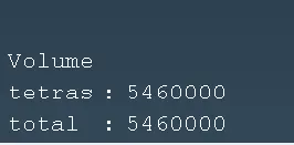
- Conclusion:
- The Volumetric mesh was successfully generated for the turbocharger geometry.
- 3D Mesh count is much higher comared to 2D mesh count.
- Links:
https://drive.google.com/file/d/13QI84SqQaQtTJsrgS1IZKlnDXmcdjt6N/view?usp=share_link