Week 3 Challenge : CFD meshing on Turbocharger
CFD meshing on Turbocharger
Aim:
For the given model, check for the geometrical errors to make appropriate volumes. Create and assign PIDs as shown in the video. Perform surface mesh with the given target lengths as per PIDs.
- Blade stage-1 = 1 mm
- Blade stage-2 = 1 mm
- Impeller = 2 mm
- Shaft rotor = 1 mm
- Turbo casing = 5 mm
- Compressor casing = 5 mm
- Inlet casing cover = 5 mm
Objective:
Turbocharger is a device fitted to a vehicle's engine that is designed to improve the overall efficiency and increase performance.
A turbo is made up of two halves joined together by a shaft. On one side, hot exhaust gasses spin the turbine that is connected to another turbine which sucks air in and compresses it into the engine. This compression is what gives the engine the extra power and efficiency because as more air can go in the combustion chamber, more fuel can be added for more power.
Perform Volumetric mesh for the required volumes as shown in the videos.
Write a detailed report on your surface meshing & Volume meshing process.
Steps
Cleanup Geometry:
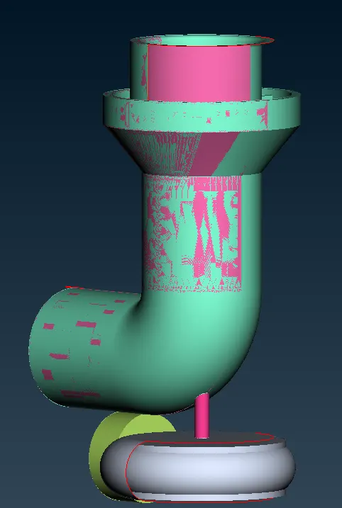
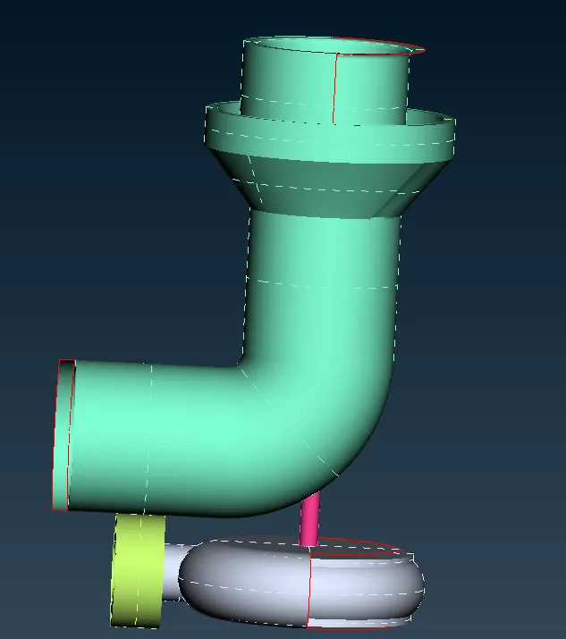
we have double surface so delet one surface
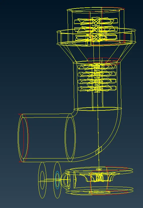
There are more single cons in geometry we should clean all this single cons
we can use new and fill hole options
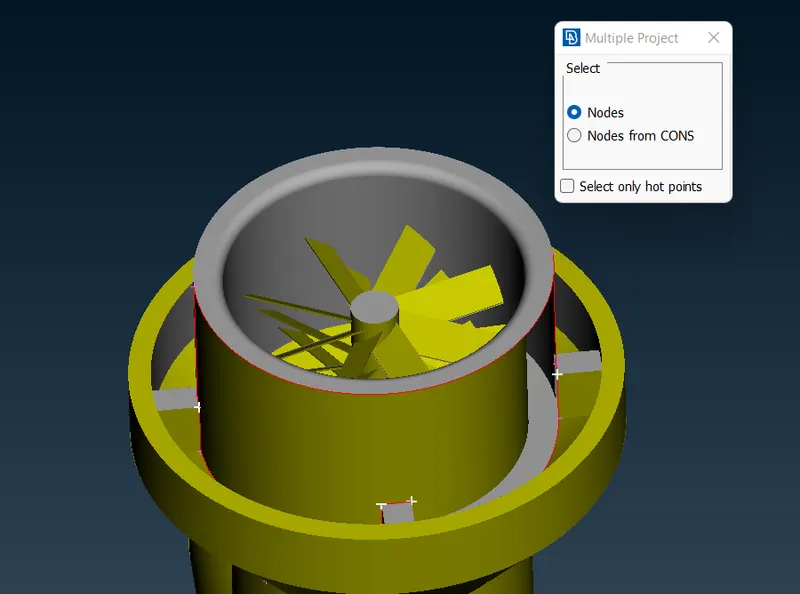
we are using multi project options to creats points on other sides
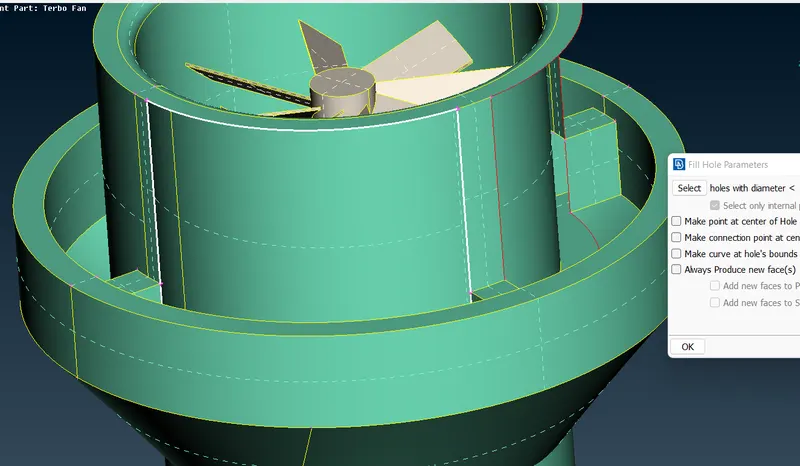
We can use fill option to fill the gap
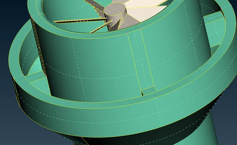
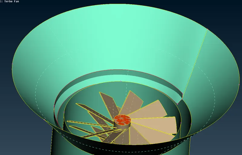
In this stage there are single cons in cone shape to clear that use should use instercest options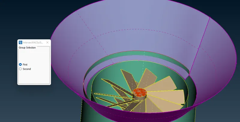
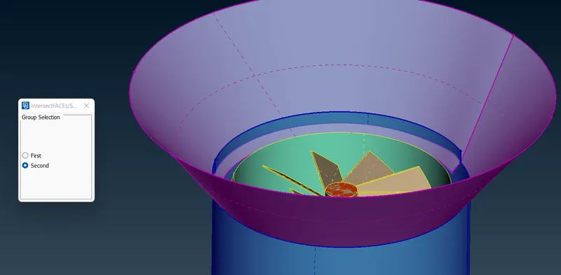
Now delete the over coming part of geometry
Also delete the overlaping surface like glitches thats the over laping
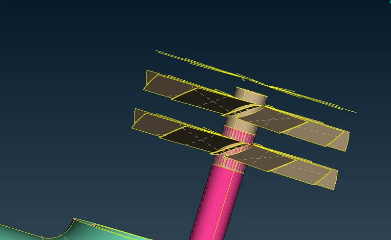
In this case we need roter blade on the brown colour it should not be on the shaft
so we can use project cons make double cons
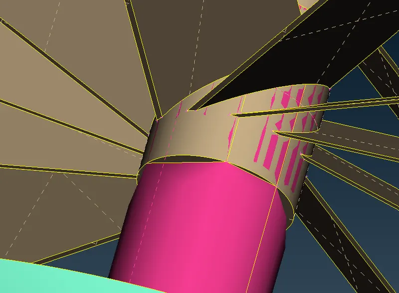
To make a circle use fine option
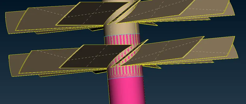
After That use relese and topo option overcome with single cons
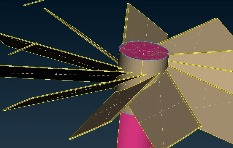
There is a overlaping surface we need to delete that to make a volumemetric mesh
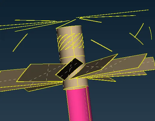
By using this steps we can solve all the overlaping and thriple cons
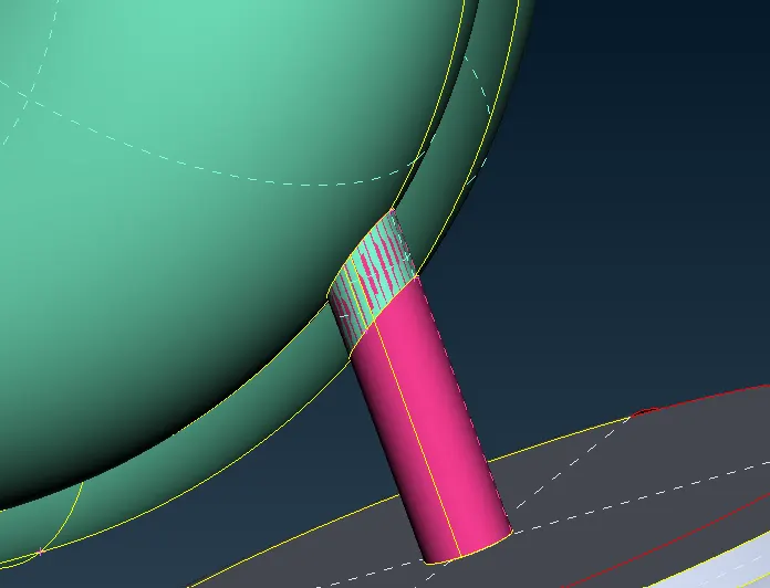
We can use same option to get rid to overlaping
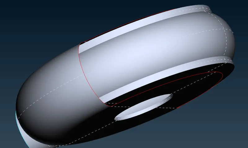
To solve this single cons error we can use parametric option
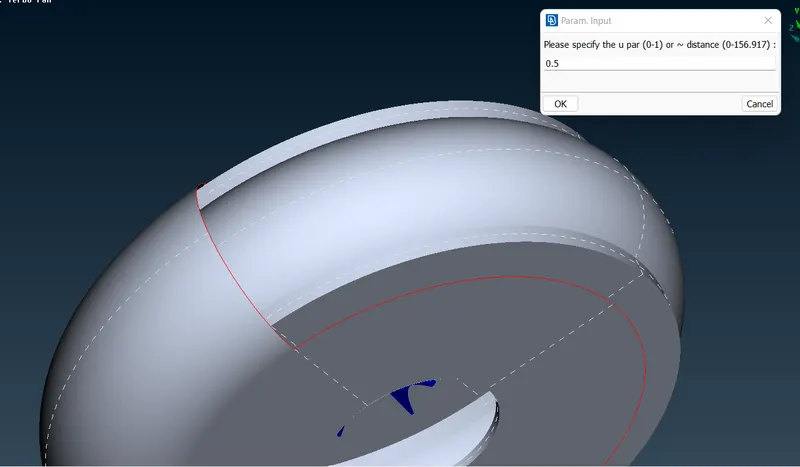
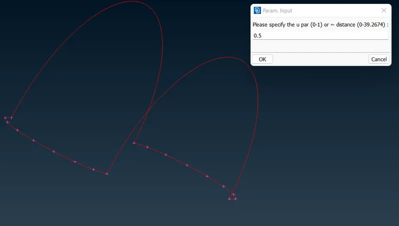
after this step use new option the fill the surface
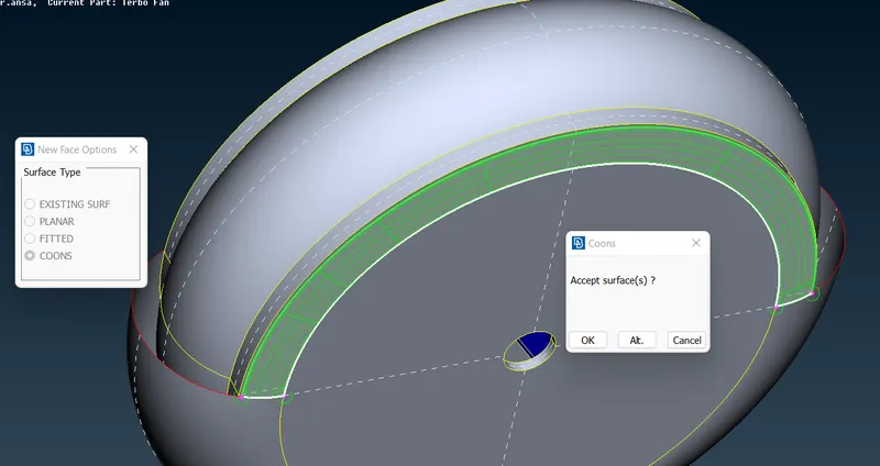
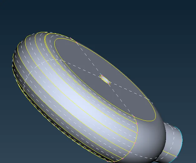
The geometry must be filled there must no gap to perform the meshing so fill the inlets an outlets of turbocherger
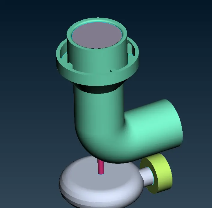

This the final clean up geometry
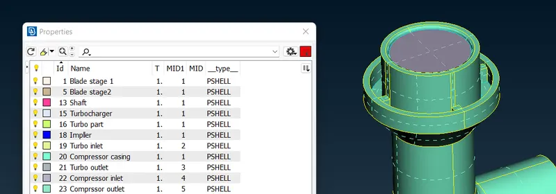
We rename the PID according to the parts
Start meshing According to the given parameters
- Blade stage-1 = 1 mm
- Blade stage-2 = 1 mm
- Impeller = 2 mm
- Shaft rotor = 1 mm
- Turbo casing = 5 mm
- Compressor casing = 5 mm
- Inlet casing cover = 5 mm
Compressor casing 5mm
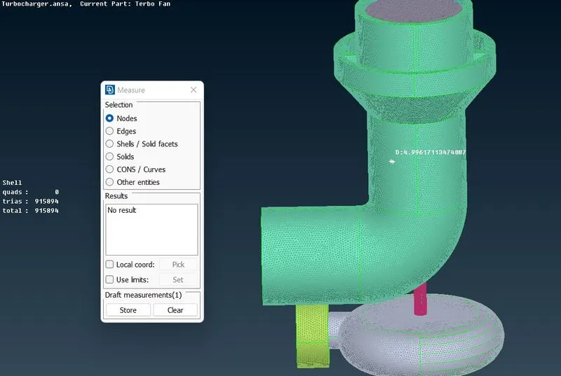
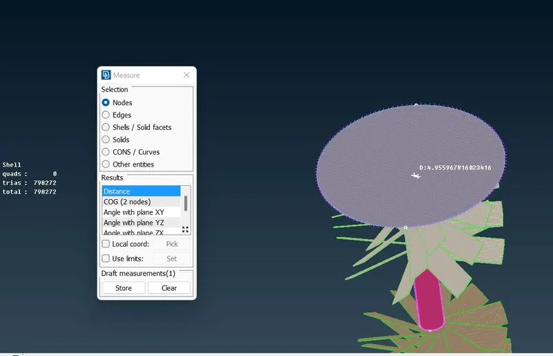
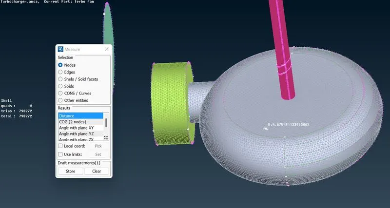
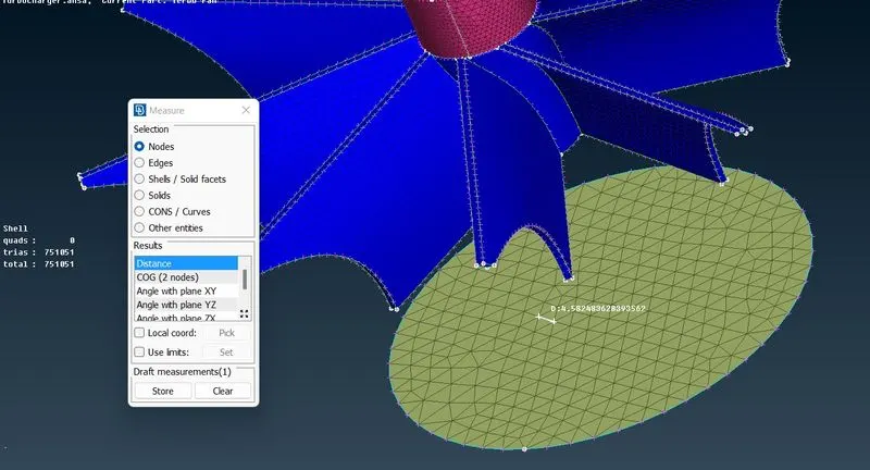
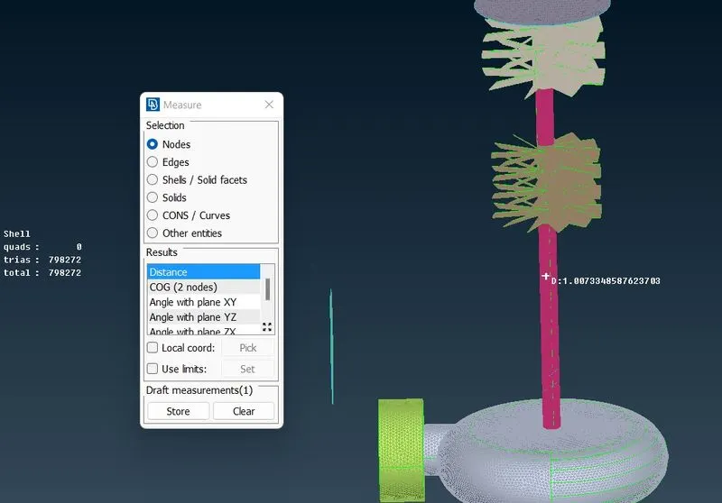
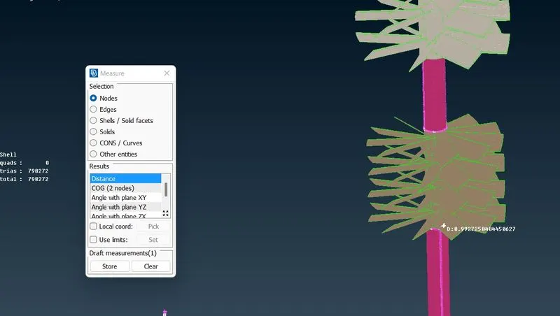
Shaft and blades 1mm
Imprellers 2mm
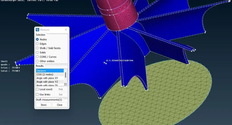
After all surface meshing then the last step Volumetric mesh
Use define and auto define to dected the volumes od the geometry
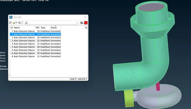
This are the volumes
selects the requried volume wich the fulid volume is flow
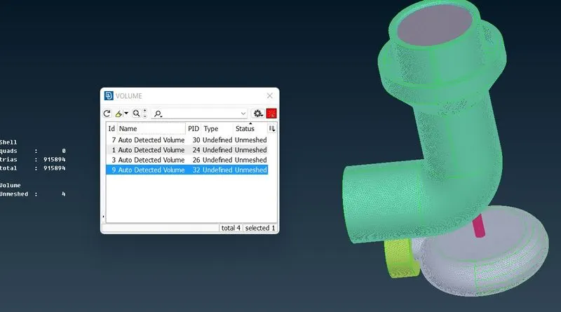
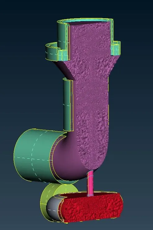
There are 4 parts which volume which fluid will flow delete the remaning parts the are not requried
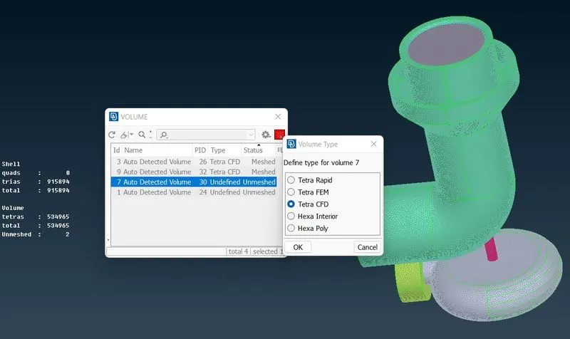
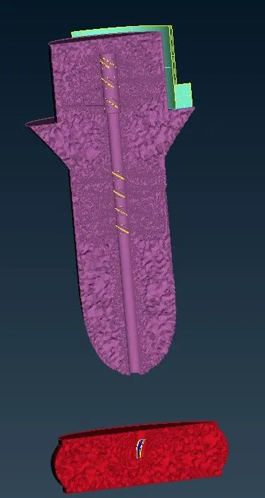
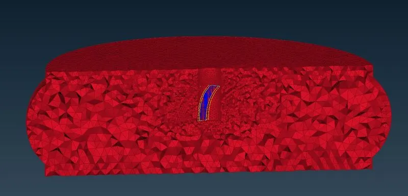
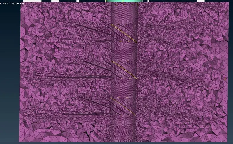
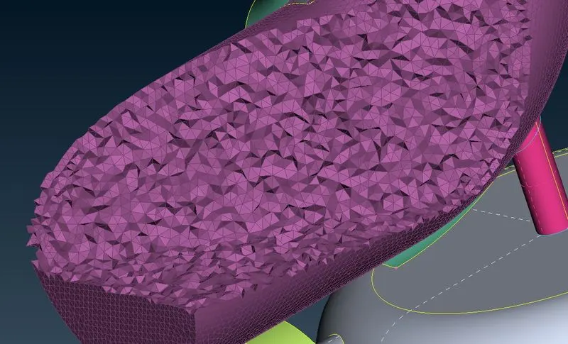
Use remesh option and tetra CFD for to get the volumetric mesh
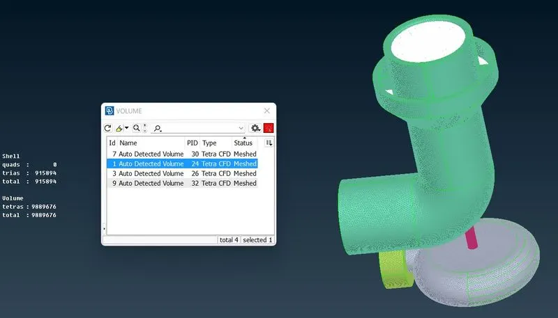
The final geometry
Conclusion:
Got familiar with more complicated and advance ANSA tools
How to solve the overlaping surfaces
Learnt about volumetric meshing along with 2D meshing.
Selection of volumes for volumetric meshing.
Creating hot points to convert complex missing parts into simple ones
(The ANSA final file of Turbocharger is not getting attactched i think because of large file its upto 577mb.)
*************************************************************************************************************