Week 3 Challenge : CFD meshing on Turbocharger
Aim: For the given model, check for the geometrical errors to make appropriate volumes. Create and assign PIDs as shown in the video.
Objective: Perform surface mesh with the given target lengths as per PIDs.
- Blade stage-1 = 1 mm
- Blade stage-2 = 1 mm
- Impeller = 2 mm
- Shaft rotor = 1 mm
- Turbo casing = 5 mm
- Compressor casing = 5 mm
- Inlet casing cover = 5 mm
Procedure:
- Surface Meshing on a given turbocharger Cad model.
Topo Cleanup->Overlapping surface found on the model and we have to delete that with Faces-> Topo->box selection ->middle click we find blue color lines on the surface that is nothing but triple cons so we have to delete unwanted surface from the model Select->Delete->PID ->select pink color surface cross hatch->delete
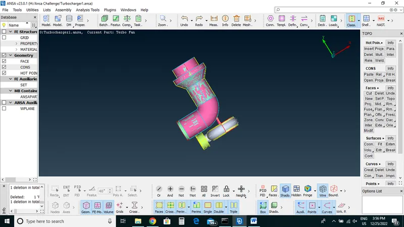
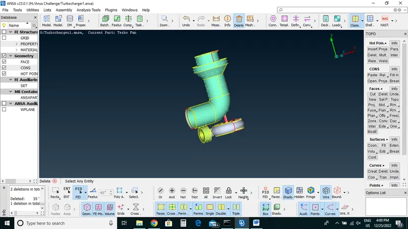
Now we delete over size surface with entity option by selecting surface then delete it.
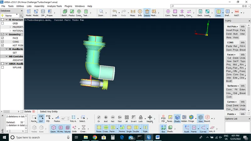
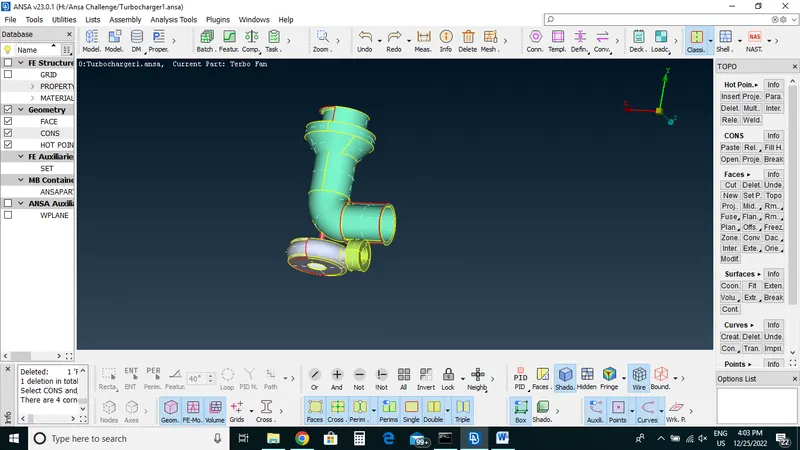
Now Create Double cons by select->Faces->New->coons->Loop->middle click
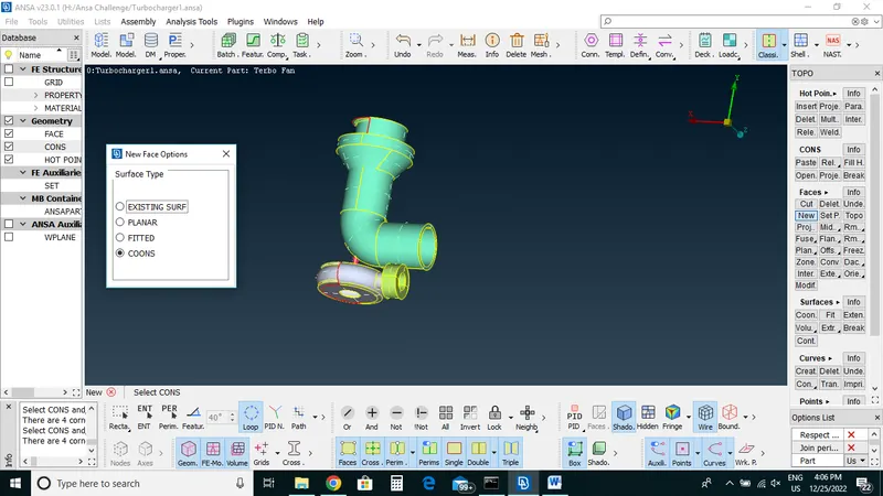
For upper side of model has complicated single cons.
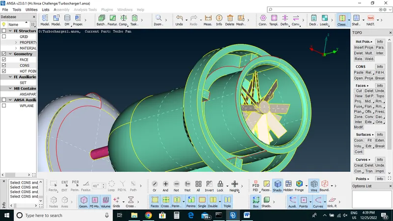
We will create new hot points and joint them and create surface with faces option.
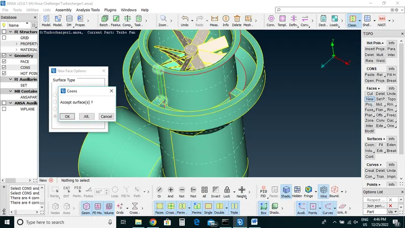
Hot points->multi points->select points->middle click->choose surface->middle click
Now we will create surface with Faces->new->Coons->selct cons with entity mode->middle click ->Preview ->ok
Now we will create surfaces one by one
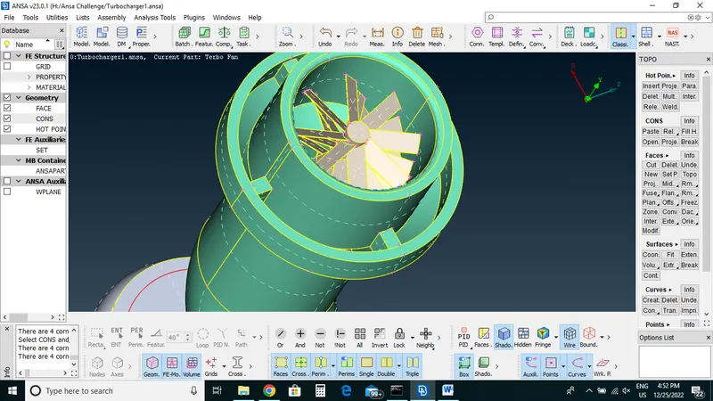
Slant surfaces at top side which is creating single cons we will Use intersection option for creating double cons
Surfaces
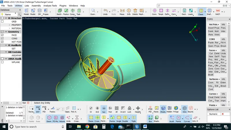
Select ->intersect->first surface and then -> second surface-Middle click
Now Triple cons are formed so now we will delete both single cons
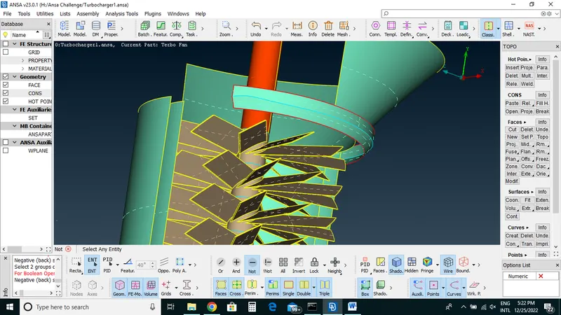
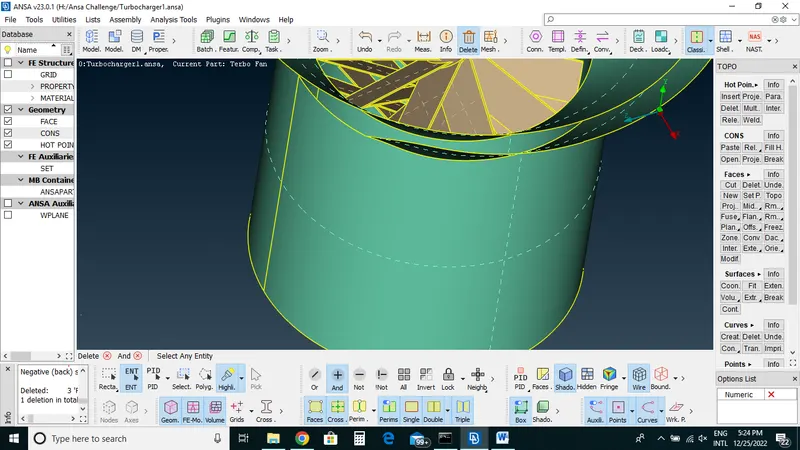
Overlapping Triple cons surfaces on top part
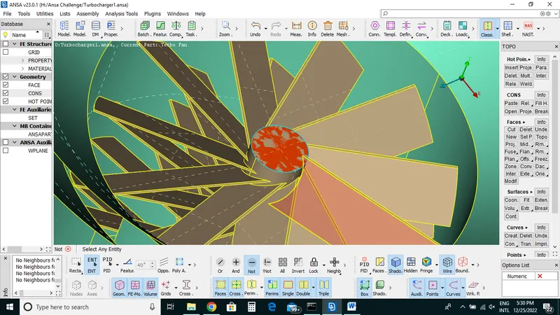
Select->Delete still triple cons is there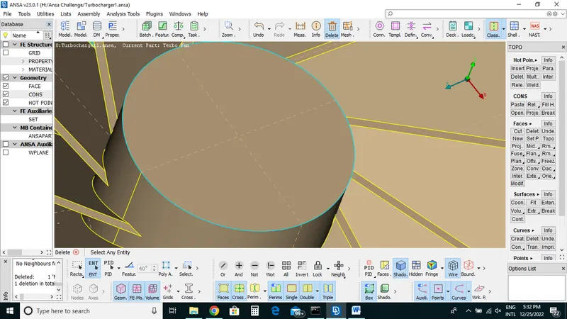
Now manually release the cons
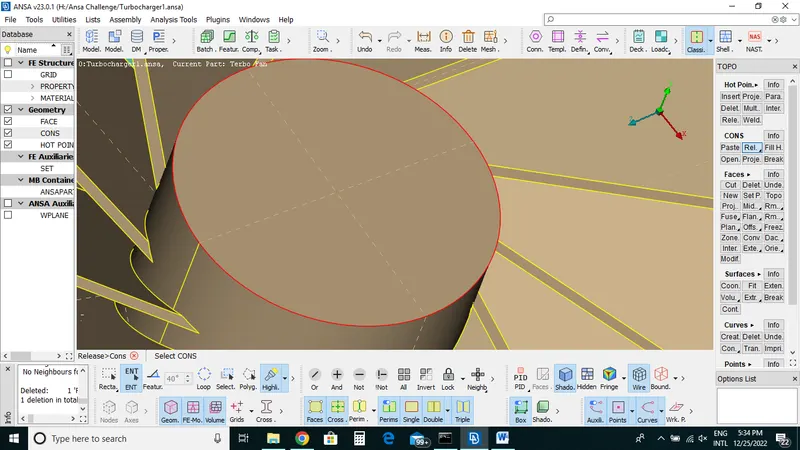
Which will form Single cons and separated with each other we will be deleted unwanted hot points
Then Topo ->Box selection ->middle click ok
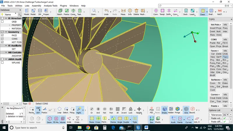
Now we will do topo to bottom side
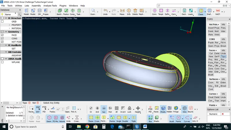
We will create small ll surfaces parametrical option 0.5
With this we will create hot points
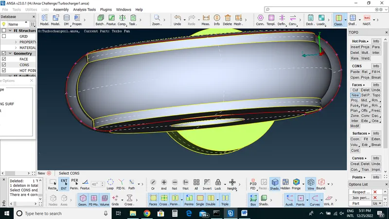
Now create surfaces with New option and create double cons one by one
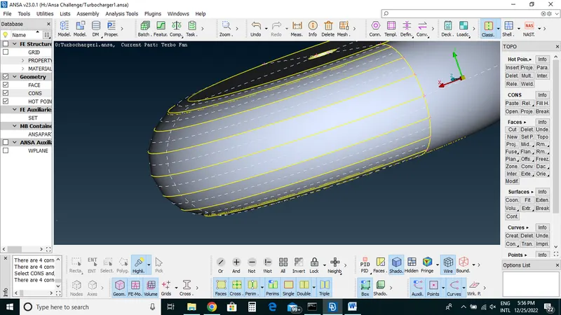
After doing Topo cleanup we will see that any single cons left for that we check with enabling double and triple cons now we will see only single cons remaining.
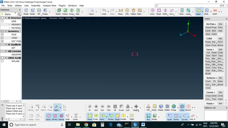
With topo we will convert it to triple cons now check with geometry check for any single cons left
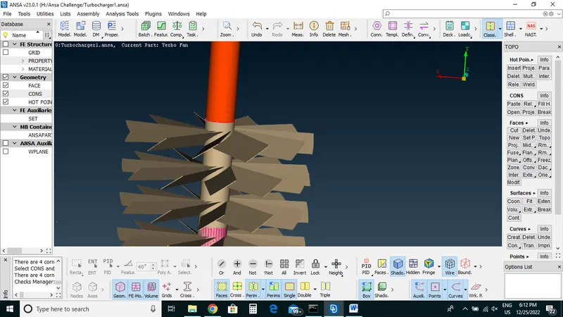
No single cons left now so that we will create triple cons that mean overlapping surface.
Now work with Triple cons on bar try to convert into double cons with deleting overlap surfaces
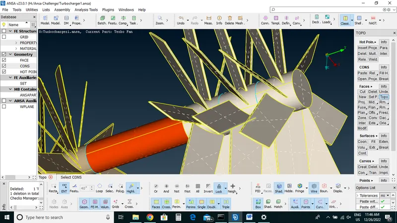
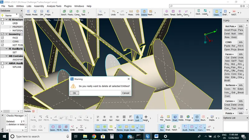
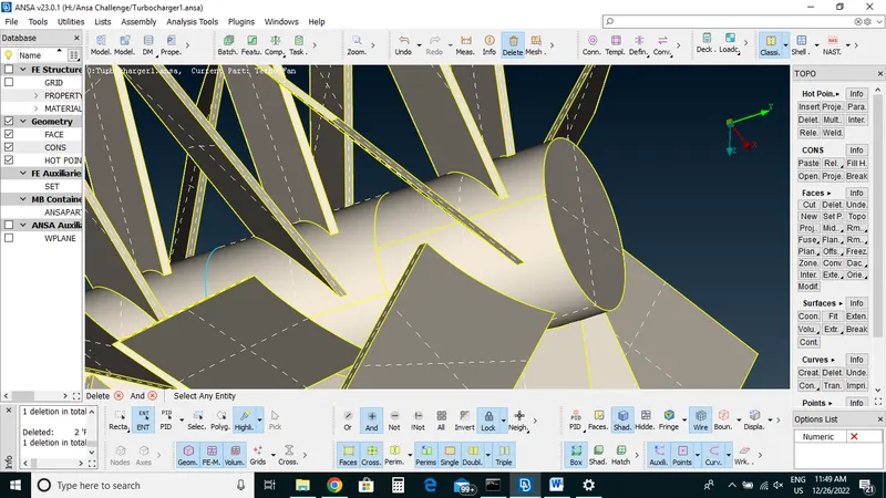
Will delete all the triple cons from the bar one by one.
After deleting overlap surfaces still triple cons exists for that we will cut shaft so that we divide shaft and then delete overlap surface.
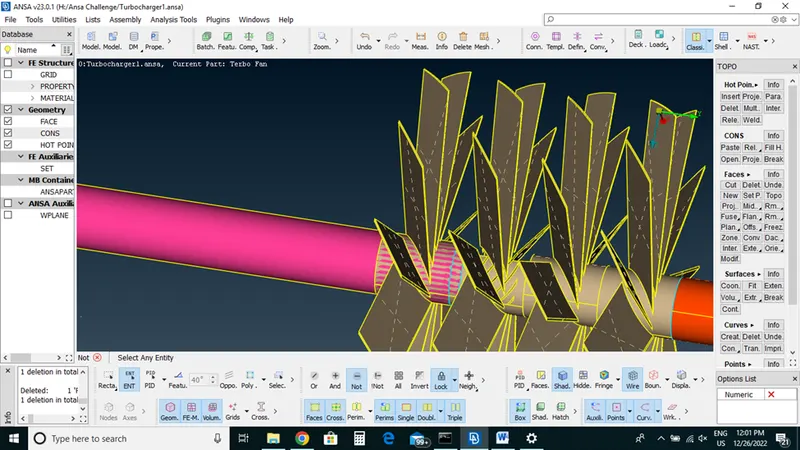
By selecting entity wise overlap surface and delete it
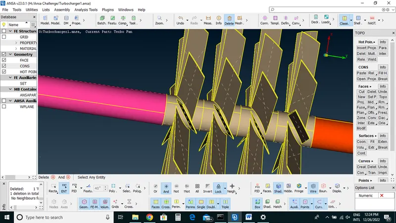
After doing this cleanup we will check geometry check for any single or triple cons left in geometry clean up
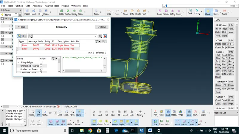
We left with only one triple cons and that triple cons id necessary we will not delete that
Now we will close our geometry
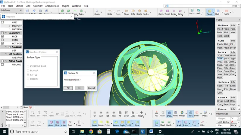
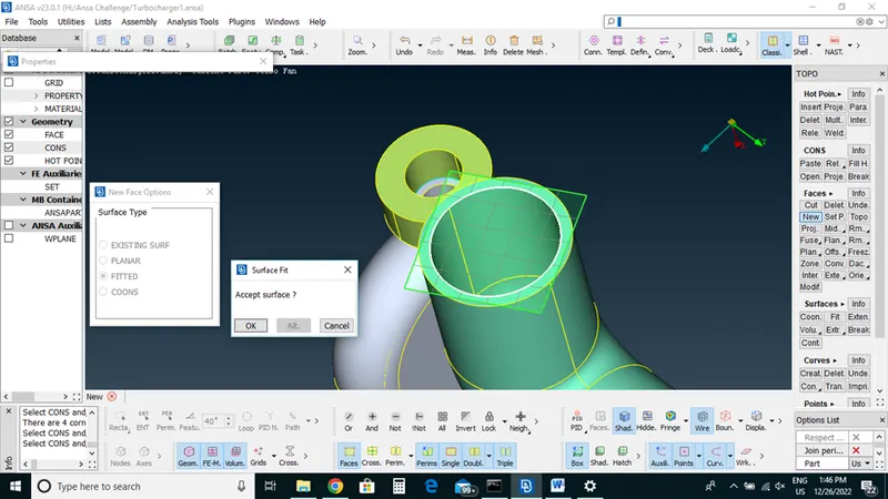
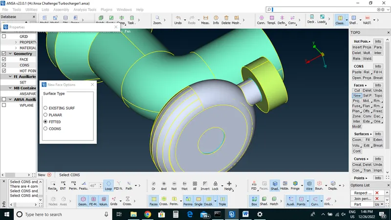
After that we will assign PID.
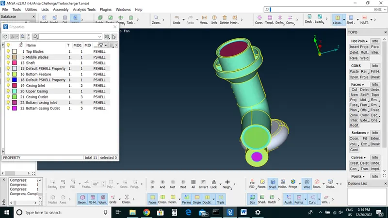
Before meshing we have to delete some overlapping surfaces which we forget to delete
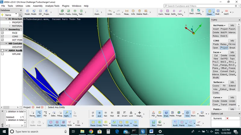
Before Going for meshing we will have to check again any single cons left in our model
If not then we will go for meshing
2.Meshing
For meshing we will go with one by one PIDs
First we will select Compressor casing ,inlet ,outlet
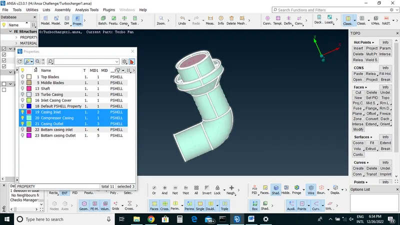
Target length 5mm and type Tria for compressor
Quality Criteria=Min 3mm and Max 7mm
Mesh Parameter Can be min 3mm and max 7mm
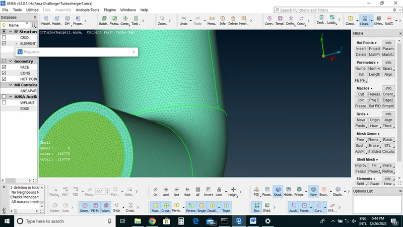
Now we select Turbo casing and inlet cover casing same time because both has 5 mm target length
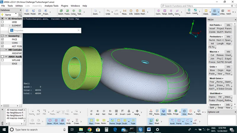
After outside meshing now we will go inner shaft to mesh
First select Impeller
Target Length=2mm
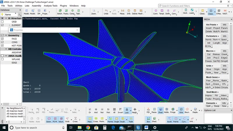
Now will mesh shaft, Blades one by one according to given mesh length
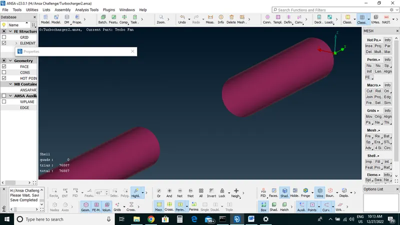
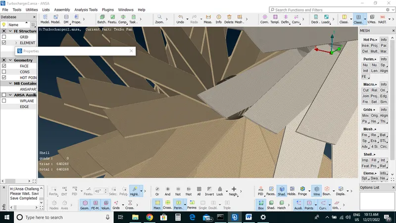
3.Volumetric mesh
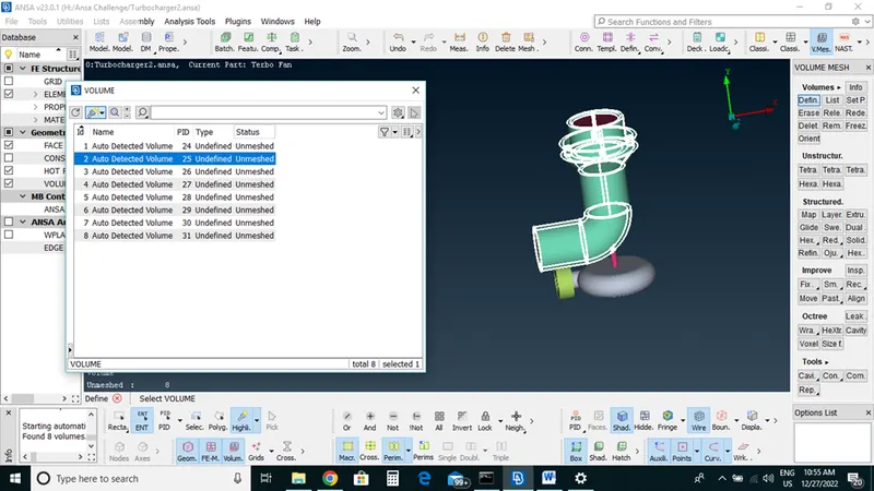
Volumetric Deck->define->long press->Auto detect->Popup comes ->select whole database it will shows auto detected volume list
Meshing this particular model for CFD application we will be mashing only which volumes which are not occupied or not taken by our parent geometry thickness.
Each and every geometry is its own thickness so that we will not volumetric mesh but we should do volumetric mesh for space inside our particular volume where fluid may flow
Basically we will be taking volume where fluid will flow and then will try to that may be 3D mesh noting but tetra mesh to that particular volume and then we will be delete rest of the volume
Now we will check which volume required and which is not required.
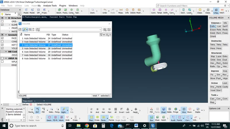
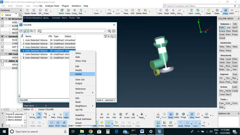
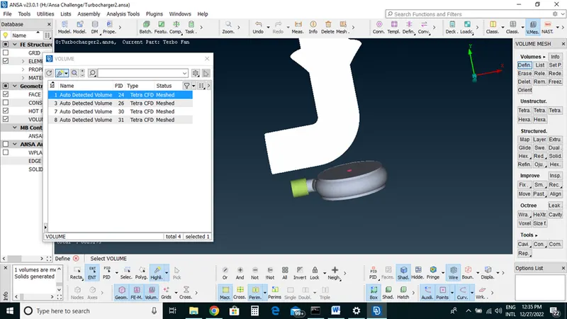
Now after deleting volumes we left with only core volumes
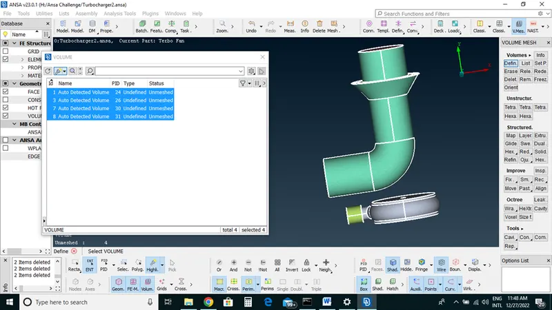
One by one we will do volumetric mesh on core volumes
Select volume ->right click -> Remesh->tetra cfd
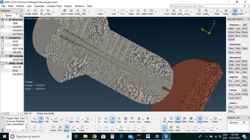
Learning Outcomes: With Ansa we can successfully do Geometry clean up , Surface mesh and Volumetric mesh on a cad model. So That we can perform CFD analysis on cad Model,
Result: In a volumetric mesh elements converted from 2D Tria elements into 3D elements which is Tetra elements.
Conclusion:With the help of Topo deck, Mesh deck and Volumetric mesh deck we perform required task on raw cad and converted into 3D model which we required for CFD analysis