Week 3 Challenge : CFD meshing on Turbocharger
Aim : For the given model, check for the geometrical errors to make appropriate volumes. Create and assign PIDs as shown in the video. Perform surface mesh with the given target lengths as per PIDs.
- Blade stage-1 = 1 mm
- Blade stage-2 = 1 mm
- Impeller = 2 mm
- Shaft rotor = 1 mm
- Turbo casing = 5 mm
- Compressor casing = 5 mm
- Inlet casing cover = 5 mm
There is a some steps to do meshing in this challenge.
Step 1 : Analyse or Refine the geometry
Step 2 : Surface Meshing
Step 3 : Volumetric meshing
First i will go for geometry analysis and refine and rectify the errors in geometry.
Step 1 : Analyse or Refine the geometry
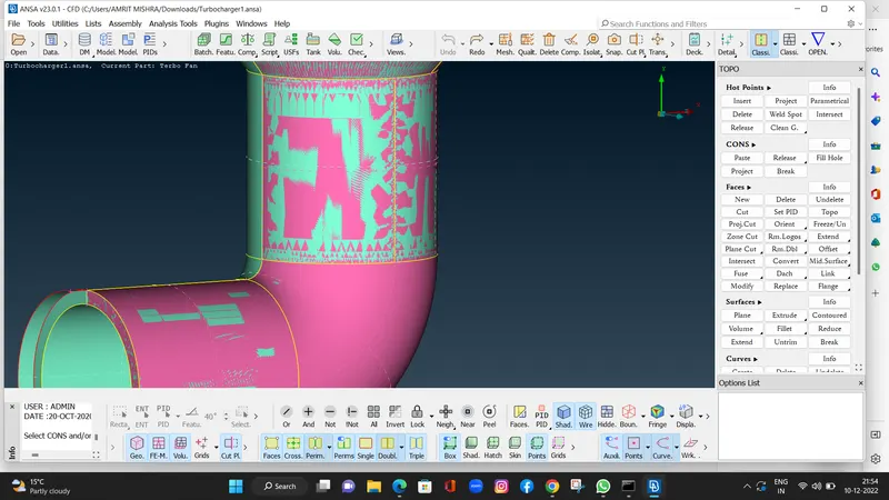
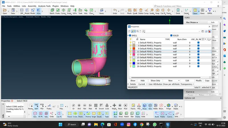
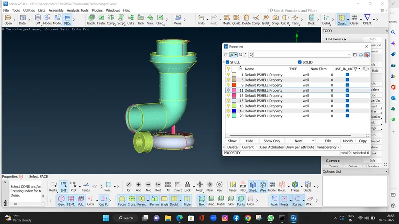
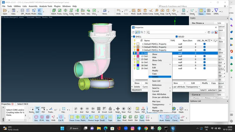
- we go in PIDS when i off the pid "11 default PSHELL Property", glitches goes disappear so i have to delete it.
- After delete pid glitches are gone.
-
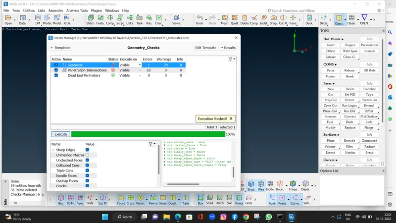
- Now we go will go for geometry check.
- There is showing 29 warings and 10 intersection errors.
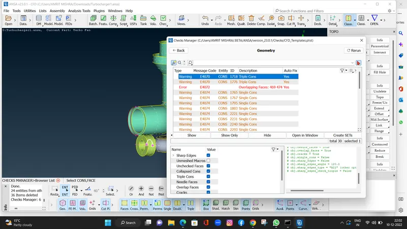
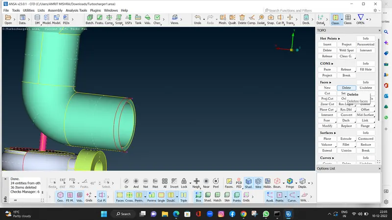
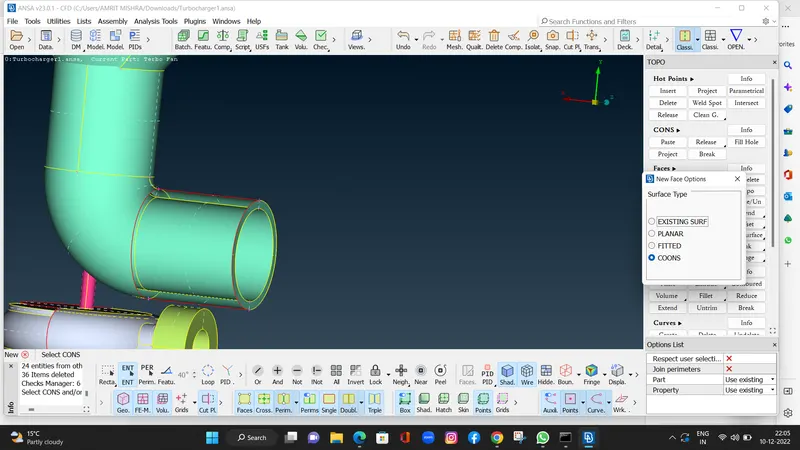
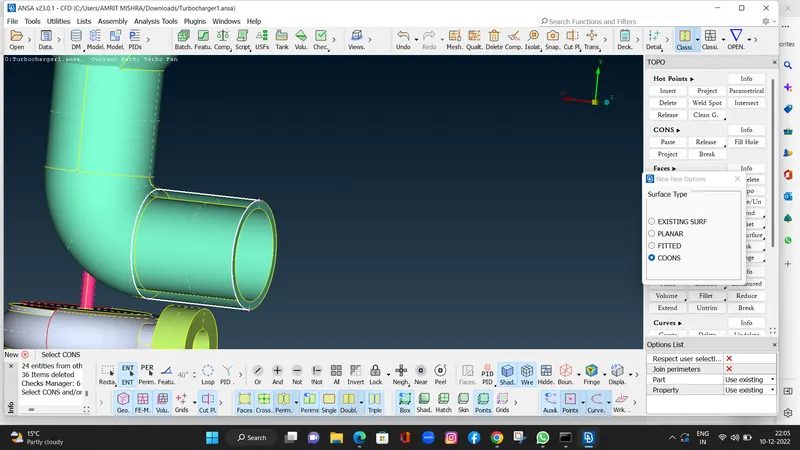
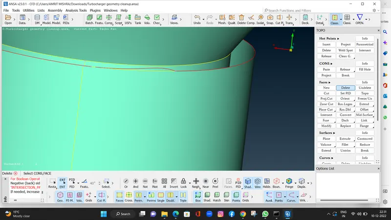
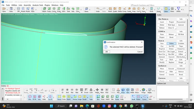
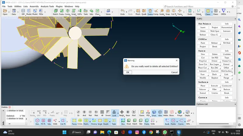
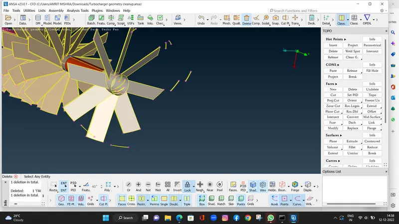
- There is extra cons , so I have to clear it, delete this extra face.
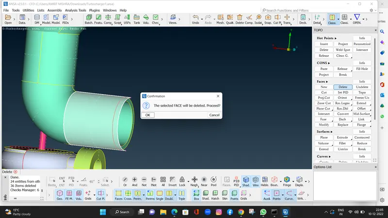
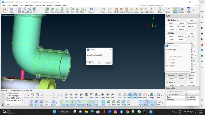
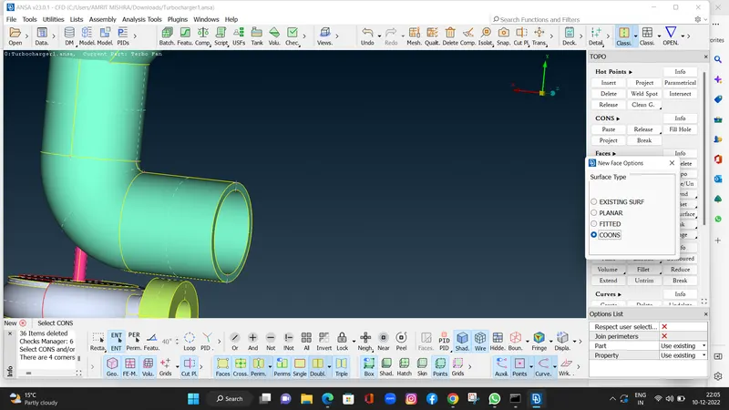
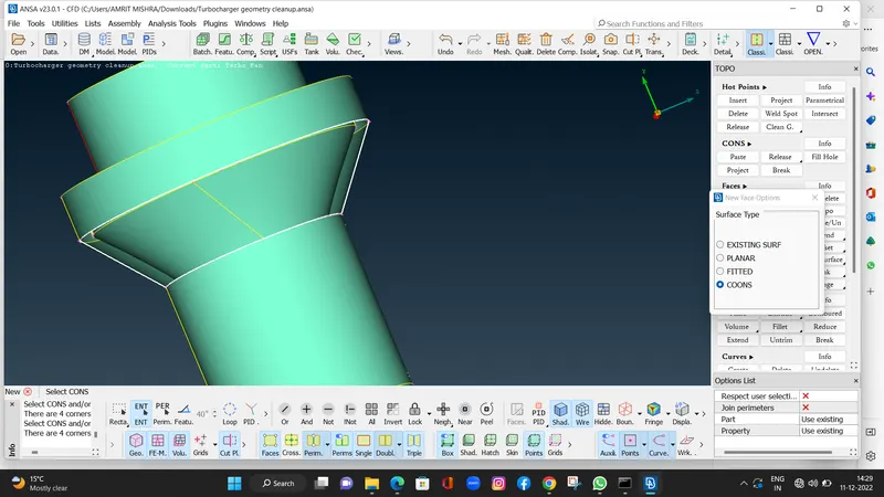
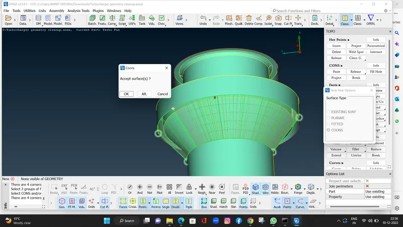
- First we have to delete the entire face and then regenerate the face by coons command.
Faces > delete >select the surface > middle click > ok .
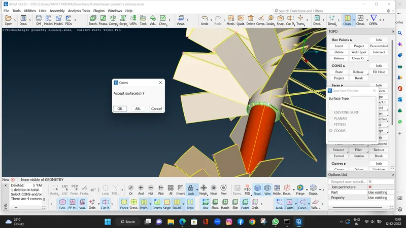
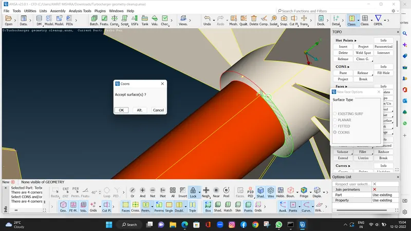
Faces > new > coons > select the the cons > middle click > ok .
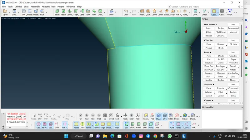
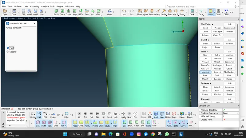
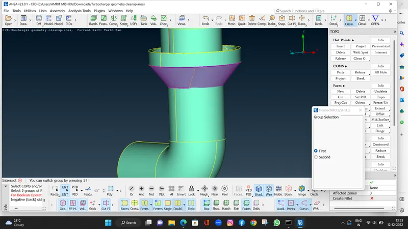
- In this geometrical error there is intersect in between tubro casing so using intersection command we will solve the error.
- First select intersect command and select the the upper two faces of the component and do middle click.
- And then select second faces of casing and middle click it will ask for delete and keep the face .
- Here we will delete the unwanted intersection face .
- And then we have to create proper boundary.
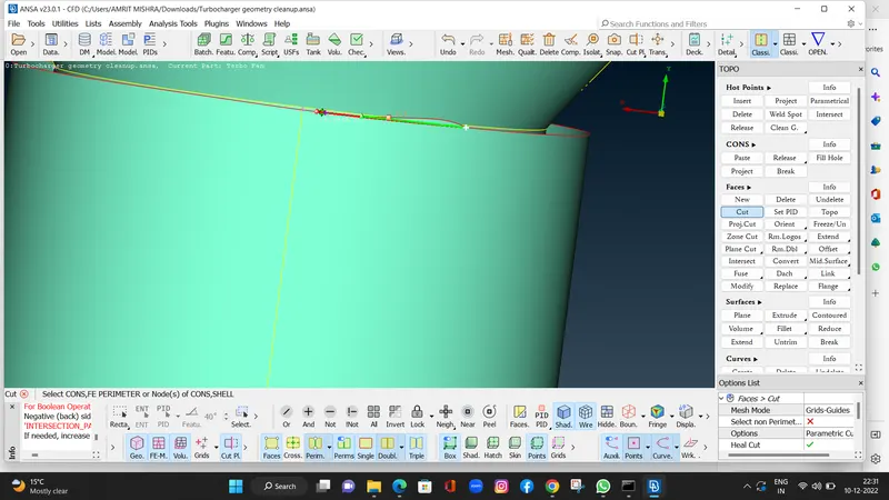
- Here using CUT command , reduce the extra faces from boundary and then delete the faces.
- And then using coons option we will create a faces on both sides.
FACES > INTERSECT >SELECT FIRST FACES > MIDDLE CLICK > SELECT SECOND FACE > MIDDLE CLICK > DELETE OR KEEP .
FACES > COONS > SELECT CONS > MIDDLE CLICK > OK .
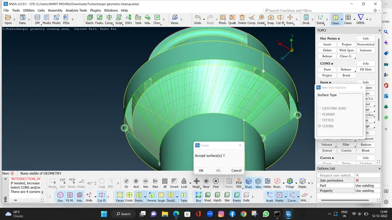
- In this there is face missing so we will rectify the error.
- In easy way we have Transforms command so we will use this and create new cons.
- First we select the Transforms command and then it will ask for select cons or curves .
- selected the curve and it will ask for the direction so I selec the top two hot points and middle click.
- Same like this we will do other side .
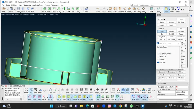
- Atfer this we will create face by using coons command.
- Then both bellow transformed curved will be created by using coons command.
- And at the end in curves we will delete the the curves we created.
CURVES > TRANSFORMS > SELECT CONS > MIDDLE CLICK >SELECT UPPER TWO HOT POINTS > MIDDLE CLICK .
FACES > COONS > SELECT CONS > MIDDLE CLICK > OK
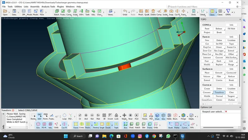
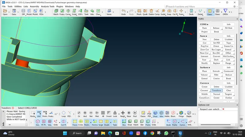
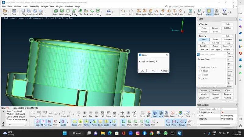
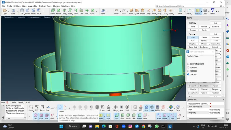
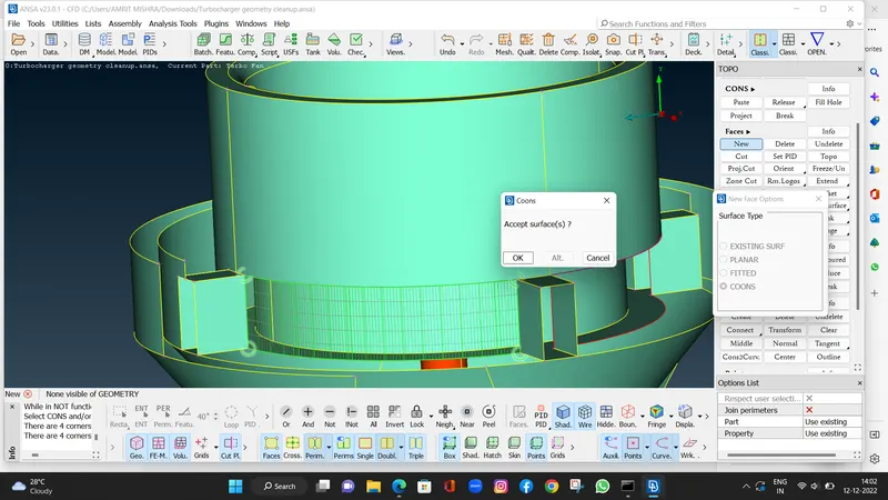
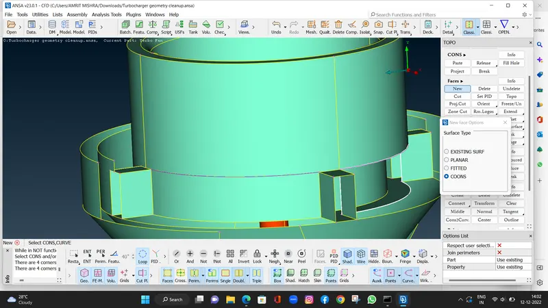
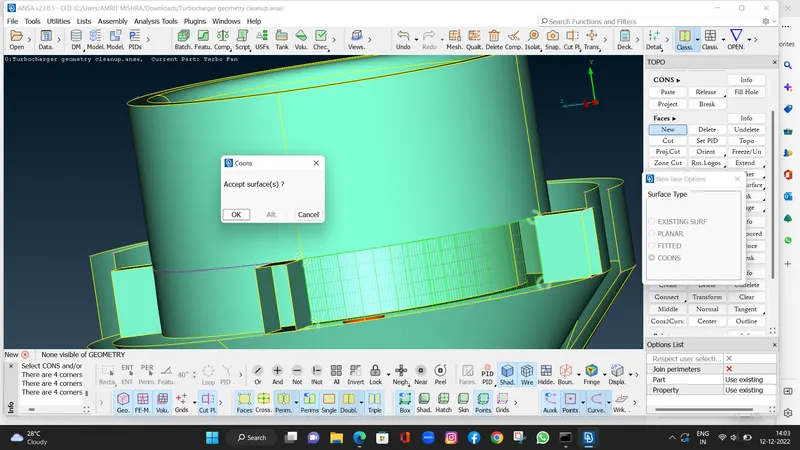
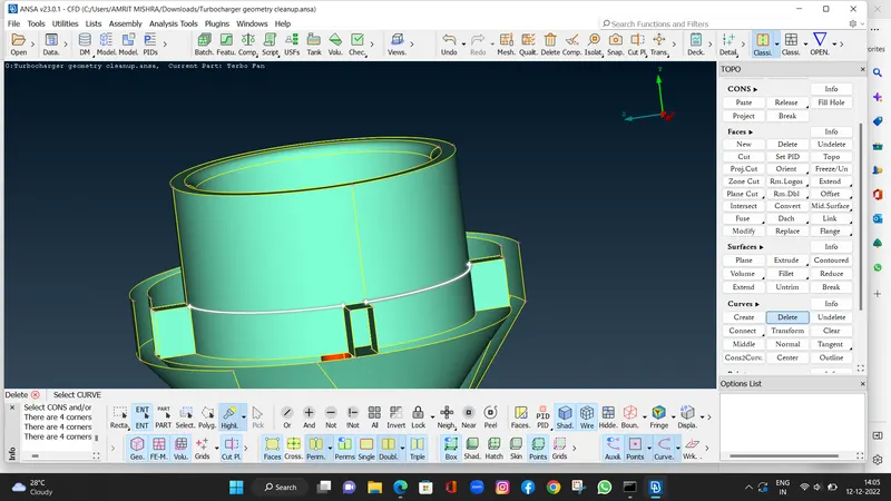
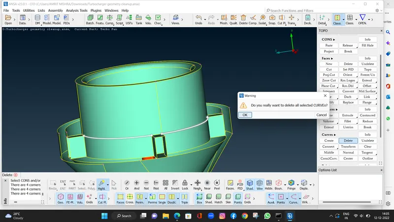
- In this there is red cons is showing .
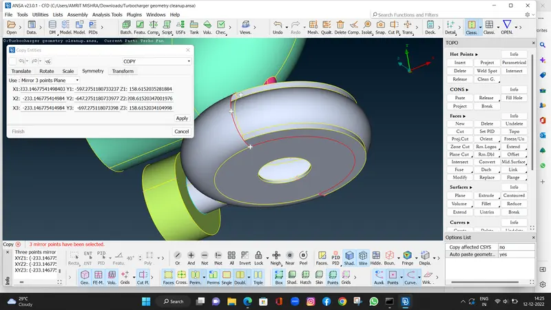
- In this first we use "Transform" command select copy command and then use entities for selection of one by one.
- Before that we have to create new hot points at the middle of the coons at both sides.
- Then select the hot points of one side and by selecting symmetry.
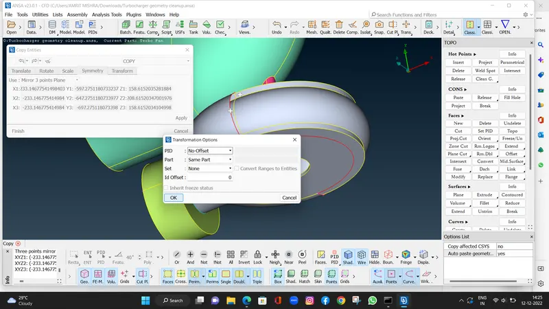
- After that drop down list is showing for the transformations option and click ok.
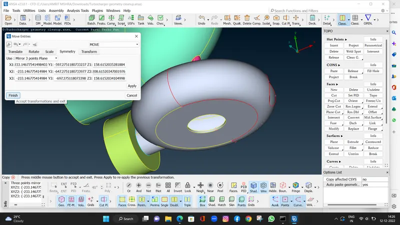
- Then click on finish.
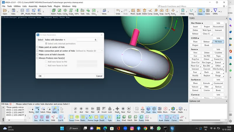
- After copy the cons there is hole of inlet so i have to fill it.
- Using Cons command select fill hole and select cons and middle click.
TRANSFORM > COPY > ENTITIES > SELECT CONS > COPY ENTITIES > SELECT SYMMETRY > SELECT HOT POINTS > OK > FINISH .
CONS > FILL HOLE > SELECT CONS > MIDDLE CLICK .
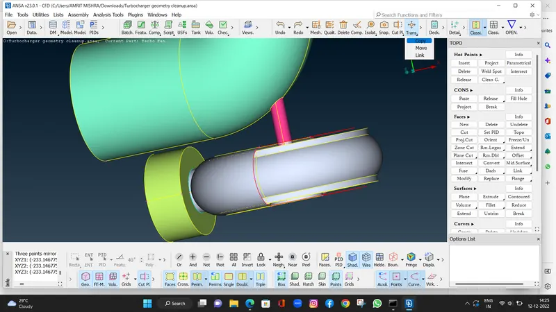
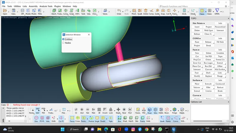
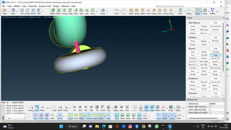
- In this first we hit TOPO Command, so here all not joint cons are joined and showing tripple cons.
- So here we have to clear tripple cons. Basically we have to delete faces of the shaft and also blade 1 and blade 2.
- Actually we have to make it on volume so we have to clear tripple cons here.
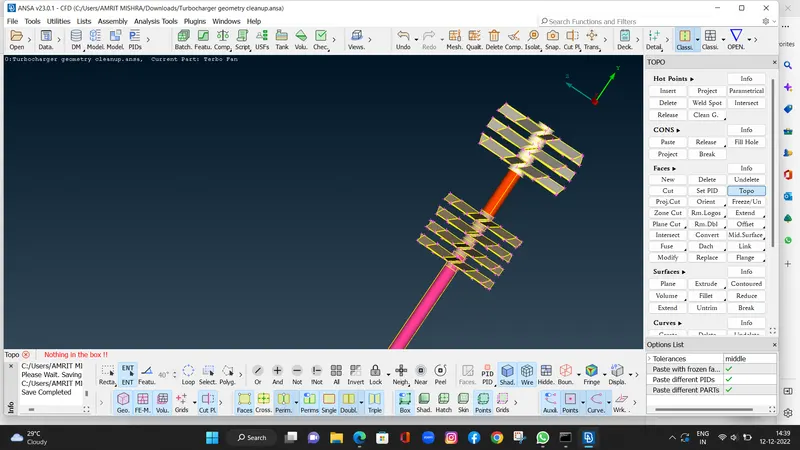
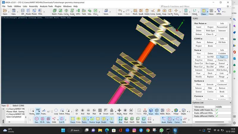
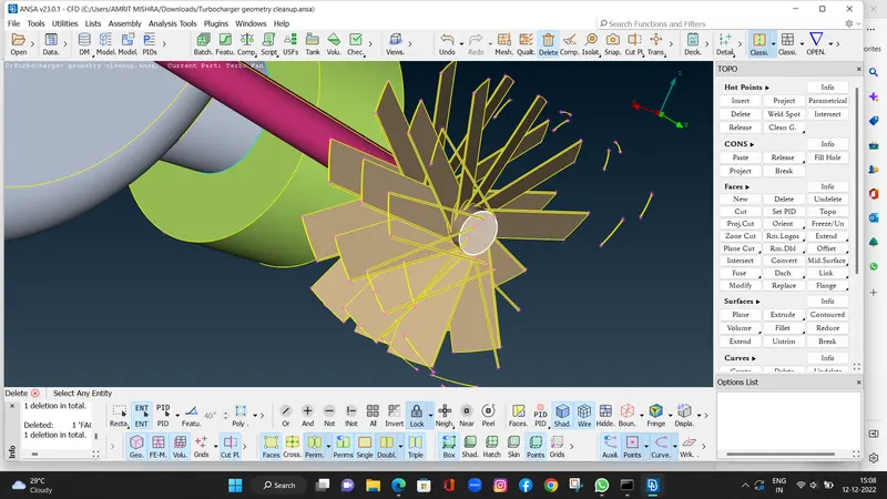
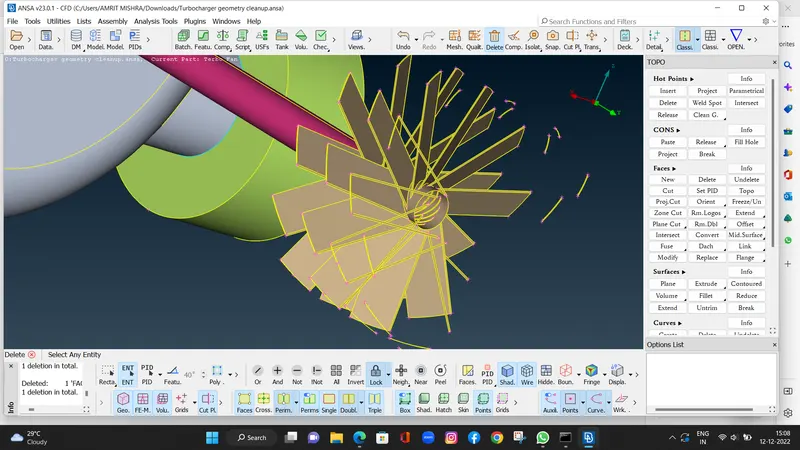
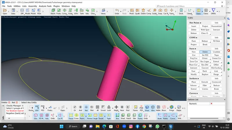
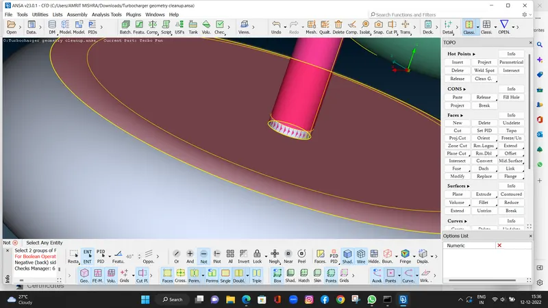
- Here is intersection errors there is two components is overlapping.
- So we have to make cut section and delete the extra part of the shaft which is going inside blade 2.
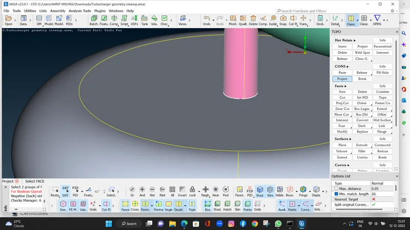
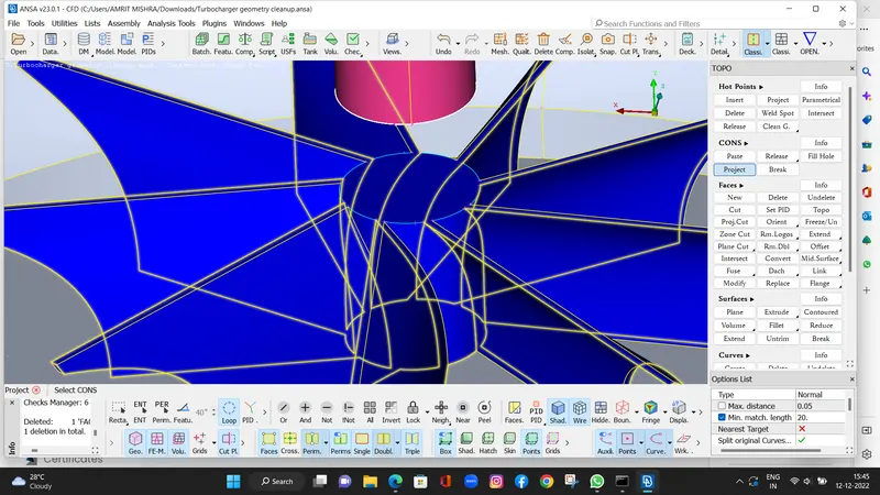
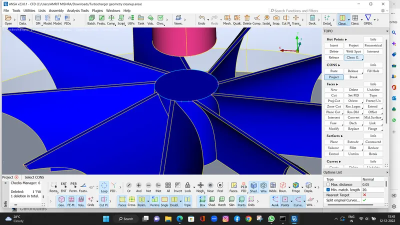
- Here i use Project command for the cut section and project the shaft in two part for deleting it.
- Under cons command there is "project" option , and select cons and then faces where we will do projecthe cons.
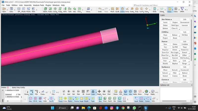
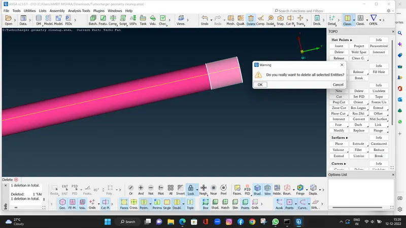
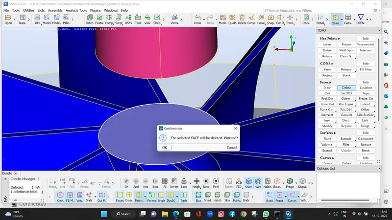
- And after that we can delete the extra shaft which is going inside the blade 2.
cons > project > select cons by entity mode > select the faces > middle click .
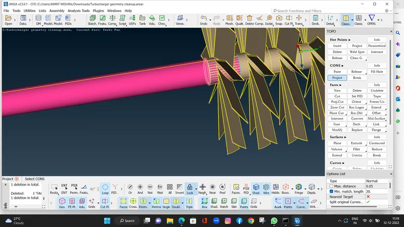
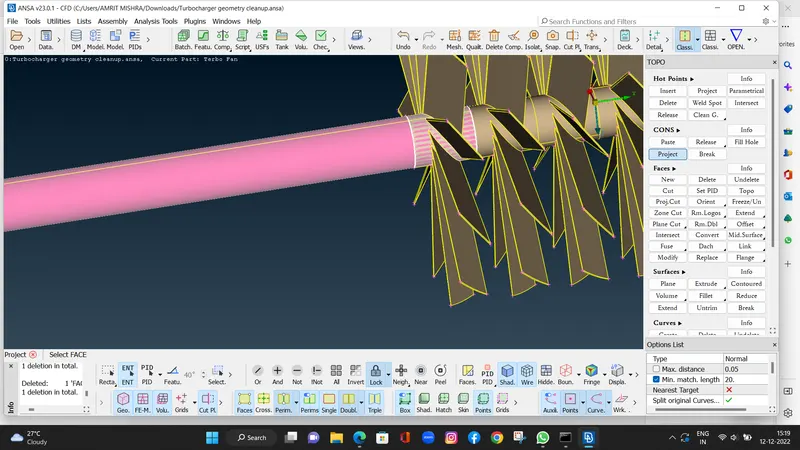
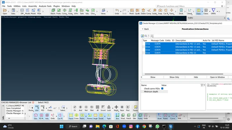
- Here we will check the geometry, There at impeller and turbocasing showing intersection errors.
- Intersection error is showing because shaft is going inside the turbo casing and impeller casing.
- And there is also showing overlapping at the shaft at both side.
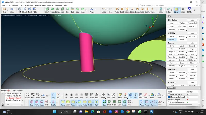
- Using project command we have to project coons and then we will delete it because shaft is going inside the turbo casing.
- And its showing errors as tripple cons.
- And there is intersected part in shaft we will clear it by deleting it.
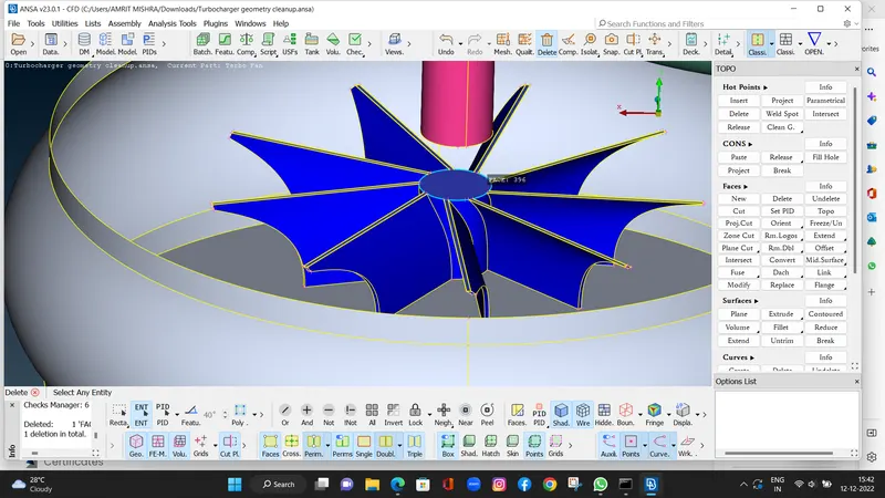
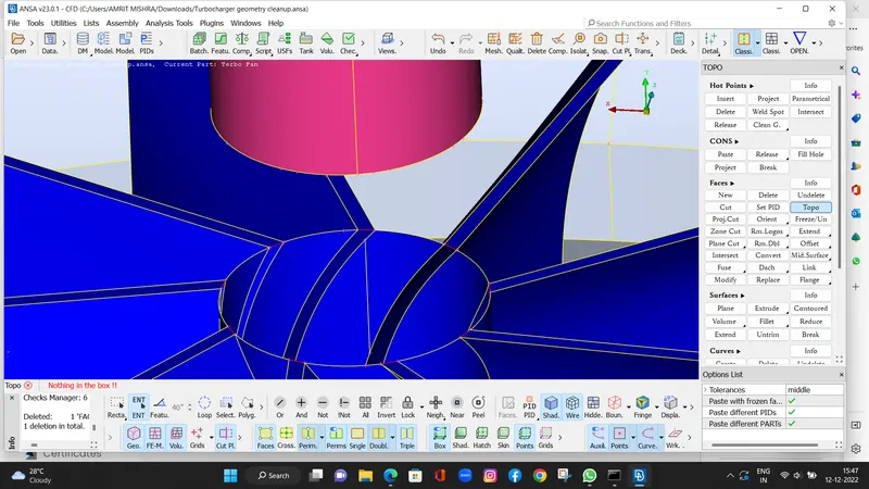
- After finishing we will do TOPO for all Impeller components,
- Doing this we can joined all unjoined cons and we dont have any errors in the geometry.
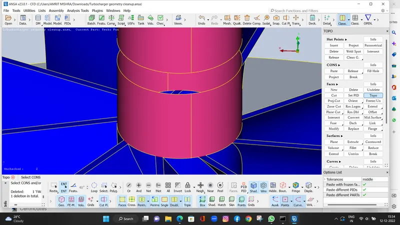
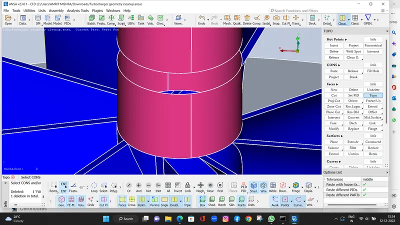
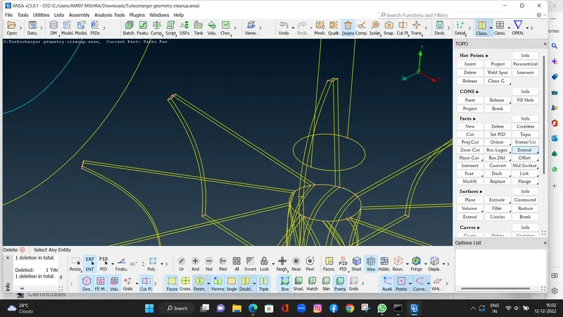
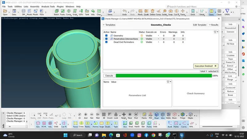
- Here we check geometry once again and there is showing only tripple cons are showing and this is avoidable, we can avoid this.
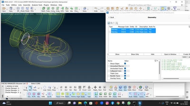
- Assigning PIDS
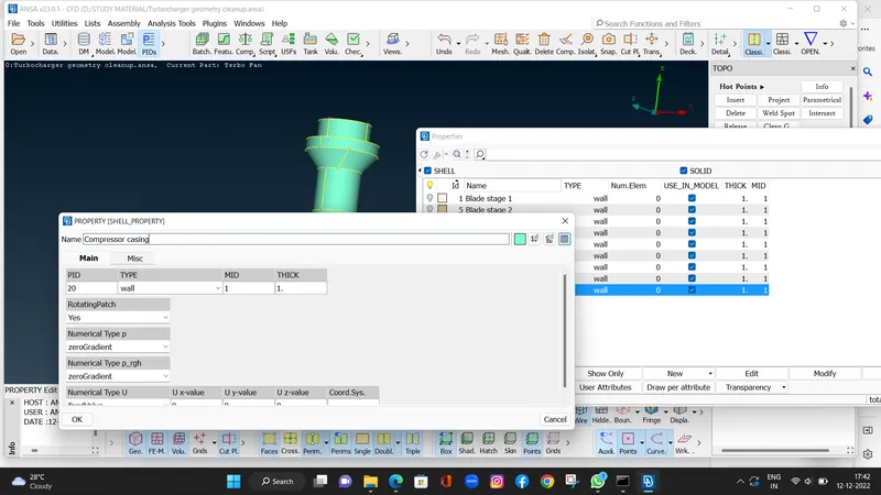
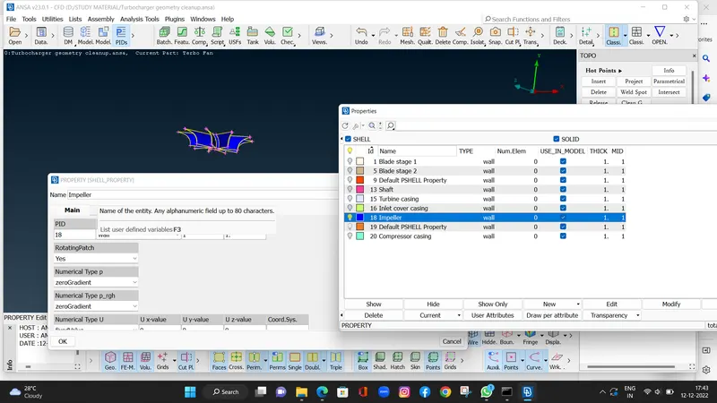
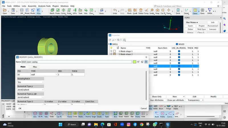
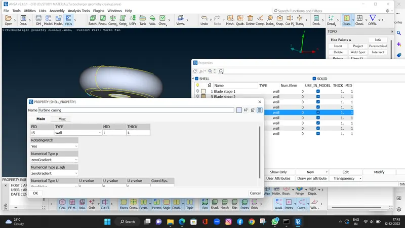
- Here we are assigning PIDS first of all we have allready assigned PIDS here just i have to changed the name of PIDS as per component names.
PIDS > double click on names of PIDS > edit the name > ok.
As we have assigned name for our geometry.
- Blade stage-1
- Blade stage-2
- Impeller
- Shaft rotor
- Turbo casing
- Compressor casing
- Inlet casing cover
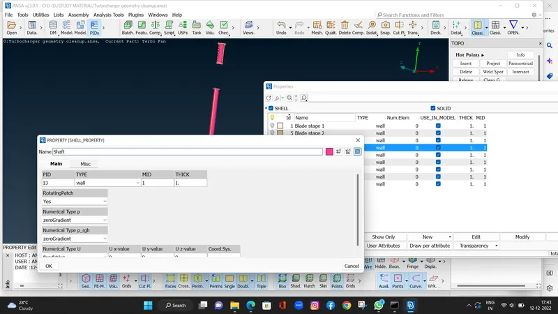
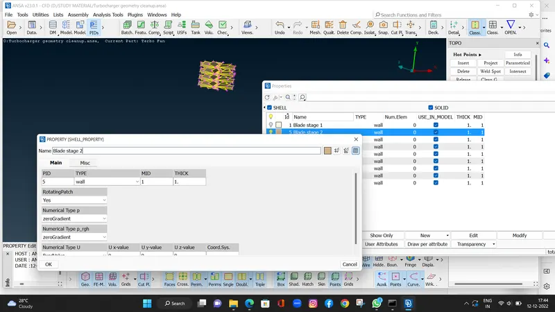
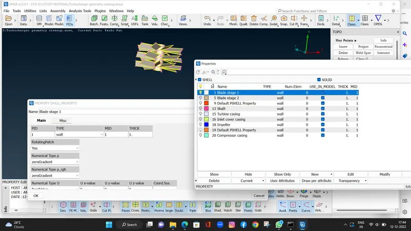
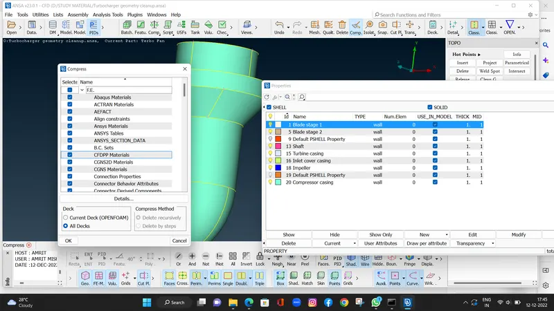
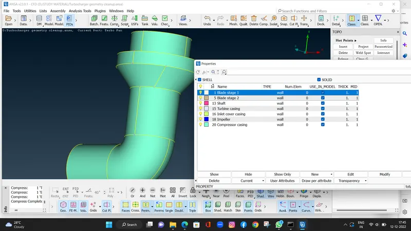
- Here we have to close the volume for meshing.
There is some opening at inlet , turbo casing , impeller casing.
we will use planner command and close the all openings.
faces > planner > select the cons > middle click > ok .
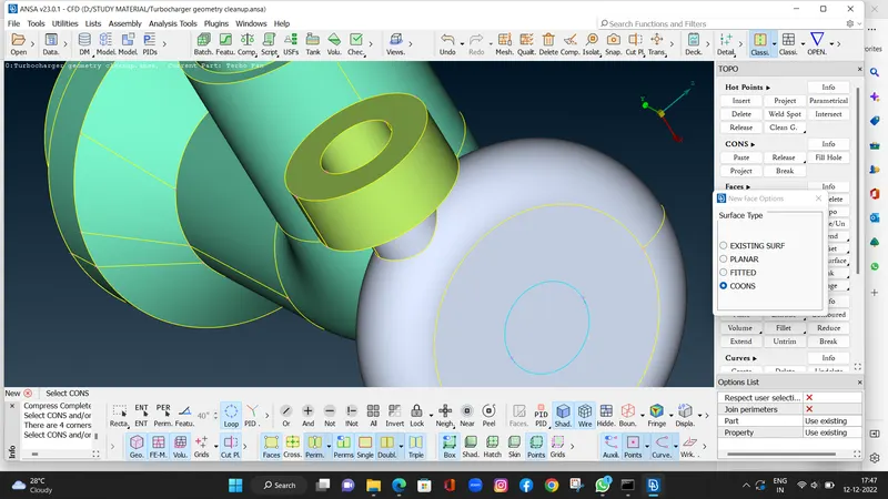
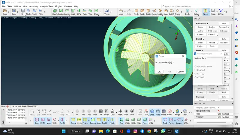
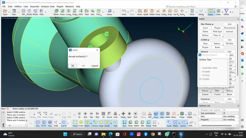
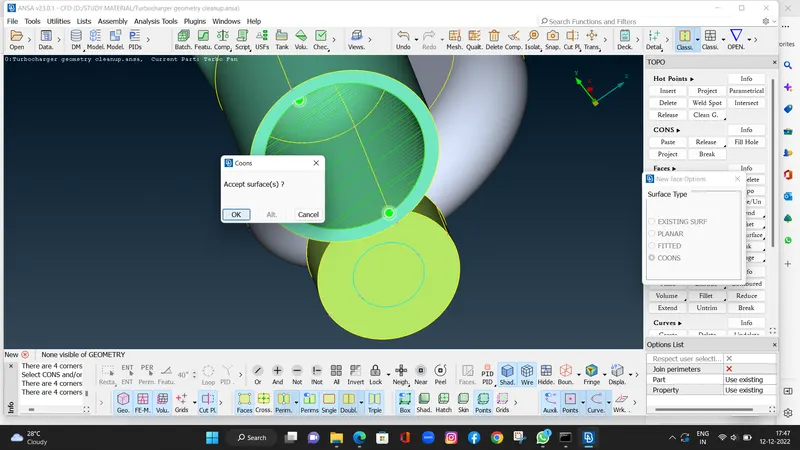
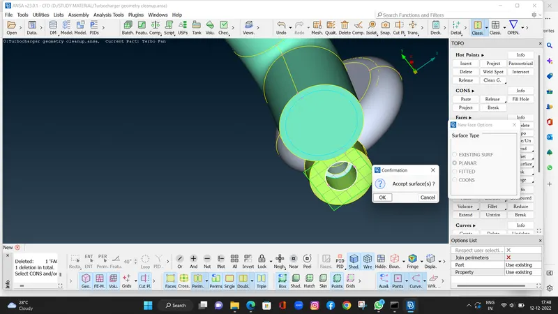
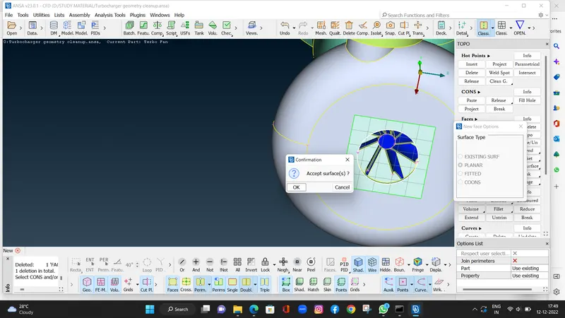
- Here some openings at turbo casing , so we use coons command and clear it .
FACES > COONS >SELECT CONS > MIDDLE CLICK > OK .
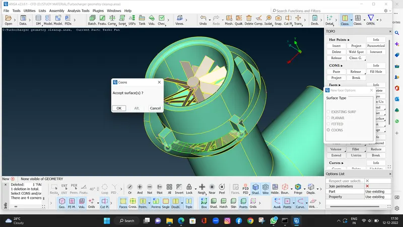
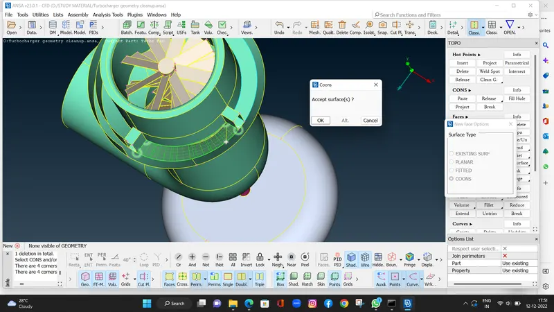
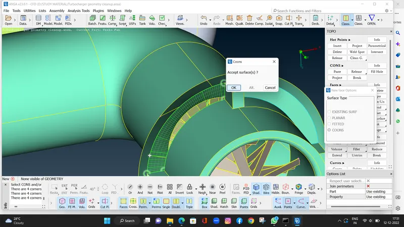
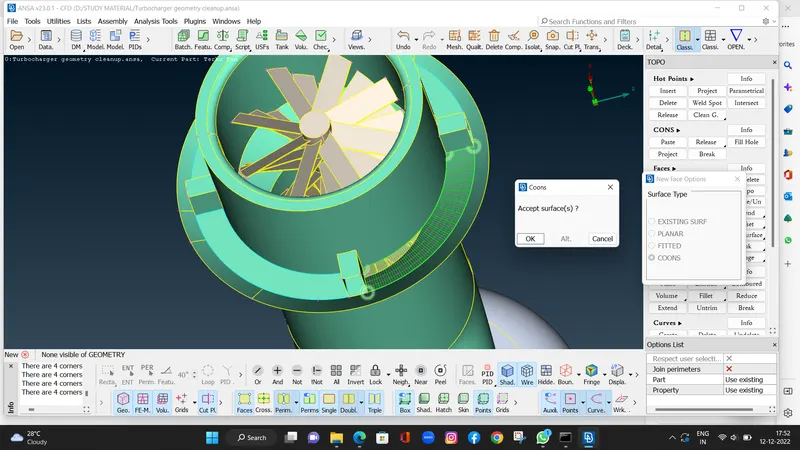
- Here we will again check the geometry for the all errors but there is no errors only tripple cons are showing in the impeller section , we can avoid that tripple cons.
Step 3 : Surface meshing
So accoring to the meshing conditions there is 1 mm target length is for blade-1 , blade-2 and shaft .
we will go to PIDS and off all the Assigned PIDS except those three components.
Then in perimeters using spacing command select paerimeter and select the entire part and as well as macros then do middle click.
After that we will go for Mesh generation in CFD and CFD VISIBLE command.
PERIMETER > SPACING > AUTO CFD > PERIMETER > SELECT GEOMETRY > MACROS > SELECT GEOMETRY > MIDDLE CLICK.
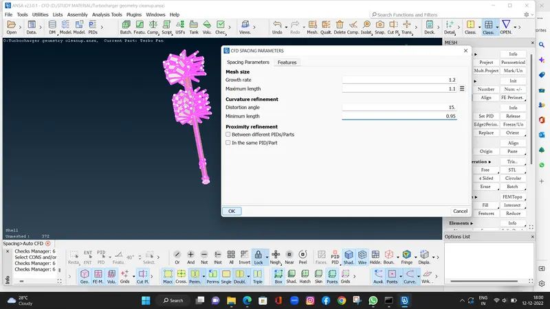
- Before go for mesh generation in spacing auto cfd it will ask maximun and minimum target length so we have 1 mm target length.
- Here I took maximum length 1.1 mm and minimum length 0.95 mm, then click ok.
- Now I can go for mesh generation.
MESH GENERATION > CFD > VISIBLE
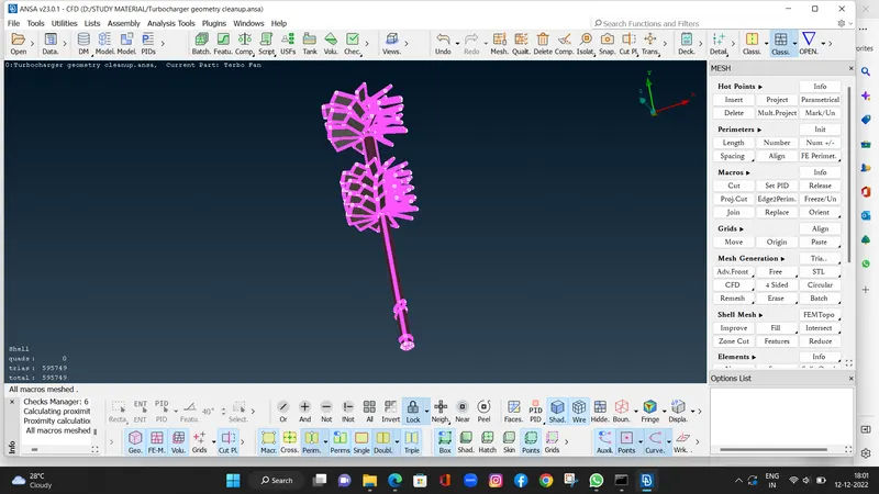
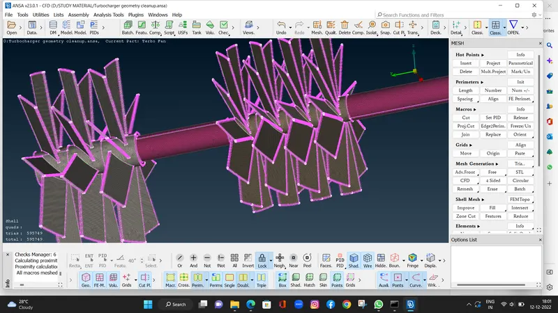
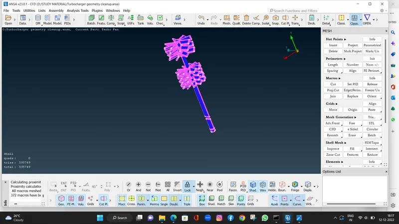
- After meshing there is showing 595749 MESHED Trias elements .
- There is not any unmeshed part.
ta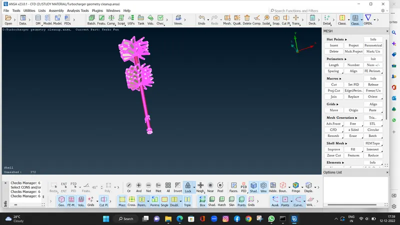
So accoring to the meshing conditions there is 2 mm target length for Impeller .
we will go to PIDS and off all the Assigned PIDS except Impeller.
Then in perimeters using spacing command select paerimeter and select the entire part and as well as macros then do middle click.After that we will go for Mesh generation in CFD and CFD VISIBLE command.
PERIMETER > SPACING > AUTO CFD > PERIMETER > SELECT GEOMETRY > MACROS > SELECT GEOMETRY > MIDDLE CLICK.
- Before go for mesh generation in spacing auto cfd it will ask maximun and minimum target length so we have 2 mm target length.
- Here I took maximum length 2.3 mm and minimum length 1.2 mm, then click ok.
- Now I can go for mesh generation.
MESH GENERATION > CFD > VISIBLE
- After meshing there is showing 14035 MESHED Trias elements .
- There is not any unmeshed part.
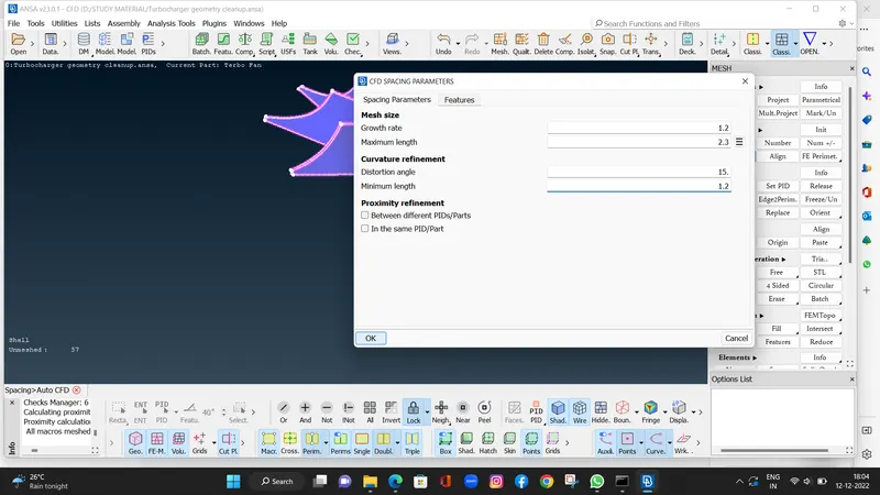
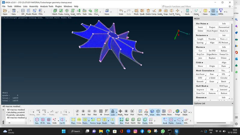
So accoring to the meshing conditions there is 2 mm target length for Turbo Casing , Impeller casing , Inlet.
we will go to PIDS and off all the Assigned PIDS Turbo Casing , Impeller casing , Inlet.
Then in perimeters using spacing command select paerimeter and select the entire part and as well as macros then do middle click.After that we will go for Mesh generation in CFD and CFD VISIBLE command.
PERIMETER > SPACING > AUTO CFD > PERIMETER > SELECT GEOMETRY > MACROS > SELECT GEOMETRY > MIDDLE CLICK.
- Before go for mesh generation in spacing auto cfd it will ask maximun and minimum target length so we have 5 mm target length.
- Here I took maximum length 5.09 mm and minimum length 4.85 mm, then click ok.
- Now I can go for mesh generation.
MESH GENERATION > CFD > VISIBLE
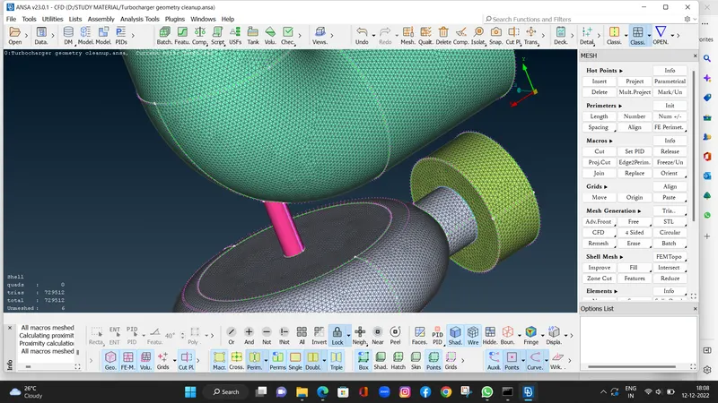
- After meshing there is showing 729512 MESHED Trias elements .
- There is 6 unmeshed part.
- we have solution for that.
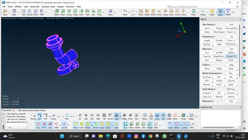
- we have to freeze the component after meshing part wise as per given target length.
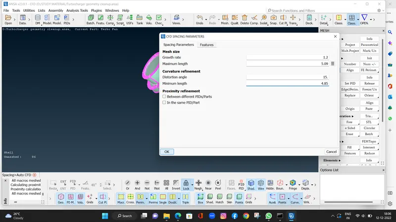
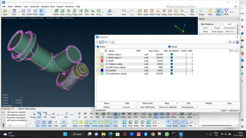
- There is showing 6 unmeshed elemets .
- I have command for that FREE MESH.
- But there is problem in that it will do random mesh so according to our given target length its not cover .
- So we have to go for freeze the component after meshing.
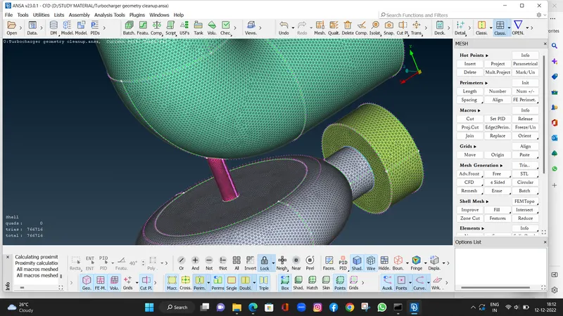
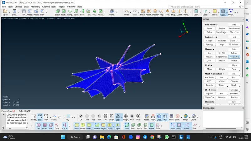
- Here we have freeze command for freezing the components for avoiding unmeshed elements.
- As we do before part wise meshing we will do as same but only we will use freeze command after meshing.
PERIMETER > SPACING > AUTO CFD > PERIMETER > SELECT GEOMETRY > MACROS > SELECT GEOMETRY > MIDDLE CLICK.
MACROS > FREEZE/ UN FREEZE >USING LEFT CLICK SELECT COMPONENTS
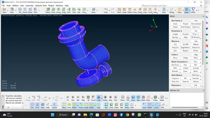
- This will freeze the components and there is not mismatching the perimeter during meshing.
- In result we can do all components meshed.
Step 3 : Volumetric meshing
- After surface meshing we will do volumetric meshing.
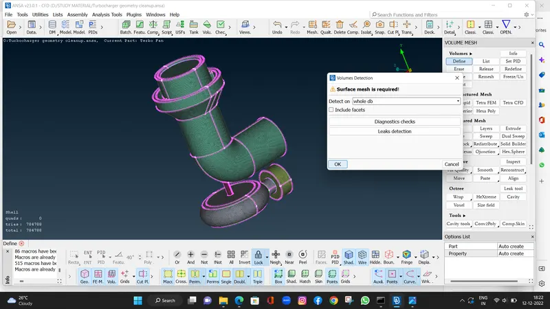
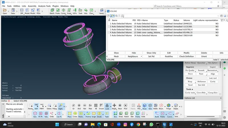
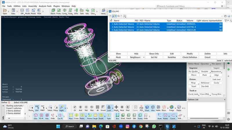
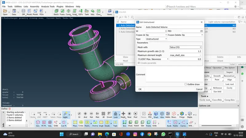
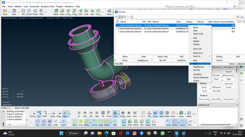
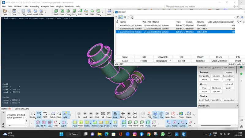
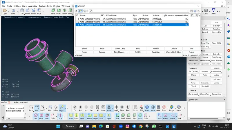
VOLUMETRIC MESHING > OK > DEFINE INTERNAL VOLUME > DELETE UNWANTED VOLUMES > DOUBLE CLICK > IN UNSTRUCTURED > TETRA CFD > OK > RIGHT CLICK ON VOLUMES > MESH.
After that we have meshed volumes.
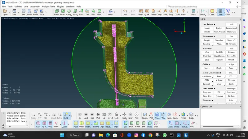
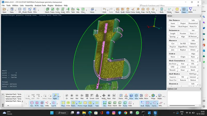
- PLANE CUT SECTION IN X-Y COORDINATES.
CUT PLANE > NEW > DEFAULT XY > SELECT HOT POINTS > NEW > DOUBLE CLICK > OK.
GEOMETRY FILES
- GEOMETRY CLEAN UP.
https://drive.google.com/file/d/13SyW8yvhanC1iQwQ0vegJLNfSa-NPqZ-/view?usp=share_link
- VOLUMETRIC MESHING.
https://drive.google.com/file/d/1KxbnAuU60Vmc63ATdJ_DXTFF-C-yl0Sg/view?usp=share_link