Week 3 Challenge : CFD meshing on Turbocharger
CHALLENGE-3: CFD Meshing on Turbocharger
AIM:
To perform volumetric meshing (CFD Meshing) on the given Turbocharger.
OBJECTIVE:
To open the given Turbocharger geometry in ANSA and to cleanup the geometry appropriately.
To carry out triangular meshing on the surface of geometry with different target lengths of 5mm, 2mm and 1mm on different parts as mentioned in question
To perform the volumetric meshing (CFD Meshing) of the same.
PROCEDURE:
- Open the geometry in the ANSA software and check the errors in geometry by Checks > Geometry> Execute.
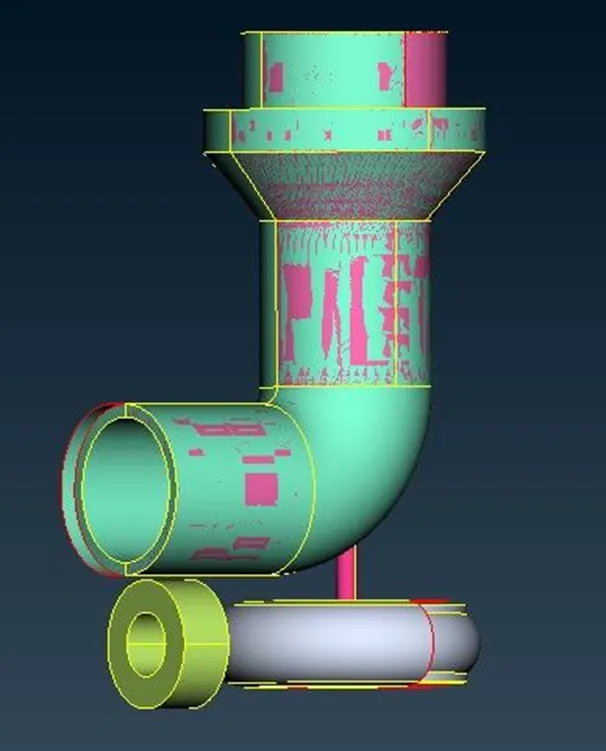
- Cleanup the surface of geometry by deleting overlapped and unwanted surfaces by using universal delete option and fill the gaps present by creating new surface from New option on the left tabular column followed by selecting either Existing Surf or COONS or FITTED option and selecting the single cons in the gaps. Fill Hole option can also be used for filling the holes presents. Remove the surfaces present inside the shaft. Sometimes triple cons present even deleting the surfaces eliminate those by Release and topo option.
-
- Create surfaces for inlet and outlet for compressor and turbocharger and use Paramteric option to create hotpoints at equal distance for making the surfaces. Find and delete the penetrated faces by using Intersect option under faces and deleting the penetrated faces.
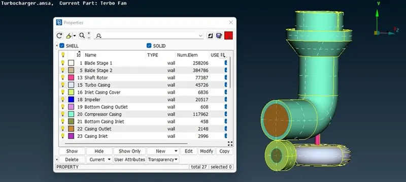
- After completing the cleanups provide each part with suitable PID name by selecting the Property from top tabular column and creating new PIDs and by renaming existing PIDs. Then assign each PIDs appropriately. The figure shown below represents the completed geometry.
- Now move to the meshing tab. On the meshing tab set the perimeter and macro length as mentioned.
- From the Mesh parameter drop down set meshing type as triangular and target length, Minimum and Maximum Target length. Set minimum and maximum target length in quality criteria also.
- On the left tabular column click on spot mesh under Mesh generation section and select each PIDs and do meshing.
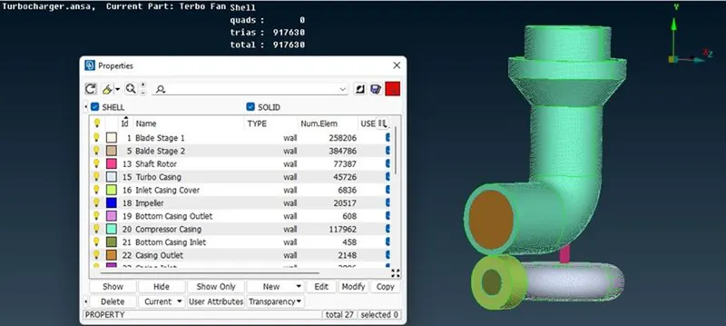
- Repeat step 5, 6, 7 with appropriate traget size. The parts where two different mesh size interact set the macro as varying mesh size of both the parts. The meshed geometry is shown below.
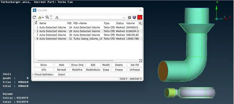
- After completing the surface meshing move to volume meshing tab, select Define and select auto detection. Here delete the unwanted volumes like the thickness of compressor, turboexpander, shaft and blade arrangement. Maintain the volume where the fluid flow take place. Then remesh the selected volume with Tetra CFD option. The figure shown below represents the volumetric meshing.
RESULT AND DISCUSSION:
The figure below shown represent the cross-section view of the volumetirc meshed trubocharger geometry.
From the figure shown above it is observed that near to the blades and shaft arrangement the size of mesh formation is very small as compared to other areas and meshes are only formed in the volume where the fluid flow would occur.
CONCLUSION:
The given geometry is studied and topological cleanup is carried out in the geometry. Then surface meshing and volumetric meshing of this geometry is carried out and results are discussed.