Week 3 Challenge : CFD meshing on Turbocharger
OBJECTIVE
- For the given model, check for the geometrical errors to make appropriate volumes. Create and assign PIDs as shown in the video. Perform surface mesh with the given target lengths as per PIDs.
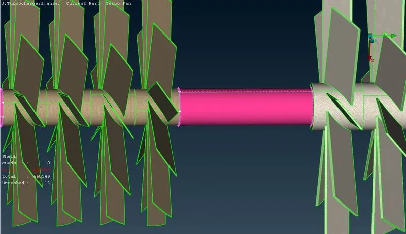
- Blade stage-1 = 1 mm
- Blade stage-2 = 1 mm
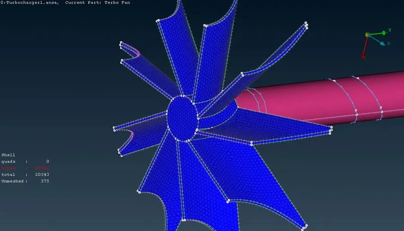
- Impeller = 2 mm
- Shaft rotor = 1 mm
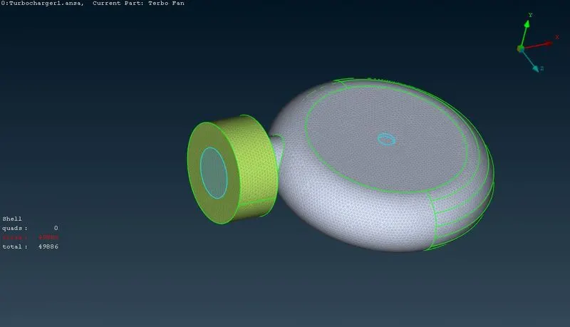
- Turbo casing = 5 mm
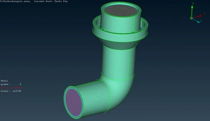
- Compressor casing = 5 mm
- Inlet casing cover = 5 mm
- Perform Volumetric mesh for the required volumes.
PROCEDURE
- Import the geometry to the ANSA pre-processor.
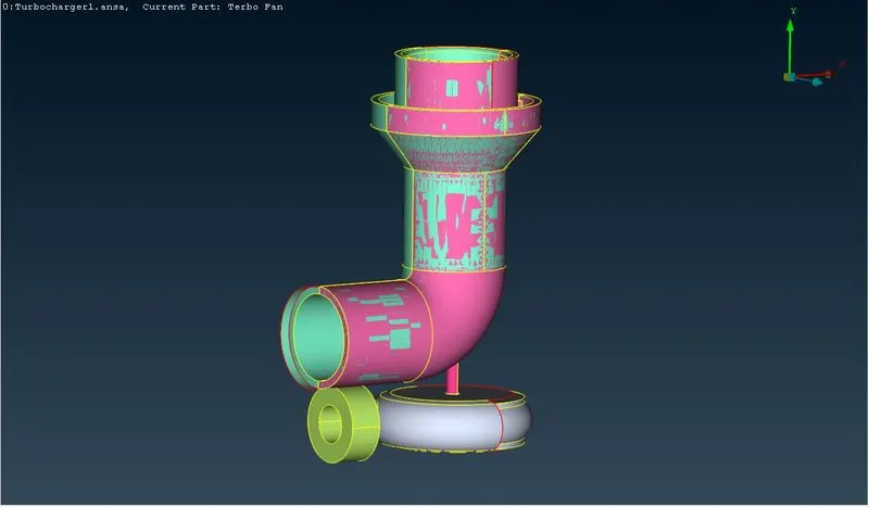
- Check for the geometrical errors (Tools>Checks>Geometry>Execute) as shown in the figure below.
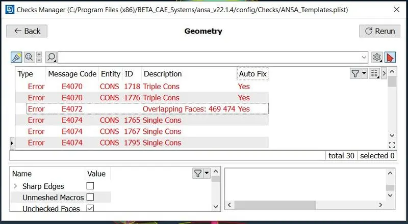
- As there are overlapping surfaces shown while geometry check is done, hence remove these overlapped faces present in the geometry (Topo>Delete>Select the surfaces to be deleted by Entity or PID region>Middle click).
- After the deletion of the overlapping faces the geometry looks like as shown in the figure below.
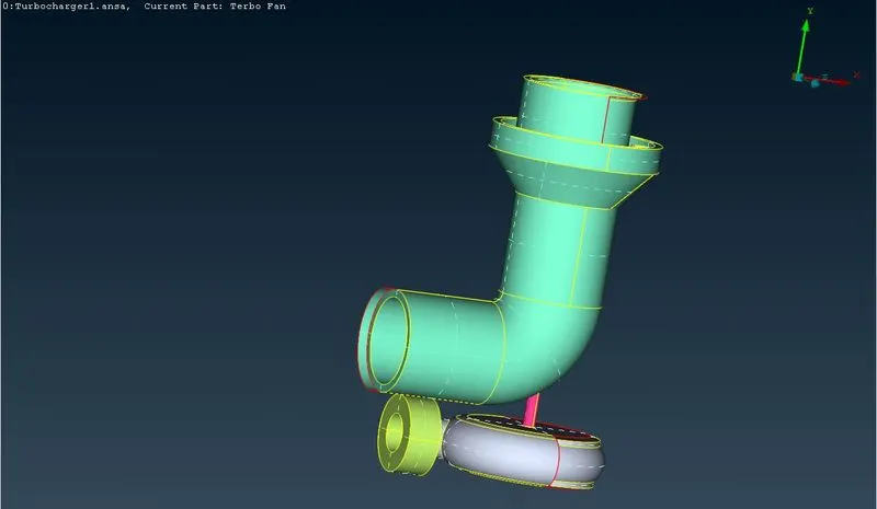
- Since the geometrical errors shows the single cons present, the next step is to transform these single CONS to double CONS by creating the new surfaces where ever required (Topo>Faces>Fill Hole/New>Existing Surf./Coons/Fitted).
- At some locations, new surfaces can't be created directly with the COONS/fill Hole function in order to rectify the single CONS error. One example for this issue is shown in the figures below.
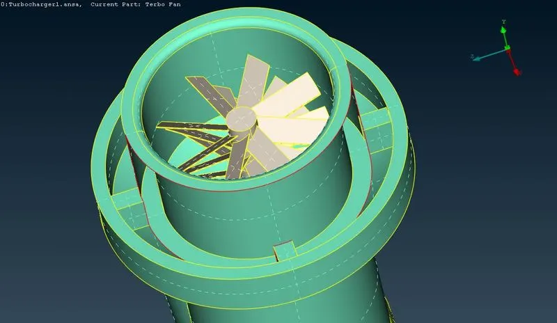
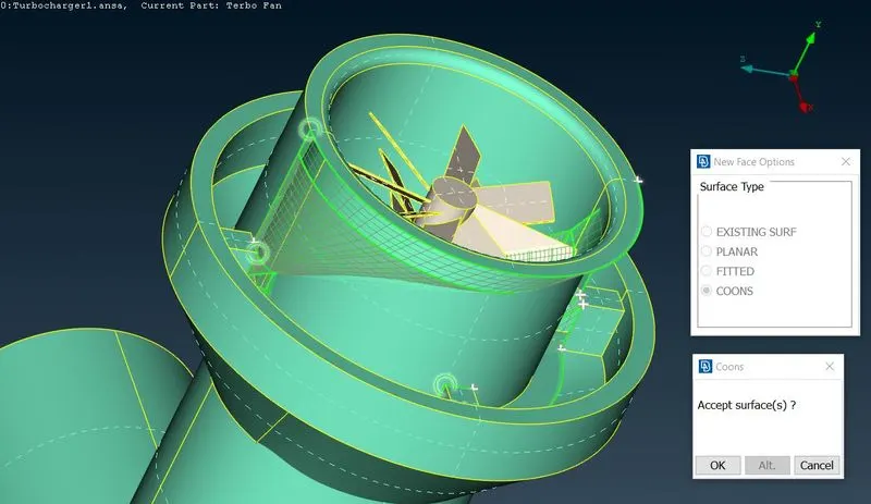
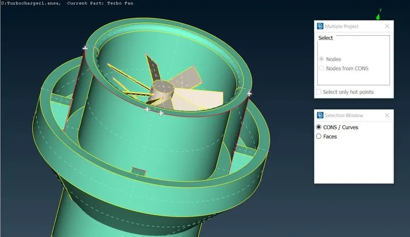
- To solve the above issue indirectly, several new surfaces are to be generated by projecting the hot points on the CONS (Topo>Hot Points>Mult.Project) as shown in the figures below.
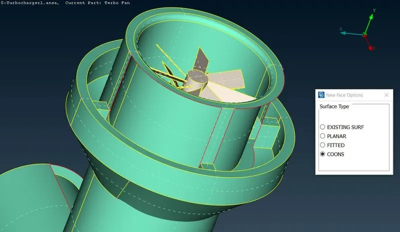
- Second example of the issue is shown in the figures below.
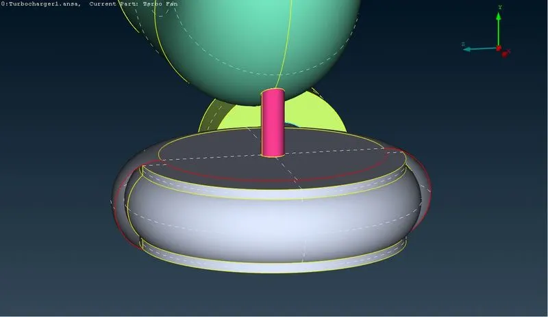
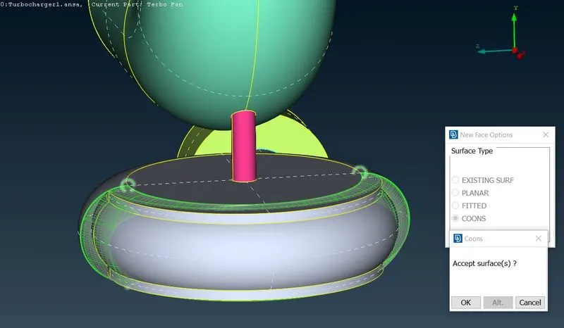
- To solve the above issue indirectly, several new surfaces are to be generated. For this to be done several new hot points are to be created (Topo>Hot Points>Parametrical) as shown in the figures below.
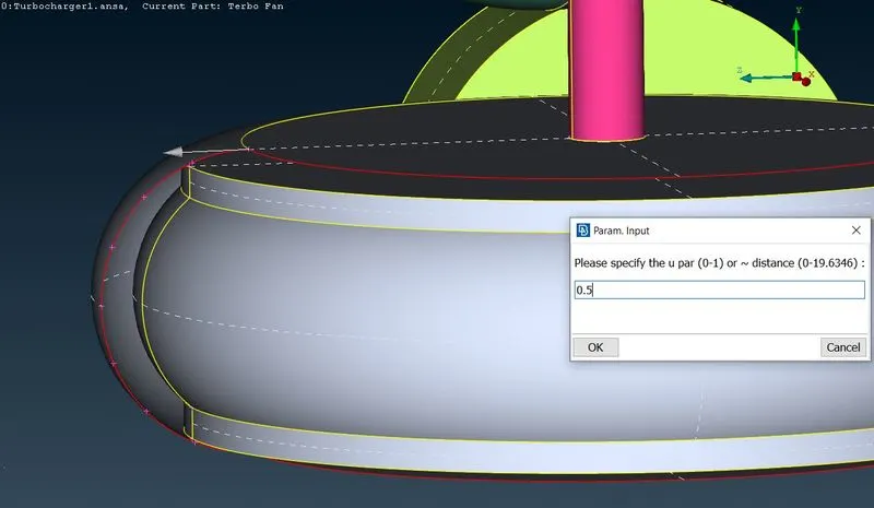
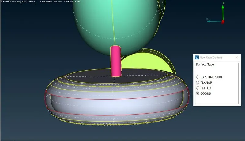
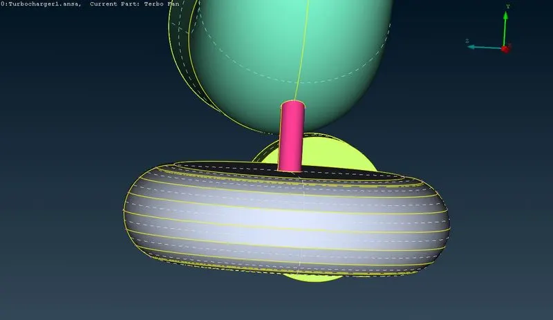
- Some extended surfaces hinder to generate the new surfaces. So first delete the extended surfaces inorder to generate new surfaces. As shown in the figures below there are two surfaces that passes through the other surface. So, first these surfaces are made to intersect using the intersect function (Topo>Faces>Intersect).
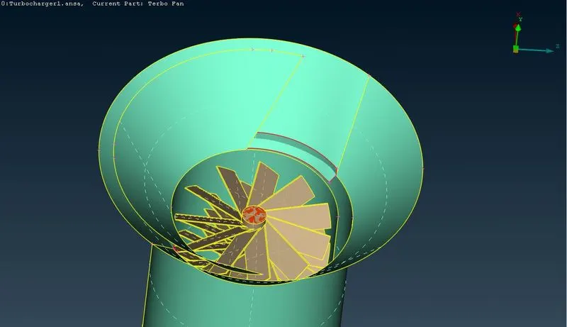
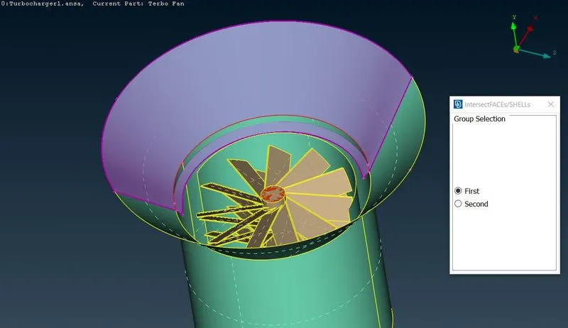
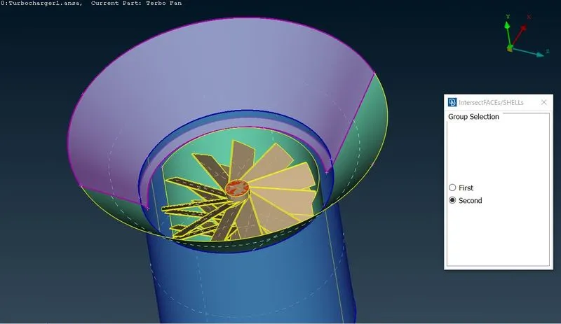
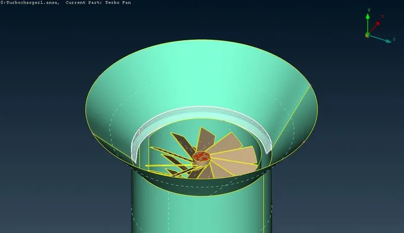
- After correcting every single CONS error by patching up the geometry, the next step is to do the surface meshing. In order to do this the geometry should be closed where ever the openings are present (Topo>Faces>New>Fitted) as shown in figures below.
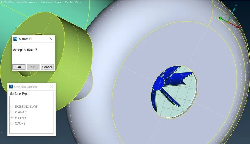
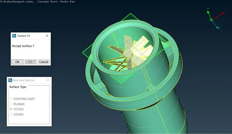
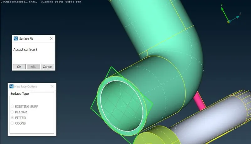
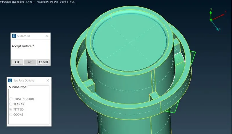
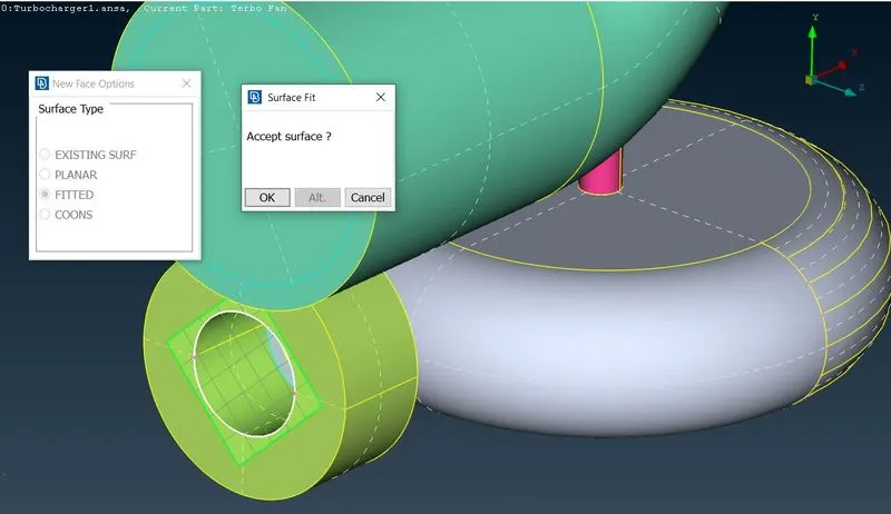
- Asign PIDs as shown in the figure below.
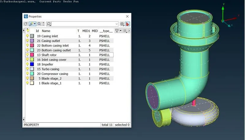 `
`
- Objective is to do volumetric mesh, hence first surface meshing is to be done with the given target lengths as per the PIDs.
- To generate surafce mesh for the compressor casing, specify the minimum length = 3mm and maximum length = 7mm in mesh quality criteria and also specify the target length = 5mm and element type as tria in the mesh parameters as shown in the figures below. Also asign perimeter and macros target length as 5mm.
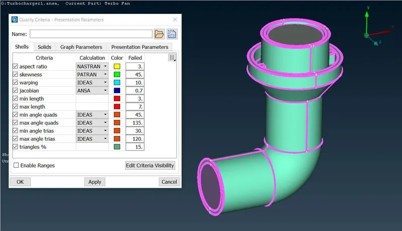
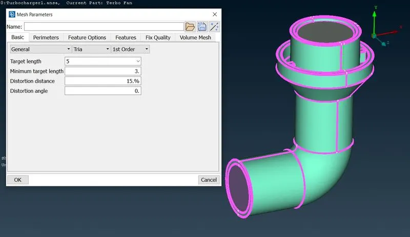
- To generate surafce mesh for the Turbo casing and Inlet casing cover, specify the minimum length = 3mm and maximum length = 7mm in mesh quality criteria and also specify the target length = 5mm and element type as tria in the mesh parameters as shown in the figures below. Also asign perimeter and macros target length as 5mm.
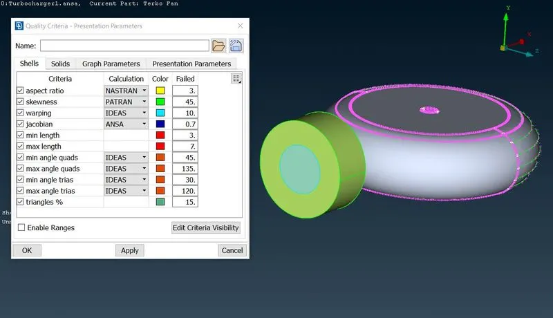
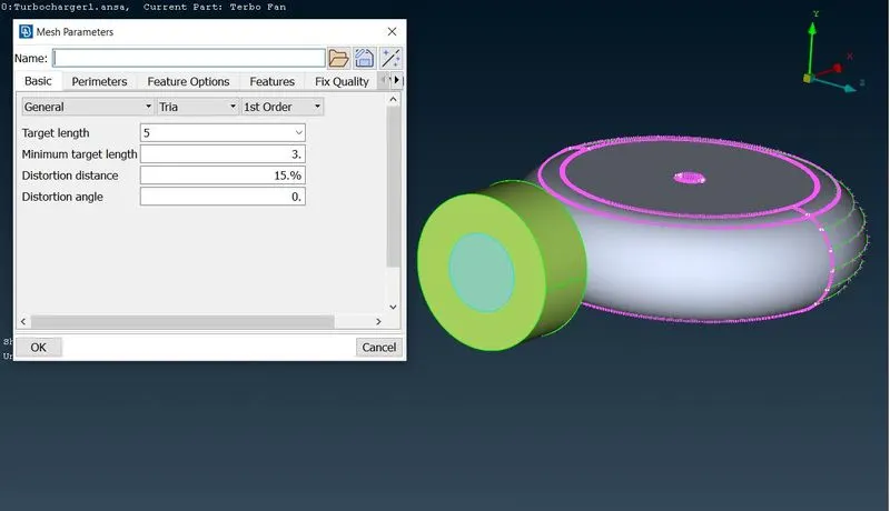
- To generate surafce mesh for the Impeller, specify the minimum length = 1mm and maximum length = 3mm in mesh quality criteria and also specify the target length = 2mm and element type as tria in the mesh parameters as shown in the figures below. Also asign perimeter and macros target length as 2mm.
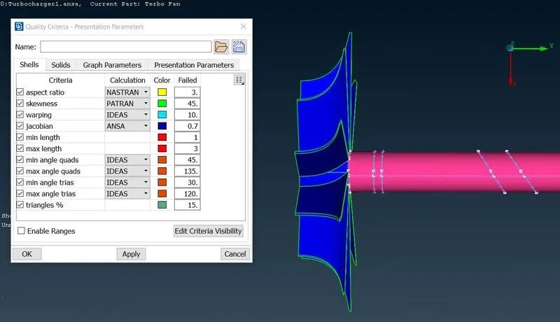
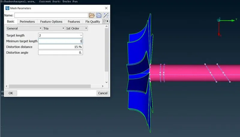
- To generate surafce mesh for the Blade stage_1,Blade stage_2 and Shaft rotor, specify the minimum length = 0.5mm and maximum length = 2mm in mesh quality criteria and also specify the target length = 1mm and element type as tria in the mesh parameters as shown in the figures below. Also asign perimeter and macros target length as 1mm.
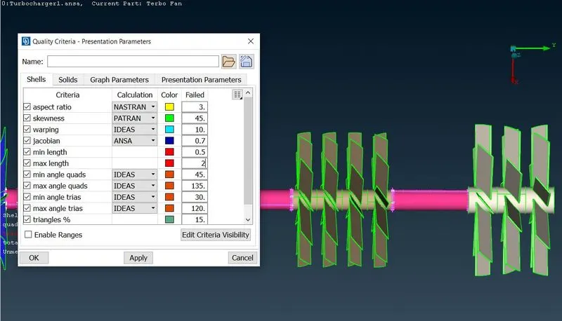
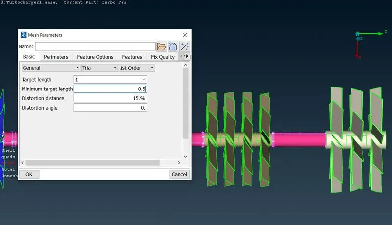
- To perform volumetric meshing, first define the volumes (Volume Mesh>Define>Volume detections) as shown in the figure below.
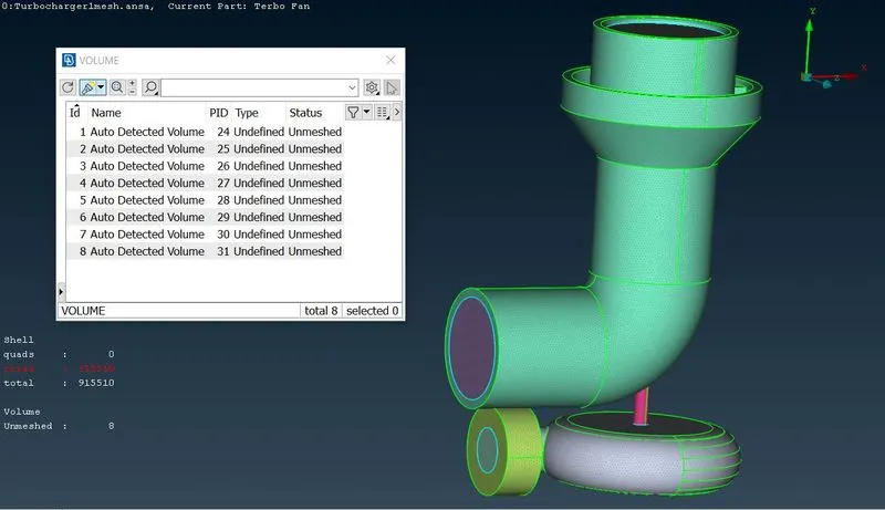
- After auto detecting the volumes, delete the volumes that are not required for volume meshing and keep the volumes where the fluid flow happen as shown in the figure below.
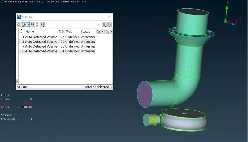
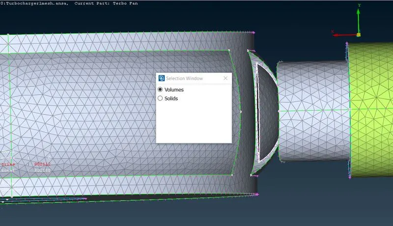
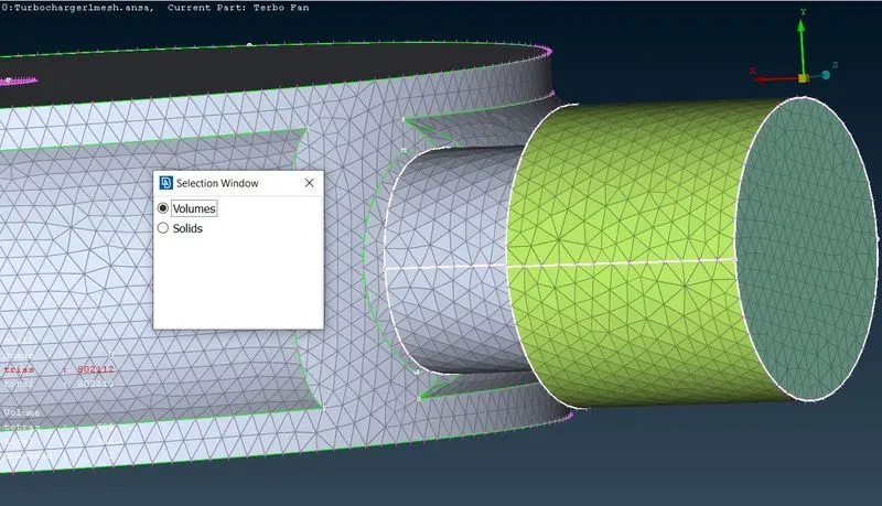
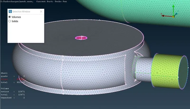
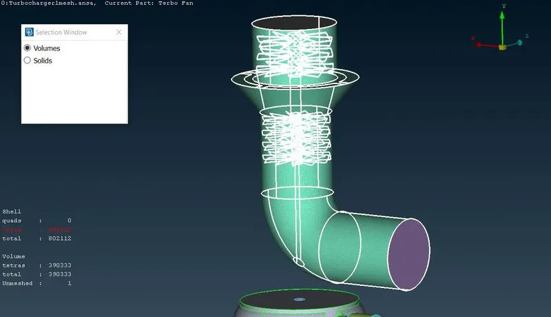
- Perform volumetric meshing on undeleted volumes (Volume mesh>Unstructured mesh>Tetra CFD) as shown in the figures below.
LEARNING OUTCOME
- Surface meshing is a pre-requisite of volume meshing.
- To perfome volume meshing, always define the volumes that require volume meshing.
- Volume mesh will be done only where the volumes are not occupied or taken by the parent geometry i.e., volume mesh will be done in space or voids which is present inside the geometry where the fluids flow.
RESULTS
- Compressor casing surface mesh of target length = 5mm is shown in figure below.
- Turbo casing and inlet casing cover surface mesh of target length = 5mm is shown in figure below.
- Impeller surface mesh of target length = 2mm is shown in figure below.
- Blade stage_1 and Blade stage_2 surface mesh of target length = 1mm is shown in figure below.
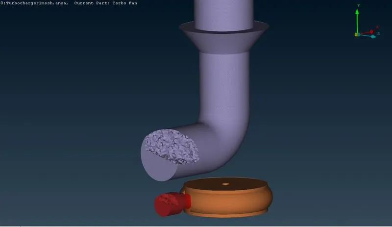
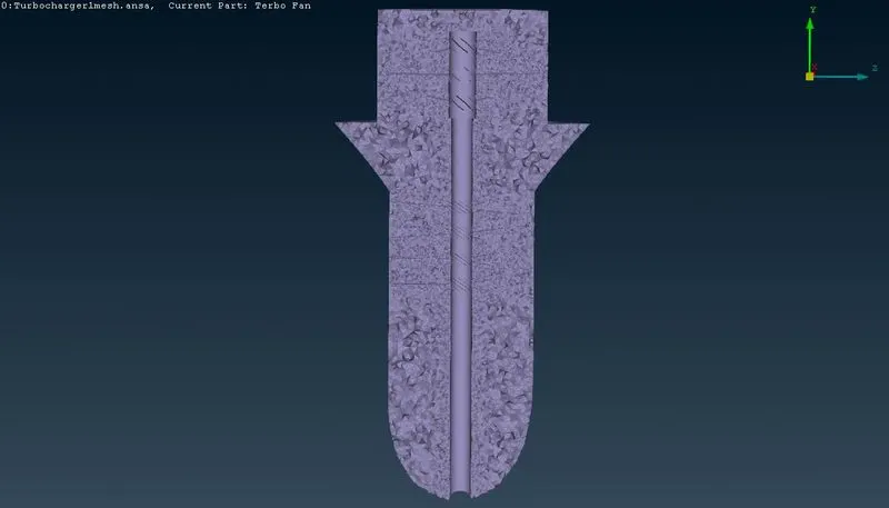
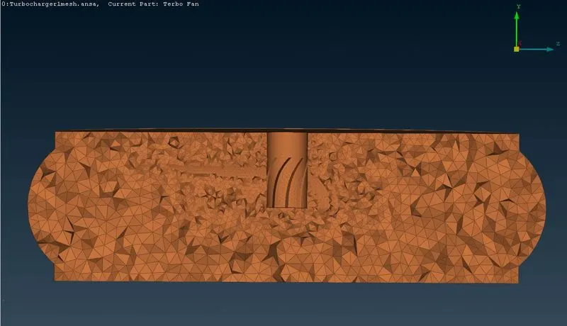
- The figures shown below is the volume mesh of the fluid flow region.
CONCLUSION
- Surface meshing and volume meshing is done for the given Turbocharger geometry.
- t is observed that near to the blades and shaft arrangement the size of mesh formation is very small as compared to other areas
- Meshes are only formed in the volume where the fluid flow would occur.
NOTE : Due to large file size of about 421MB, I couldnot upload the worked file with this report. I have tried uploading it but it cancels automatically.