Week 3 Challenge : CFD meshing on Turbocharger
AIM:
This project aims to mesh a turbo charger for conducting CFD analysis.
OBJECTIVE:
The main objective of the given challenge is to perform surface mesh and volume mesh on turbo charger and also geometry clean up with the surface mesh for the PID's as
Blade stage-1 = 1 mm
Blade stage-2 = 1 mm
Impeller = 2 mm
Shaft rotor = 1 mm
Turbo casing = 5 mm
Compressor casing = 5 mm
Inlet casing cover = 5 mm
INTRODUCTION :
Turbocharger :
A turbocharger, colloquially known as a turbo, is a turbine driven forced induction device that increases an internal combustion engine's efficiency and power output by forcing extra compressed air into the combustion chamber with the help of exhaust from an engine.
Steps to Follow:
- Import the CAD model.
- Topo/Geometry cleanup.
- Geometry check-up.
- Setting-up of relevant PIDs.
- Defining the element size or length.
- Selection of Meshing type.
- Generating surface meshing the CAD model .
- Generating volumetric mesh.
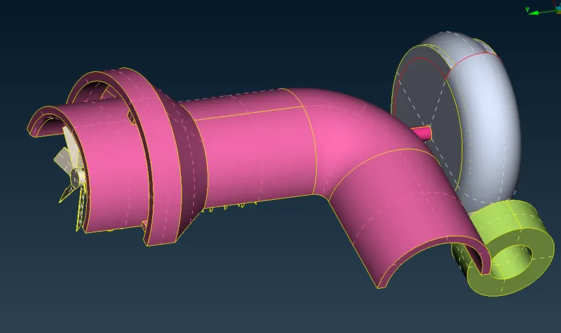
Once the cad model is imported, we can see that there are errors present in the model.
We need to start by cleaning those errors.
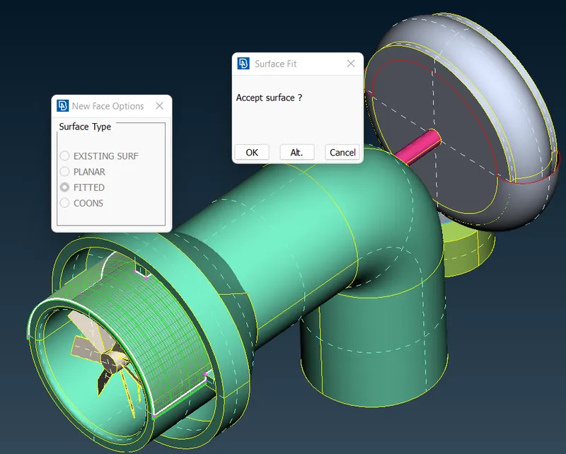
Creating a new surface at the compressor casing inlet :
- At the compressor casing inlet you will see a open surface bhaving single cons. By using fitted options under New (under faces ) we create a new surface.
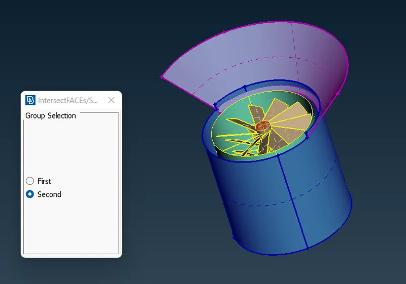
Intersecting the surfaces :
- Then the next single con error is seen where there is no intersection when intersected.Then we have to use intersect.
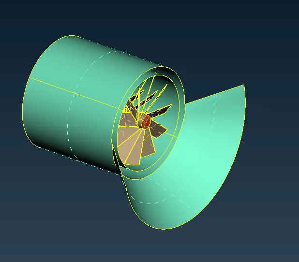
Creating new surface on turbo casing :
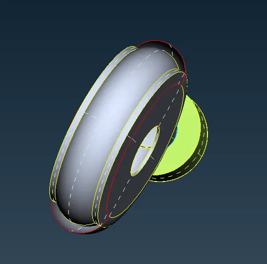
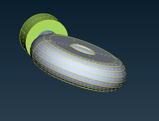
- If we create a new surface by using coons , you will see a irregular surface is formed.Then we have to insert some hot point on the edges.For creating of hot points we use parametrical under hot points and give length as 0.5. Then it create hot point at the center.
- We create hot points on both sides and create new surfaces using it , so that we get a smooth surface covering the casing.

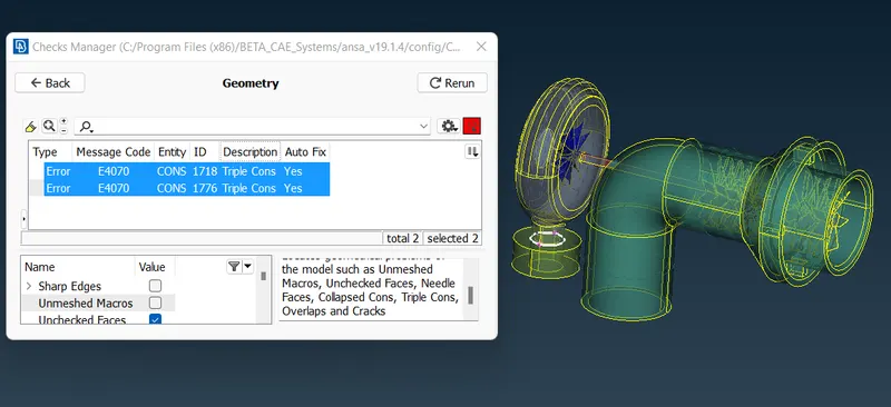
Geometrical checks go to checks -> geometry -> then execute.
Assigning The PIDs:
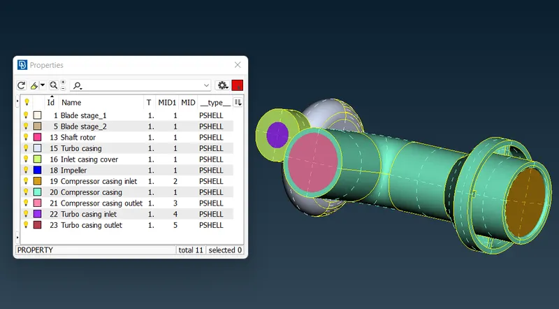
To apply , we select /click on the PID to apply in the PID manager -> then right click on it -> then click on apply -> then in the geometry select the cross hatch of the surface you want to assign -> then middle click.
Element size/lenngth:
we give blades and rotor a target length of 1 mm,casings a length of 5 mm and impeller 2mm.You can observe here that blades are given lower length because it is a very important component in the CFD analysis and it should be as refined as possible.
Mesh Selection & Generation:
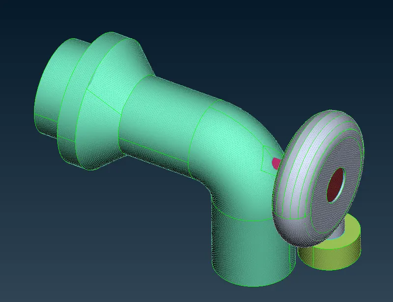
Go to Mesh Generation -> spot Mesh -> tria -> drag and select the required model -> click on the scroll button/ middle mouse button on mouse to mesh (or) we can directly select visible under drop down menu of spot mesh instead of drag and select the entire model after seperating them by using NOT.
Volumetric Mesh:
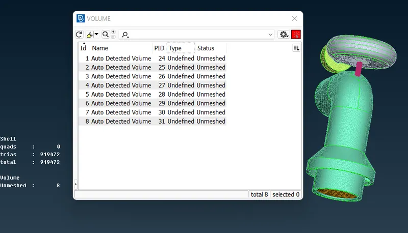
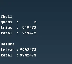
- After deleting, we have 4 volumes where flow is happening then we have to do volumetric mesh for them .
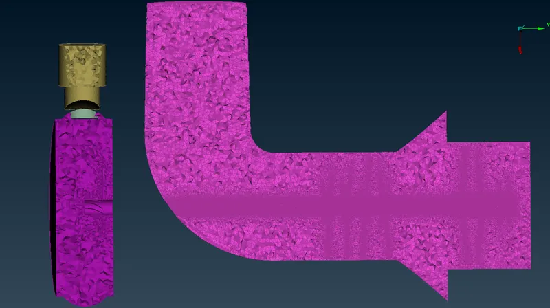
- For volumetric mesh to be done under unstructured mesh use tetra CFD .By removing some parts of the elements we can confirm visually volumetric mesh is created by seeing multiple elements inside and slots for blade properties.
CONCLUSION