Week 3 Challenge : CFD meshing on Turbocharger
CFD meshing on Turbocharger:
AIM:
To mesh a Turbo charger for conducting CFD analysis using ANSA.
Objective:
* To check for the geometrical errors for the given model of a turbocharger, to make appropriate volumes.
* To Create and assign PIDs accordingly.
* To Create surface mesh and making use of that we can create a volumetric mesh(Tetra CFD).
Perform surface mesh with the given target lengths as per PIDs.
- Blade stage-1 = 1 mm
- Blade stage-2 = 1 mm
- Impeller = 2 mm
- Shaft rotor = 1 mm
- Turbo casing = 5 mm
- Compressor casing = 5 mm
- Inlet casing cover = 5 mm
Given Model:
There are three steps to do after opening the model and before performing anything.
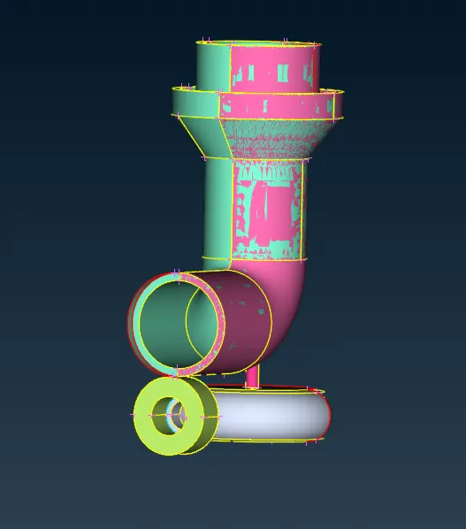
Here with this attached image we can see that glitches, which in turn results because of the overlapping surfaces

Procedure:
* Checking the unit dimensions. * Checking the resolution of the model if there is any distortion we shall change perimeter size to make it right. * Geometry clean up - to find geometrical errors so that we can rectify it, so that there won't be any errors poping up like single cons, triple cons, intersection errors
After clearing all those popping errors, we get errorless geometry for further surface meshing process,

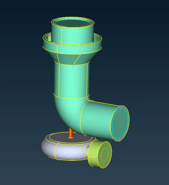
Now we have a geometry in which we can proceed with naming PID's and surface mesh after that, PID's are named as below
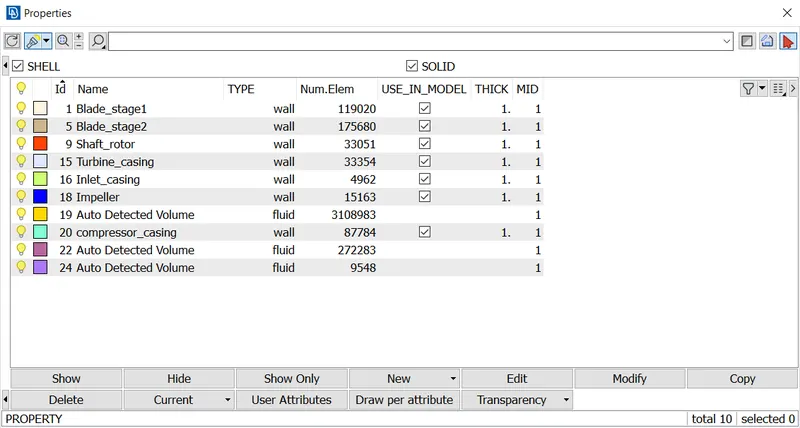
* Though we are conducting a CFD analysis of an Internal flow, we have to close the openings with lids , which in turn shows a triple cons warning as its unavoidable and we won't clear those warnings which is unavoidable.
The components and its meshed are,
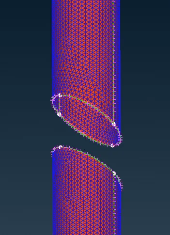
Shaft Rotor,
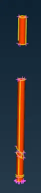 >>
>> 
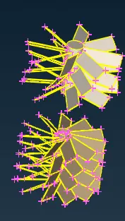
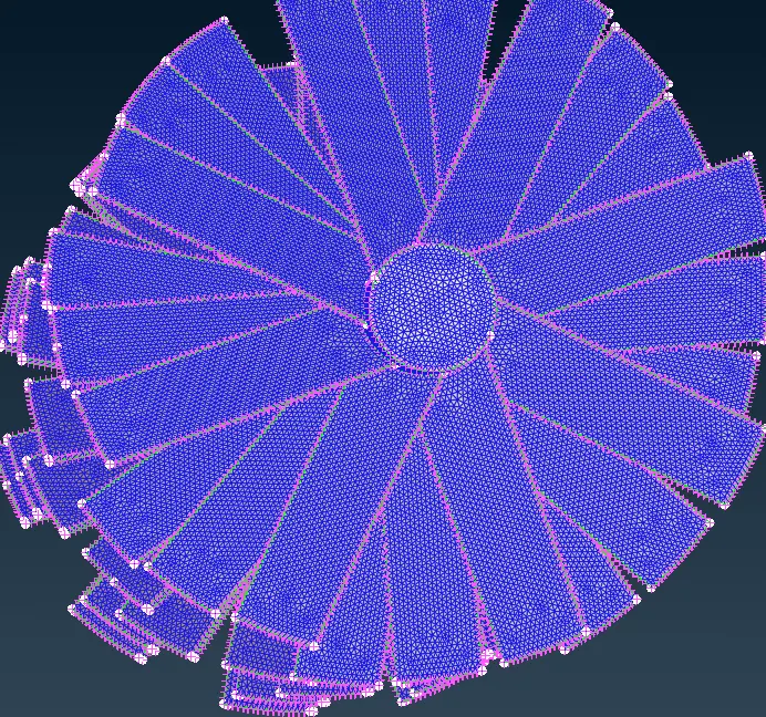
Blade stage 1&2,
 >>
>> 
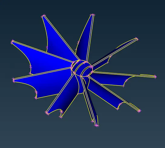
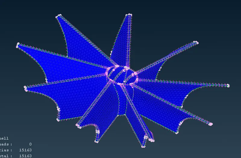
Impeller,
 >>
>> 
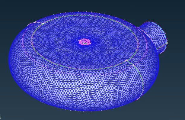
Turbine casing,
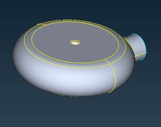 >>
>> 
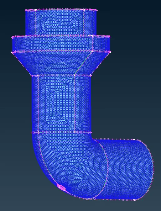
Compressor casing
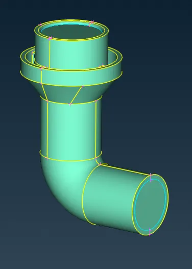 >>
>> 
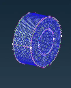
Inlet casing,
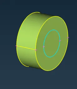 >>
>> 
An Auto CFD mesh is created by, In Perimeter -> Spacing -> clicking on the Auto CFD tab -> defining Perimeter and macros.
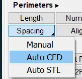
Then under mesh generation tab -> CFD -> Visible.
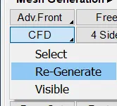
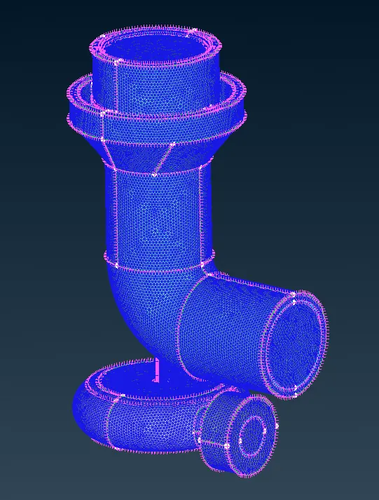
Here we created surface mesh of different target lengths to the various components of Turbocharger, But when every components mesh is displayed, there will be mesh error because of different perimeter lenghts coming into contact.
This can be rectified by freezing the visible meshed entity after meshing every components , so that the mesh of the component won't get erased and when displaying all components doesn't result in erasing mesh.
Freezing is done by clicking on Freeze tab under Macros.
freezed mesh also freezes its perimeter length given, after freezing the surface mesh, We can see that at the place where the shaft meets the components having different target length. The mesh adapts such that there is a connectivity between the two components because of freeze option.
Volume mesh
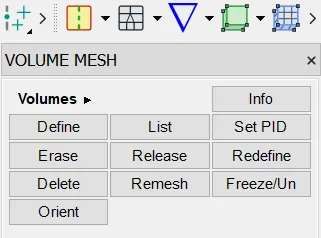
For generating a volumetric mesh we go to the right side menu and in the volume tab -> Define -> use the entire database and press ok.
It should detect a total of 5 Detected volumes in the list. In those 5 volumes we need only 3 volumes which are needed because we are going to conduct internal flow analysis. These volumes are the thickness of all the components.
It should be as shown, the figure attached below was taken after deleting the unwanted volumes,
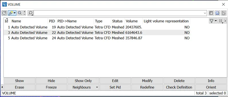
Once the required volumes are extracted we right click on these volumes select mesh and select Tetra CFD.
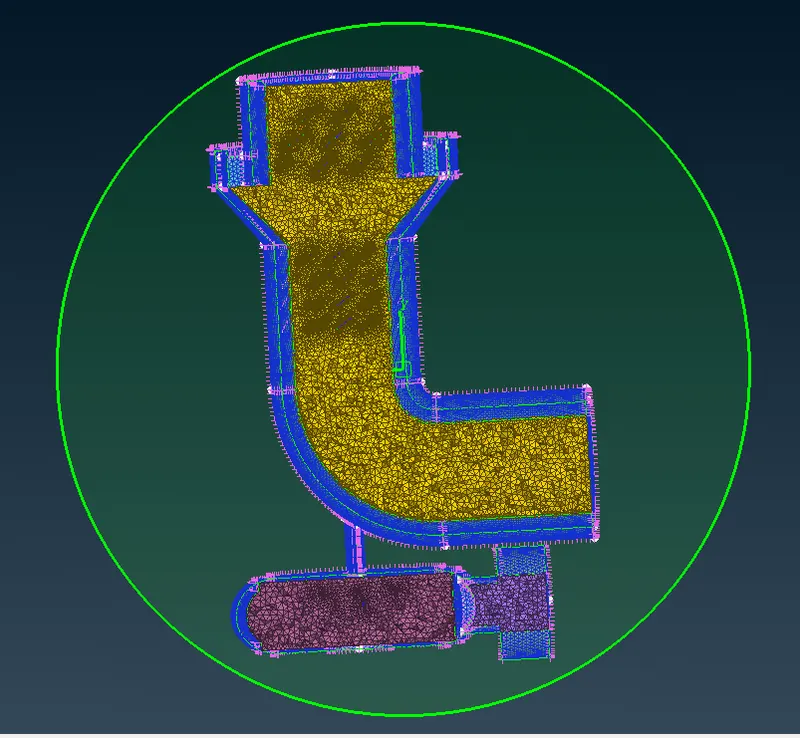
After creating a Tetra CFD mesh, we can cut the planes using cut planes option(we have selected XY plane) to visualize the created Tetra CFD mesh.
Figure shared below is after cutting the plane to visualize Tetra CFD mesh in the components.
Conclusion and Outcomes:
* Achieved volumetric mesh of the given turbocharger model.
* Used transform option under curves tab to create curves with a reference curve and reference points
* Different mesh length size tend to give errors at the contact regions of 2 different mesh length regions, therefore Freeze option to avoid erasing of mesh.
* Volumetric mesh will be achieved only after creating surface mesh, To create Surface mesh we have to be free of errors except unavoidable warning.
* Overlapped surface can be deleted using the universal delete option.
* Unecessary single and triple cons can be removed and editted using different tools and I have learnt that in this challenge.
*Mesh file's link is attached - https://drive.google.com/file/d/1KOLwVSM6l22UbPX0VRuM4eUo2ygi1utR/view?usp=drivesdk