Week 3 Challenge : CFD meshing on Turbocharger
CFD meshing on Turbocharger
AIM/OBJECTIVE:
For the given model, to check for geometrical errors to make appropriate volumes, create and assign PIDs. To perform surface mesh with the given target lengths as per PIDs and perform Volumetric mesh.
Procedure:
Initially, the given model was loaded in Ansa.
Geometrical Cleanup:
The given model was not properly good on the surface hence we need to clear the topological errors by using the Topo module.
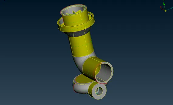
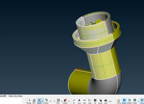
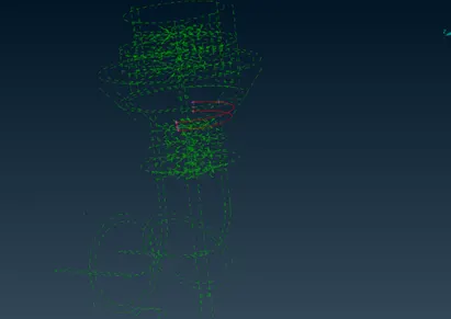
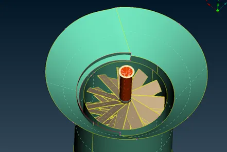
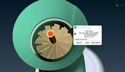
Here we had many single cons. So at first, we need to remove the single cons by creating new faces and deleting the unwanted and overlapped faces.
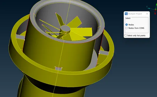
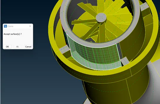
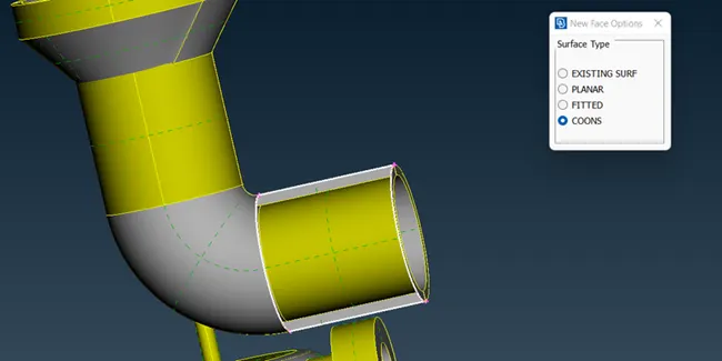
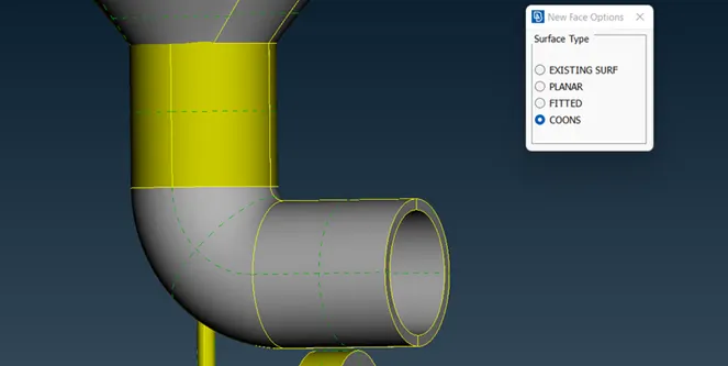
The parametrical option was used to create hot points and cut cons
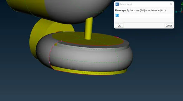
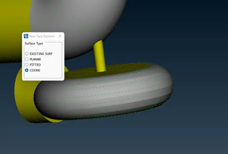
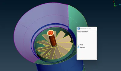
The intersection option used to separate the face which is two faces creates unwanted by intersecting each other.
after all single cons are removed successfully., it's time to handle triple cons.
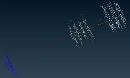
The triple cons are removed by deleting overlapped faces everywhere.
after that, the open holes are closed by the Fill hole option.
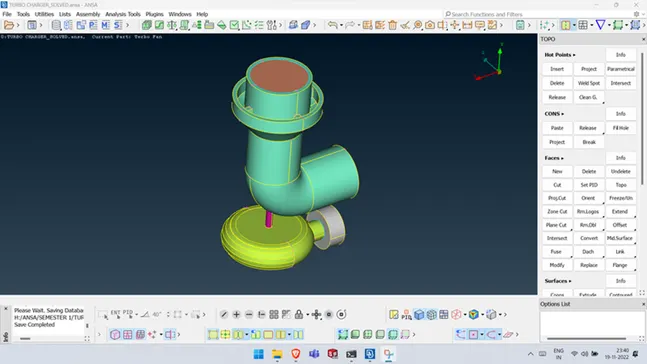
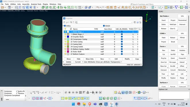
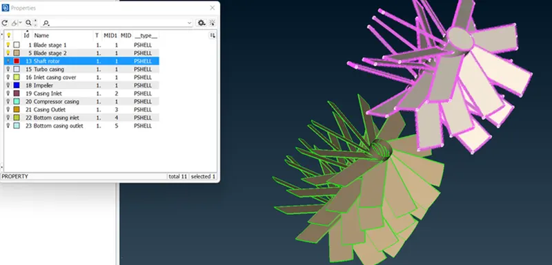
After all topological and geometrical issues have been solved PIDs are assigned as shown in fig.
MESHING:
Before moving to Volumetric mesh we first do the meshing.
So before meshing, we check for geometry and we see only the triple cons.
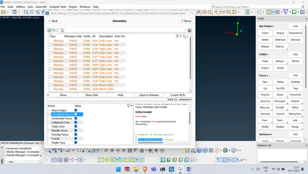
MESH LENGTHS:
- Blade stage-1 = 1 mm
- Blade stage-2 = 1 mm
- Impeller = 2 mm
- Shaft rotor = 1 mm
- Turbo casing = 5 mm
- Compressor casing = 5 mm
- Inlet casing cover = 5 mm
For compressor casing with 5mm target length
Meshing will be done in order to follow the procedure.
- Select the Pid which we need to mesh
- Then define the Quality Criteria like max length minium length and skewness etc.
- After that maximum and minimum Length of mesh was a provided in Mesh Parameters.
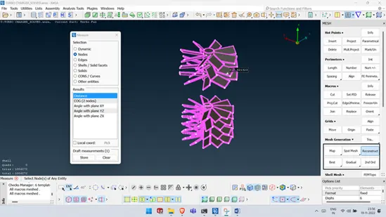
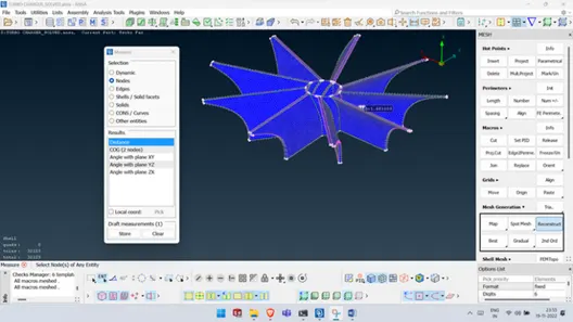
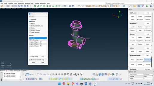
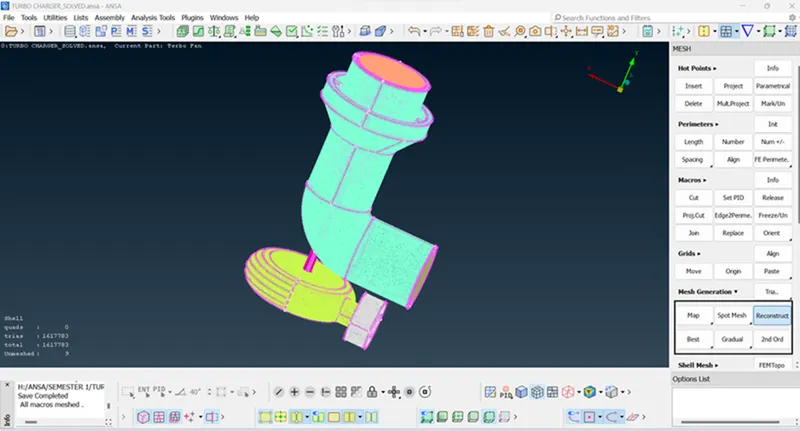
- Mesh length was provide in the Length option under Parameter optionas show in fiig
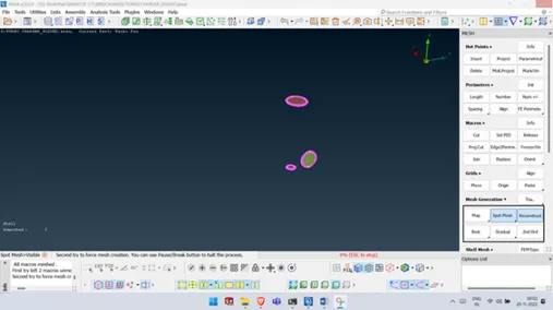
- After that Mesh generation we using the Spot Mesh option under Mesh Generation as shown in fig.
VOLUMETRIC MESHING:
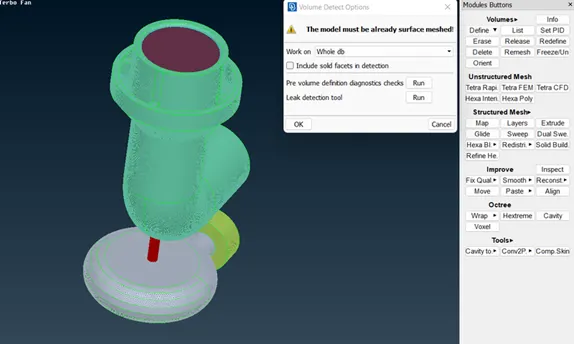
The first step in volumetric meshing we need to define the volume
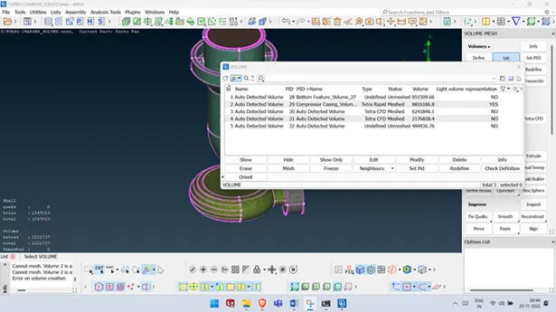
The defined volumes are listed.
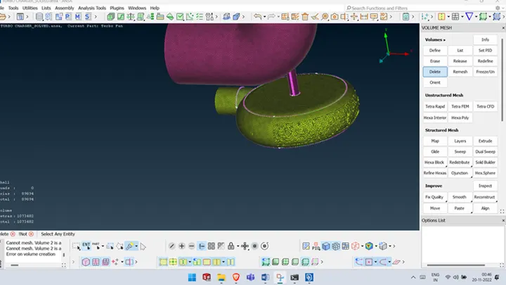
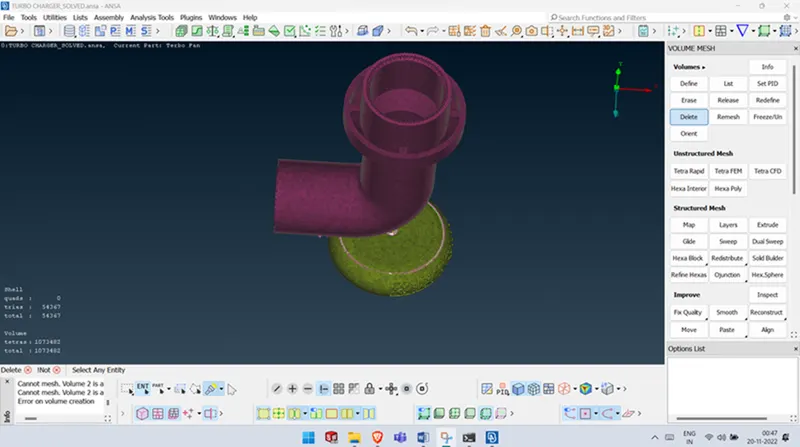
All required volumes which are needed to be mesh are selected and meshed by using Tetra CFD
After the meshing once done Now if we change to Topo mode we see glitching as the volumetric mesh is generated.
Also, we see where there were blades and shaft the volume varying 1mm to 5mm thereafter 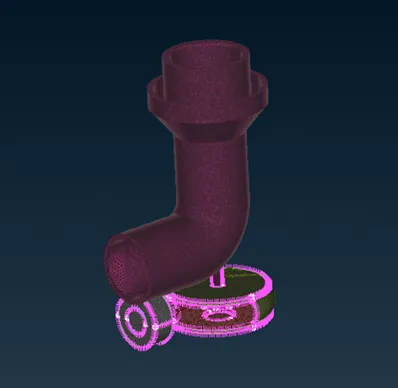
CONCLUSION:
Thus, the geometrical errors like single, double, and triple con are checked and PIDs are assigned accordingly to the requirement and the surface is generated for the given target lengths. Then volumetric meshing is performed for the volume required successfully.
LINK FOR SOLVED MODEL: Click here to download