Week 3 Challenge : CFD meshing on Turbocharger
CHALLENGE REPORT :
AIM:
To check for the geometrical errors to make appropriate volumes for the given model and perform Volumetric mesh for the required volumes.
OBJECTIVE :
* To check for the geometrical errors to make appropriate volumes for the given model.
* Create and assign PIDs for the model.
* Perform surface mesh with the given target lengths as per PIDs.
* Perform Volumetric mesh for the required volumes.
THEORY :
MESHING :
Meshing is the process of dividing a 3D model into thousands of elements to properly define its shap, the more detailed the mesh, the better the approximation. Meshes are used to run engineering simulation, communicate manufacturing data, or for rendering.
There are two main types of meshes: surface meshes and volume meshes:
Surface meshes :
Surface meshes use two-dimensional elements, typically triangles or quads, to approximate the outer surface of a 3D body. Surface meshes are used in manufacturing or rendering applications and CAE simulation.
Volume meshes :
Volume meshes, also known as solid meshes, use three-dimensional elements — typically tetrahedrons, hexahedrons, and polyhedrons, to define both the surface and interior structure. Surface meshes can be converted into volume meshes to run FEA or CFD simulations.
PROCEDURE :
i) Applying Geomentry checkup:
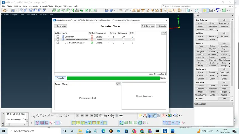
* Select the check option.
* Enter the check manager and select the geomentry and exicute it.
* Clear all the geomentry and intersection errors.
ii) Patch the missed surfaces:
- First we need to import the geometry model from the source folder.
- The geometry file contains lot of ir-regularities, discontnuities, so we need to patch all the missing and open surfaces in the geometry.
- This can be done by using the variours tools in the topo tab.
Some important tools to edit and coorect the patches in the model:
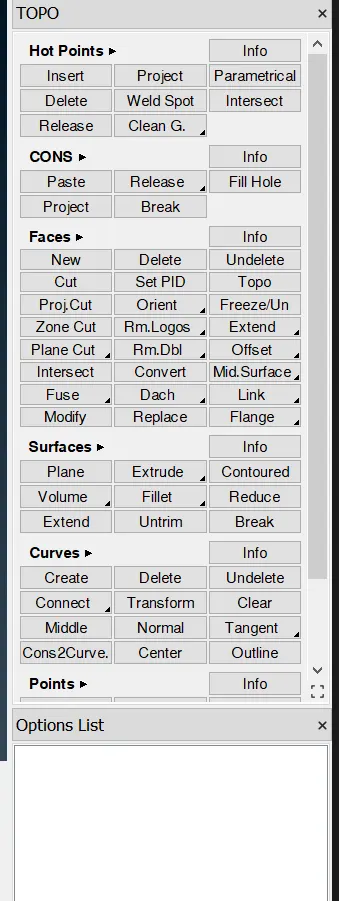
i) Faces (new, cut, intersect, Topo)
* The new option in the faces is used to create the new faces or surfaces by selecting the cons. It has four sub option like existing surf, planar, fitted, coons to create the surfaces depends on usage.
* Cut option is used to cut or separate the surfaces.
* Intersect option is used to correct the intersection error.
* Topo is used to auto correct some of the single coons and some geomentrical errors which can be corrected by the option.
ii) Coons (fill hole, project)
* The fill hole is similar to new option in faces, it is uaed to fill the surfaces if any open surfaces is present.
* Project is used to project the coons frome one surface to another surfaces.
iii) Hot points (insert, delete)
* The inset is used to insert the hot hots at the surfaces.
* Delete is used to delete the hot points.
iii) Removing overlapped surfaces:
- At some areas of the geometry, we need to clear the overlapped surfaces.
- This can be done by following procedure;
TOPO → delete → select the surface to be deleted by using entity or PID mode.
- Sometimes we need to project the cons to make the single cons into triple cons.
- This can be done by the following procedure;
TOPO → cons → project → select the cons → middle click → select the face where the cons has to be projected → middle click.
iv) PID assigning:
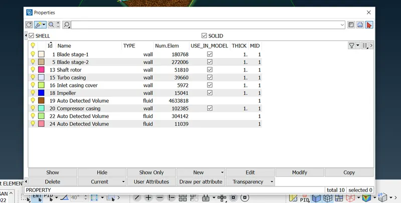
- Now we need to create PID (Property ID) for all the surfaces like inlet, outlet, spring, column, base and valve head.
- This can be done by the following procedure;
Properties → right click on the properties screen → new → PSHELL → PSHELL → box pops-up → name has to be given.
- Similarly we need to create as many as required.
- Now we need to assign the created PID 's to the respective surfaces required and we need to make sure that cross-hatches option is enabled.
- This can be done by the following procedure;
Properties → right click on the PID → apply → select the cross hatch present in the surface of the geometry → middle click on the mouse.
- Similarly we need to do for all the required surfaces.
v) Surface mesh process:
- Now we need to mesh the geometry.
- This can be done in two ways;
- Meshing the whole geometry in one shot. (only with single element length can be done at a time)
- Meshing the geometry part by part individually. (each part or component can be given different element length)
- The secomd method is employed in this challenge, however the second is highly beneficial when meshing distinct pieces with varying target lengths.
- Messhing can be done by following procedure;
MESH (right side on the screen) → perimeters → length → perimeters → give the target length → ok.
Mesh parameters (Top of the screen) → give the target length, min and max length in that dialog box.
Mesh generation (right side on the screen) → CFD → vissible
vi) Volume mesh process:
- Now we need to move to volume mesh.
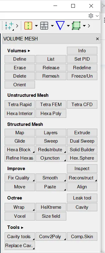
Volume → define → work on → whole db.
- Now we need to drop volume mesh to the geometry.
- This can be done by following procedure:
Volume → list → here we need to select the component to do volume mesh → right click → remesh
MESH OUTPUTS :
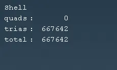
Surface mesh:
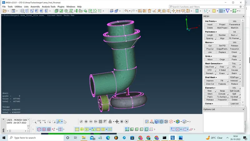
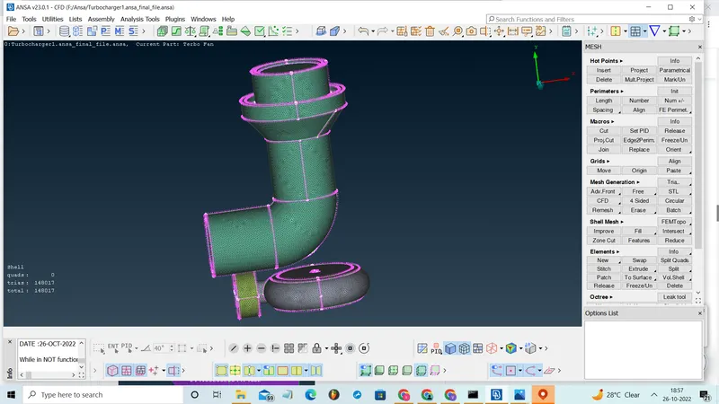
Turbo casing, Compressor casing, Inlet casing cover :
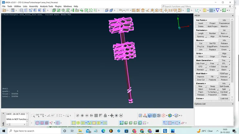
Blade stage-1, Blade stage-2, Shaft rotor :
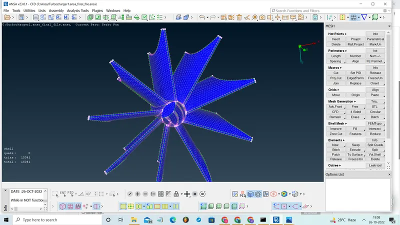
Impeller :
Volume meshes :
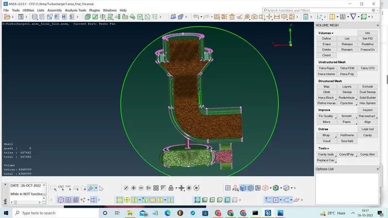
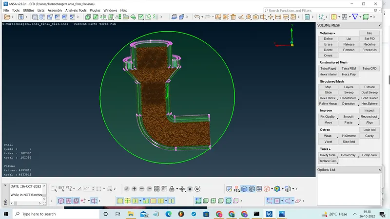
Turbo casing :
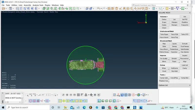
Compressor casing, Inlet casing cover :
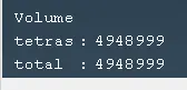
Meshed file link:
https://drive.google.com/file/d/1Rt0BPtsShCCDhqNMc5UHVckAg6ACNclf/view?usp=sharing