Week 3 Challenge : CFD meshing on Turbocharger
-
For the given model, check for the geometrical errors to make appropriate volumes. Create and assign PIDs as shown in the video. Perform surface mesh with the given target lengths as per PIDs.
- Blade stage-1 = 1 mm
- Blade stage-2 = 1 mm
- Impeller = 2 mm
- Shaft rotor = 1 mm
- Turbo casing = 5 mm
- Compressor casing = 5 mm
- Inlet casing cover = 5 mm
- Objective - To perform a volumetric meshing on turbocharger for the required volumes.
- A turbocharger, or turbo, is a gas compressor.
- It is used to blow air into the combustion engine. A turbocharger is a form of forced induction.
- Meshing is done to discretise the given model into finite number of elements
- Meshing is one of the most important steps in performing an accurate FEA simulation.
- A mesh consists of elements that contain nodes (coordinate locations in space that can vary by element type) that represent the shape of the geometry.
- When Mesh length is small, the number of nodes should be high.
- when Mesh length is small, the number of nodes should be low.
- Mesh length is the distance between two nodes.
- Types of 2D meshes :
- Quad
- Tria
- Ortho Tria
- Mixed (Quad and Tria)
- Among these types of 2D meshes, the three-dimensional mesh is highly preferred because the three-dimensional mesh has the shape of an equilateral triangle and its quality is relatively high.
- Steps-
-
- Import the CAD model
- Display settings
- Geometry check
- Creating a PID
- Defining the size or length of an element
- Meshing type selection
- Generating the Mesh.
-
Different types of modules in ANSA:-
-
TOPO - A set of tools for cleaning geometry and for setting PID.
-
MESH - Tools for generating Surface Mesh or 2D Mesh.
-
VOLUME MESH - To generate a solid or 3D mesh.
-
DECKS - Tools based on various solvers like ABAQUS, RADIOSS, ANSYS, etc.
-
MORPH - An advanced tool for capturing geometry more accurately when creating a mesh.
-
CROSS - Tools for defining a cross section.
- Surface Meshing -An area mesh is a representation of a surface that consists of vertices, edges, and faces.
- A surface mesh consists of a set of polygonal surfaces, often triangles, which together form the surface covering of an object.
- There are currently two distinct alternatives for surface representation in the deformable mesh literature, namely triangular and simplex meshes.
- Triangular meshes consist of triangular faces that share each of their edges with exactly one other triangular face. Simplex networks are topological duals of triangular networks.
- Volume Meshing- Solid meshes, also known as solid meshes, use three-dimensional elements—typically tetrahedra, hexahedra, and polyhedra—to define both surface and internal structure.
- One application of solid meshes is in finite element analysis, which can use regular or irregular solid meshes to calculate internal stresses and forces in an object throughout the volume of the object.
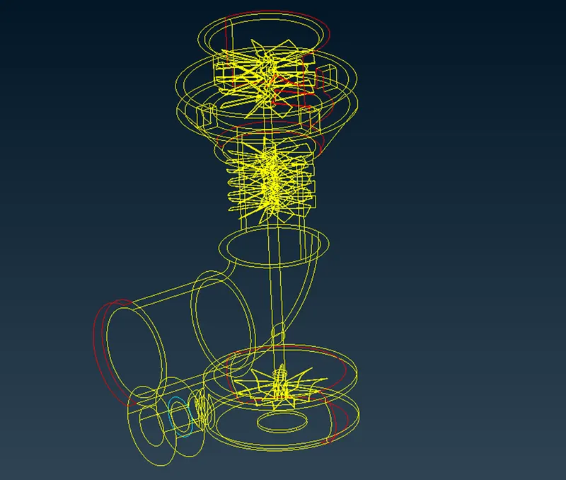
- Turbocharger cad model
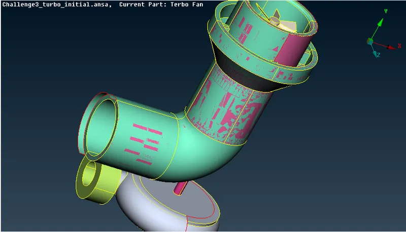
- Procedure
- Topo / Geometry clean up
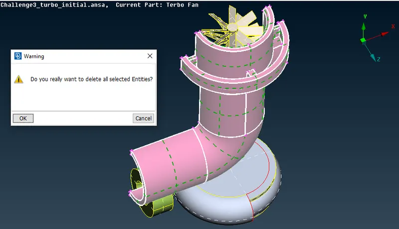
- Deleted Unwanted Surfaces
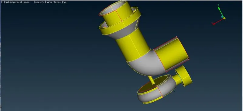
- Created new surface
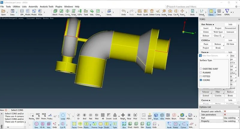
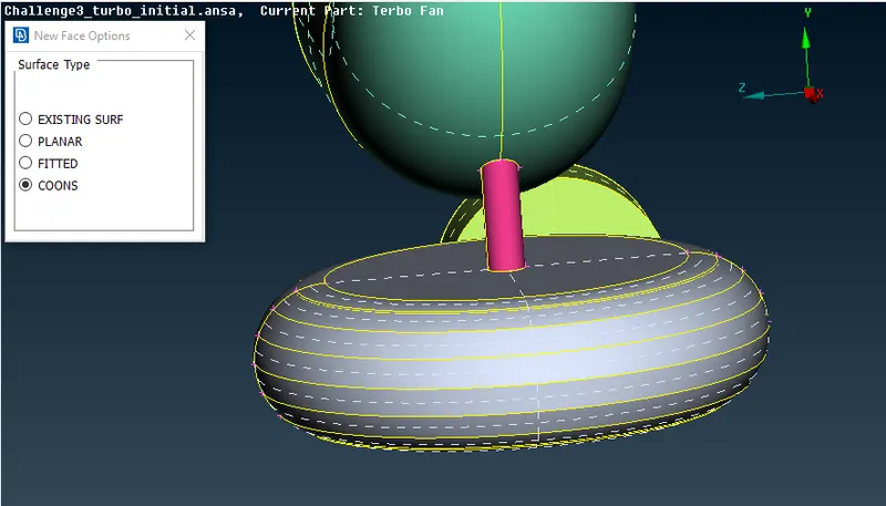
- Creating Surface -using parametric tool and coons
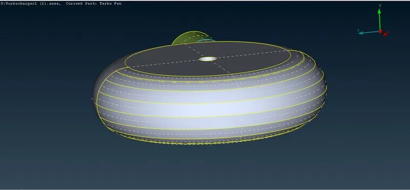
- Using intersect method to remove extra surface
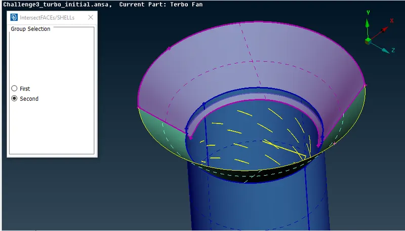
- Deleting overlapped surfaces
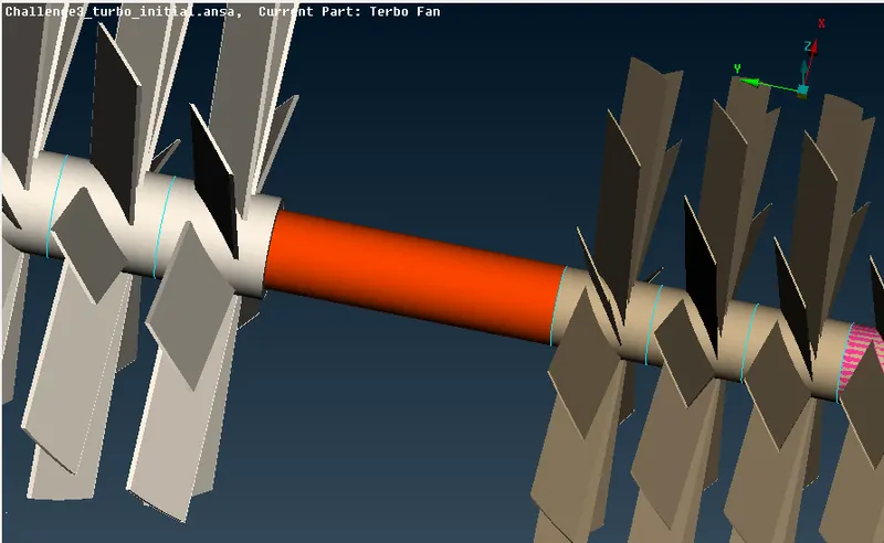
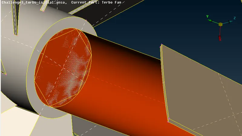
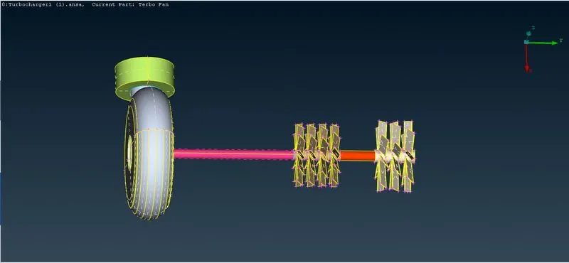
- Closed the open surfaces
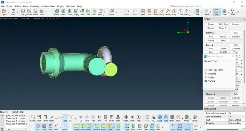
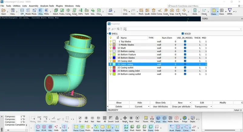
- Assigning the PIDs

- All PIDs are assigned
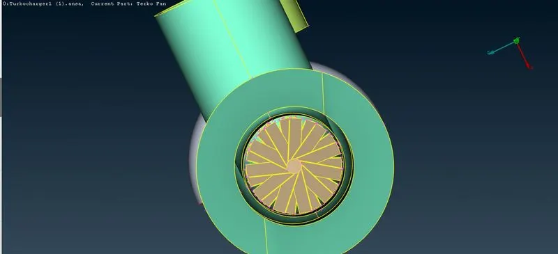
- Tripal cons are fixed
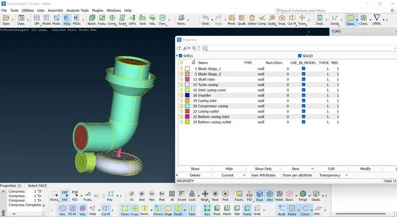
- New PID names are assigned
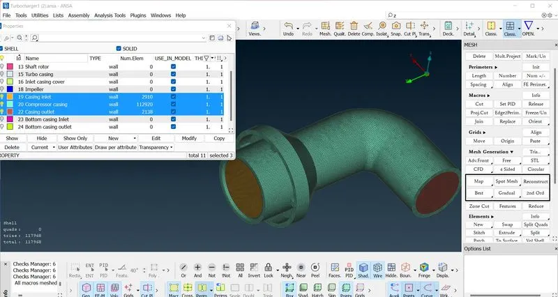
- Started with surface meshing
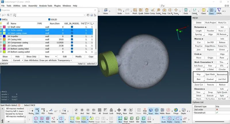
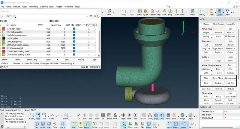
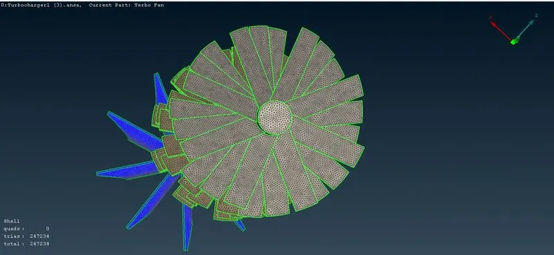
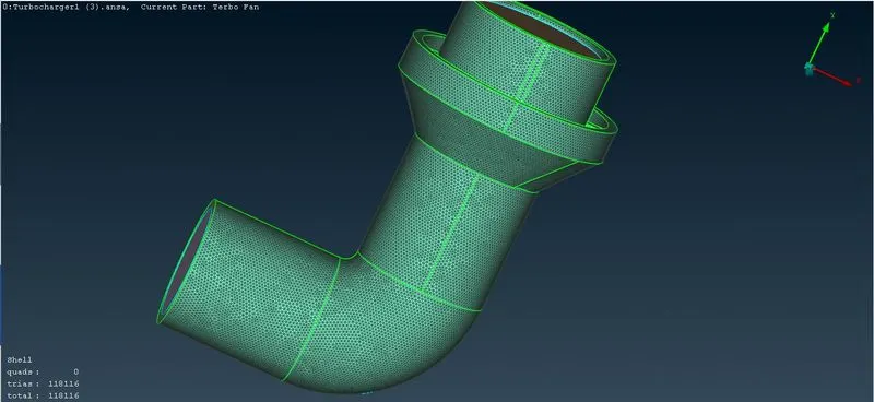
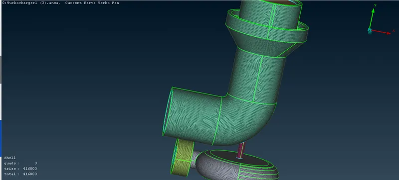
- Inner components meshing
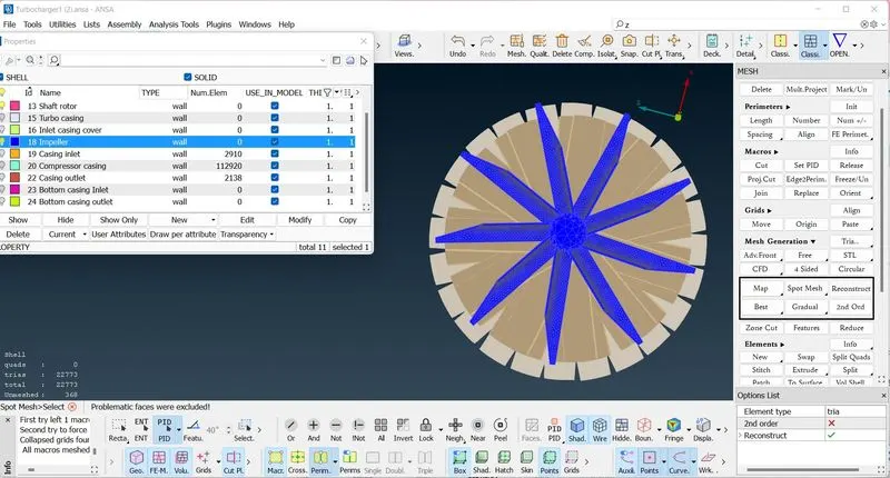
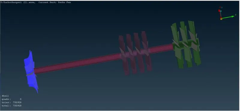
- Started with volumetric mesh
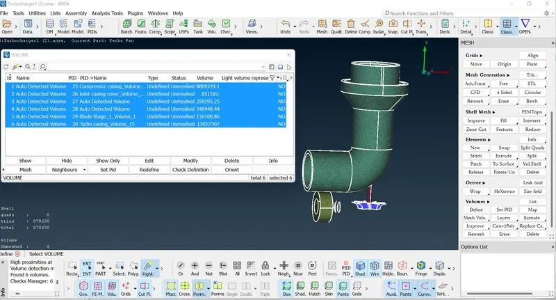
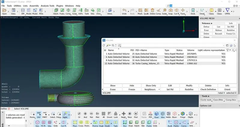
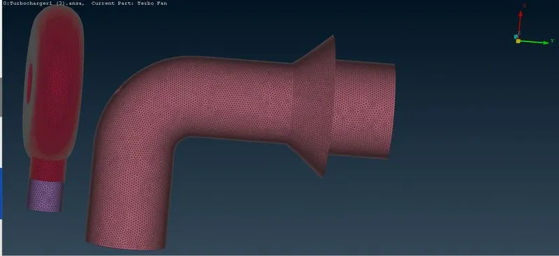
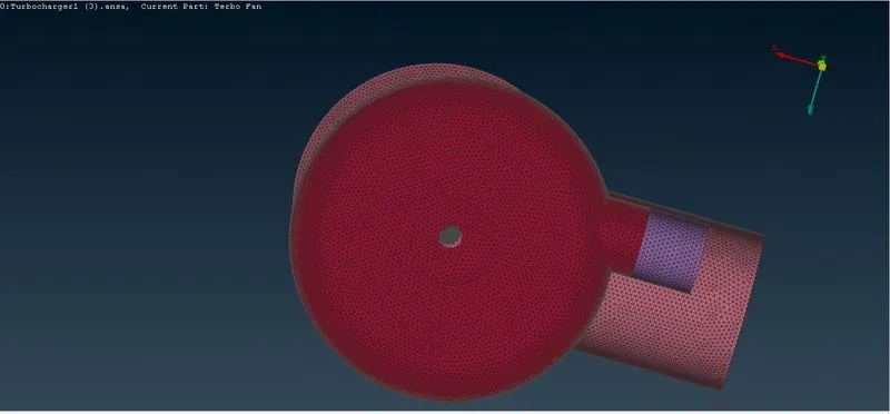
- Steps for Meshing
-
Topo/geometry cleanup:Load the ANSA file using the open option in the file drop-down list.
-
Start with a clean topo by doing a geometry check to find single and triple cons in the geometry. select topo under faces a box select the entire model to detect any missing cons and clean up the geometry more accurately.
-
Remove unnecessary overlapping surfaces using the universal removal option.
-
Start by filling the surface and removing individual disadvantages by creating a surface whenever needed. Some of the areas created with the new under faces option don't fit the surface we want, so some hot spots are projected so that small faces can be created and later joined to get the desired geometry.
-
Use the intersect option to remove a surface that has no separate entity, so using intersect creates a parallel entity that can be easily removed.
-
Single cons are solved, we can now focus on solving the triple cons that are present in the shaft area, because we need to have a single volume that facilitates meshing at a later stage. Remove overlapping surfaces to reduce them to double cons.
-
With the unnecessary triple negatives removed, we can now start naming each part by assigning it an individual PID.
-
After naming them, we can now move forward with the area meshing.
-
We need to mesh each component according to the given criteria in the question, so we need to mesh the component individually.
-
Enter the network quality and parameters and the network length for each component.
-
when entering the mesh length, be aware of the change of mesh length between components with different mesh length, when they come into contact, they tend to erase the other mesh, so when entering the perimeter and macros, we must enter a range from larger to smaller mesh length, so that the mesh does not erase.
-
After generating the mesh, we can create a boundary with varying mesh length and keep the mesh length constant on the other side of the boundary.
-
After completing the surface meshing, we can now achieve the volume meshing.
-
Under meshing volume select define and select whole db in the drop down window.
-
ANSA identifies the various volumes present in the geometry, we can delete the unwanted ones and leave the necessary volumes where the fluid can flow in the geometry.
-
After the mesh is newly created for each volume, the volume mesh can be displayed for each component.
- Conclusion
-
Achieved volume network of the turbocharger model.
- Learned about more complex tools for cleaning up geometry and creating geometry suitable for meshing.
Volume mesh created -
Different mesh size tends to cause errors in the contact areas of 2 areas with different mesh lengths, so the mesh range can be specified to prevent the mesh from being erased.
- TETRA, CFD and free mesh algorithms were utilised for meshing.