Week 3 Challenge : CFD meshing on Turbocharger
Aim-To create volumetric meshing of a turbocharger model using different element sizes for different PIDs using ANSA.
Objectives:
1. Create surface meshing of the turbocharger model.
2. Assign different PIDs as per convenience.
3. Create volumetric meshing of the turbocharger model.
Procedure-
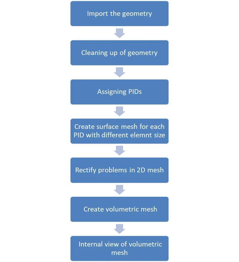
The process of creating volumetric mesh of a turbocharger starting from geometric clean-up has been demonstrated in the figure below.
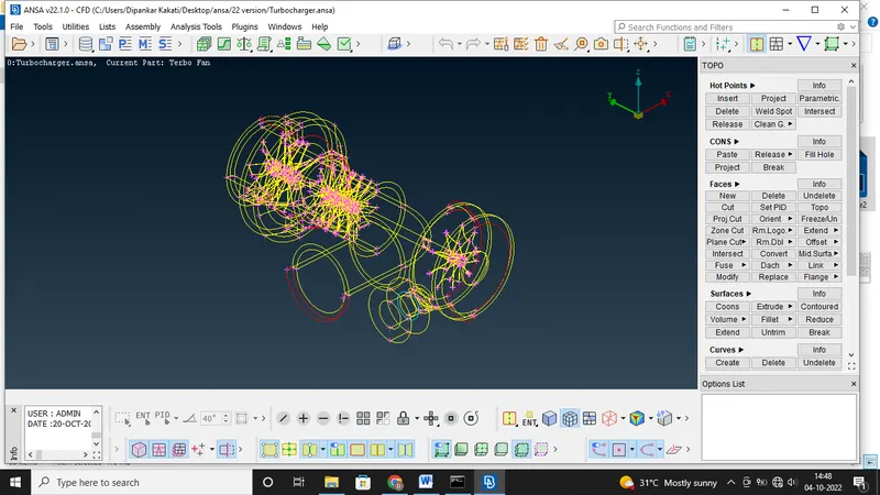
After importing the turbocharger model, we have to go for geometric clean up. The errors are identified by single cons and triple cons on the surfaces. We have to Check ON in visualizing the CONS to identify where the single CONS are in the Process Parameters on the Quality Criteria. The errors can be rectified by deleting unnecessary surfaces, overlapping surfaces, creating new faces or filling holes.
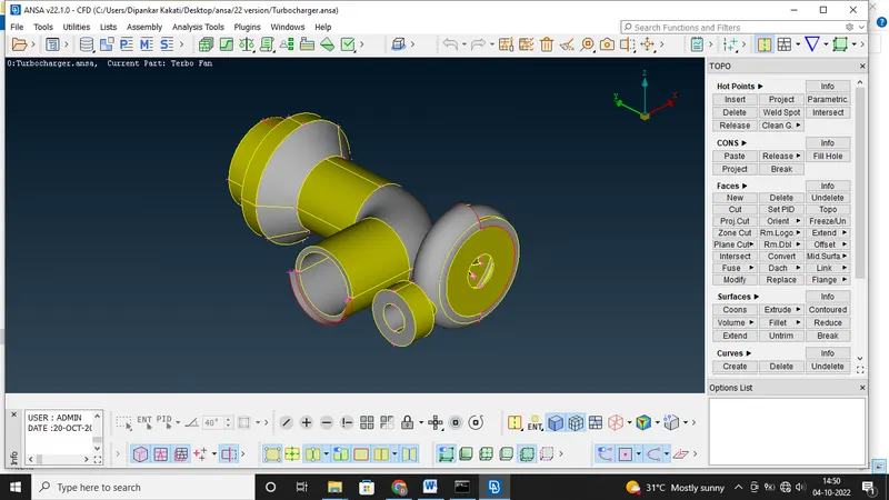
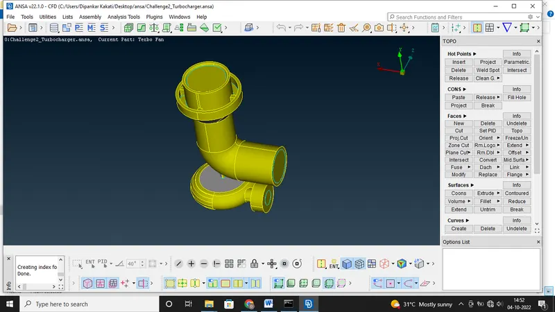
Then the next phase is to assigning the Property IDs (PIDs). This is used to differentiate each component with different names and colors and to perform different meshes too. The bulb in the selected PID is glow based on whether the selected PID is visible or not. For the invisible inner components, the bulb will not glow. Latterly, the Compress option is used to view only the visible components in the model. This option generally simplifies the model by not showing the invisible components. The most important to know about the compressor option is, once compression is done, we cannot retrieve those components in the model.
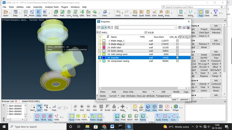
AFter assigning PIDs, generate surface mesh for each PID using different element size as shown below-
- Blade stage-1 = 1 mm
- Blade stage-2 = 1 mm
- Impeller = 2 mm
- Shaft rotor = 1 mm
- Turbo casing = 5 mm
- Compressor casing = 5 mm
- Inlet casing cover = 5 mm
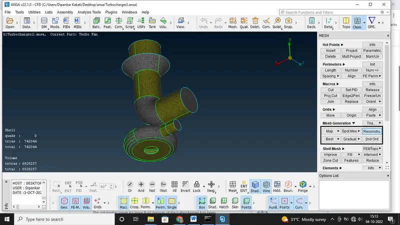
As per the above-mentioned node lengths, we are going to assign individual node lengths for each individual PID. Now go for surface meshing. Assign Mesh parameters, Quality criteria, lengths ( perimeter and macros). Also, this model has different mesh lengths respective to different parts. If two edges are in contact with each other and having different mesh lenghts then some mesh is removed from a particular surface. Then again assign mesh length on vanished area present on the model and while assigning the lengths allow the ANSA software to choose range of mesh length accordingly. It will show range of particular mesh lengths. This is why because it selects the common circumference of two different parts. In order to isolate region where there is change in mesh length was present use cut options from Macros with reconstruct option enable.
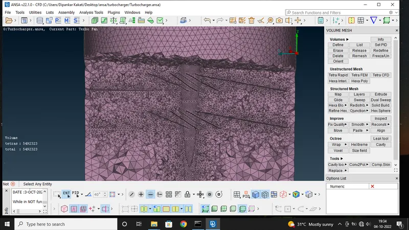
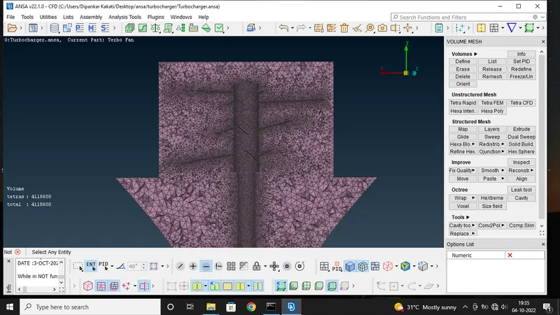
For volumetric meshing, go to the vol.mesh deck. go to volumes then auto detect option then select whole database then ANSA will auto detects and shows us different volumes list which is to be meshed. After detecting the volumes from the geometry select the required volumes and delete the unwanted ones. Now performing volumetric mesh using the command: unstructered mesh-tetra CFD in the v-mesh module. After volume mesh when disecting the turbocharger using NOT command we see that inside the turbocharger there is a perfect creation of volume which is created inside and around the blades and shaft in the turbocharger.
Conclusion:
The volumetric mesh for inner fluid domain of the turbocharger has been performed.
- 742044 tria elements (2D-element) have been bonded to form a surface mesh over the geometry.
- 6928257 tetra elements (3D-element) have been bonded to form a volume mesh inside the geometry
The google drive link for the turbocharger meshing is given below-
https://drive.google.com/file/d/1sFJZBYarom3V3d5QU_WSYYGhv3J-MXpS/view?usp=sharing