Week 3 Challenge : CFD meshing on Turbocharger
What is function of a turbocharger?
Turbochargers are used to perform compression on the air that it is coming in towards the engine cylinder. Due to its function, the fuel efficiency of the engine is increased. It has the parts such as compressor, impellor, rotor shaft and two different stages of blades.
OBJECTIVE
-To check for the geometrical errors to make appropriate volumes in the given model
-To create and assign PIDs as shown in the video. Perform surface mesh with the given target lengths as per PIDs.
- Blade stage-1 = 1 mm
- Blade stage-2 = 1 mm
- Impeller = 2 mm
- Shaft rotor = 1 mm
- Turbo casing = 5 mm
- Compressor casing = 5 mm
- Inlet casing cover = 5 mm
-To perform Volumetric mesh for the required volumes and write a detailed report on your surface meshing & Volume meshing process.
PROCEDURE AND RESULTS
A. GEOMETRY CLEANUP
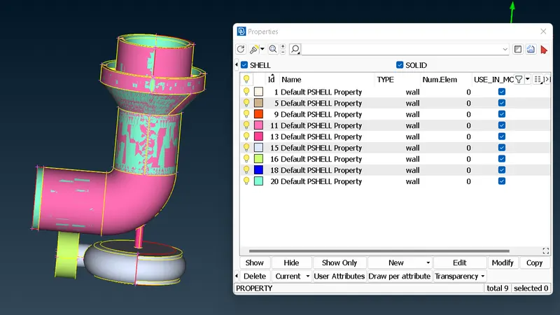
Step 1: Loading the file and checking the pre-assigned PIDs of the turbocharger
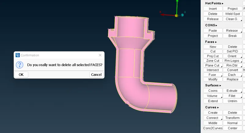
Step 2: Isolate the unnecessary face from the figure and delete it (PID mode)
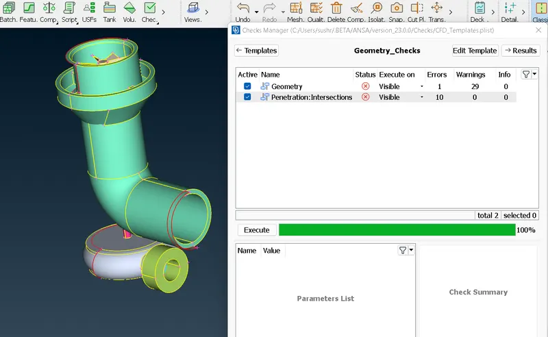
Step 3: Performing Geometrical Check of the entire figure to identify errors
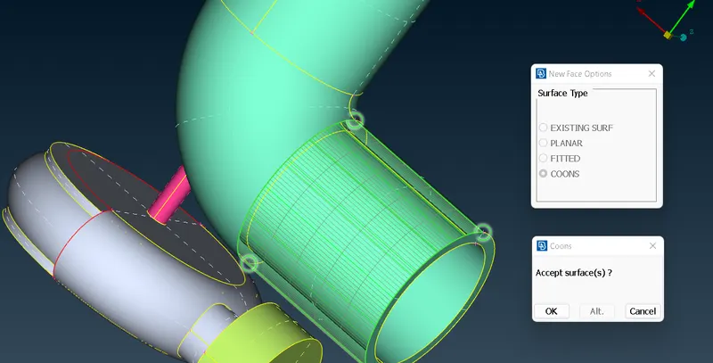
Step 4: Correcting the Single CONS errors
Step 5: Intersecting the necessary pair of FACEs
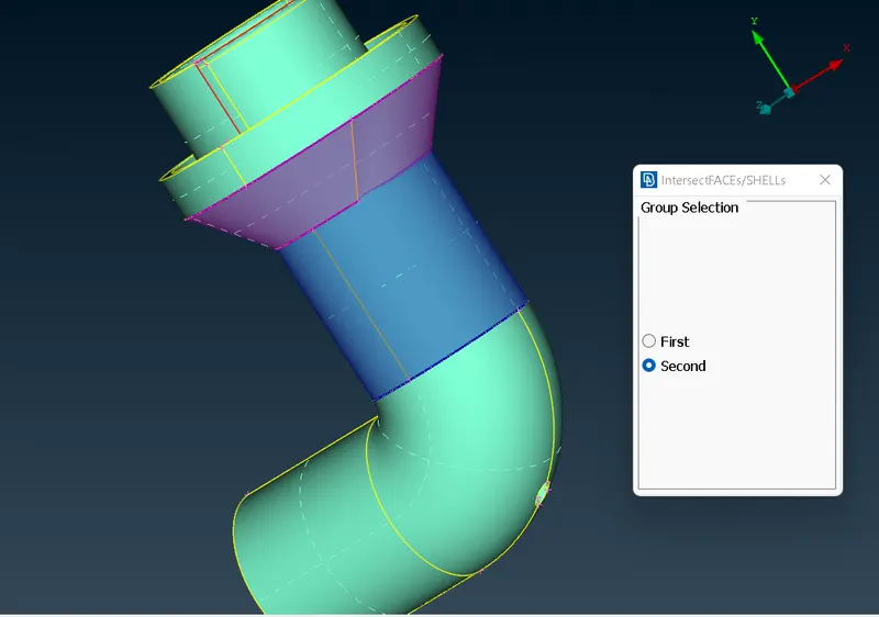
Step 6: Keeping the necessary FACEs and Deleting the unnecessary ones
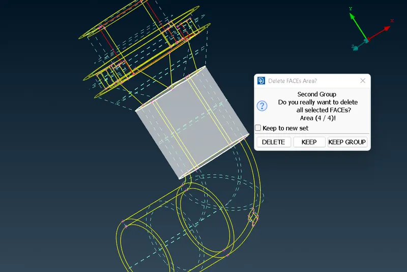
Step 7: Using TRANSFORM over curved surfaces to generate a boundary for FACE creation
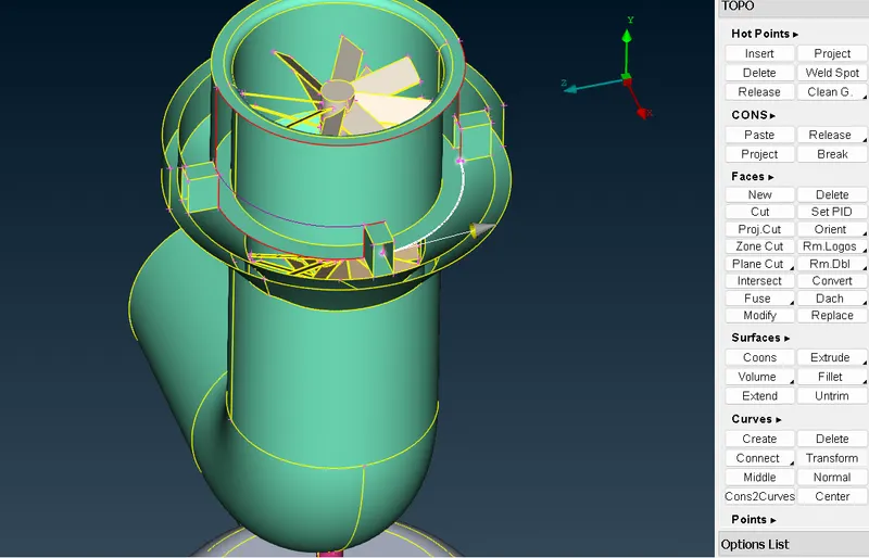
Step 8: Creating FACEs based on temporary boundaries
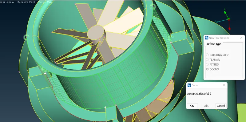
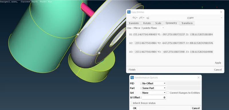
Step 9: Removing Single CONS error from Inlet casing cover using "MIRROR 3-point plane" in the "Transform" option
(Transform>Copy>Entities>Selection of Entities>Scroll Click>Selection of Three points plane>OK>Finish)
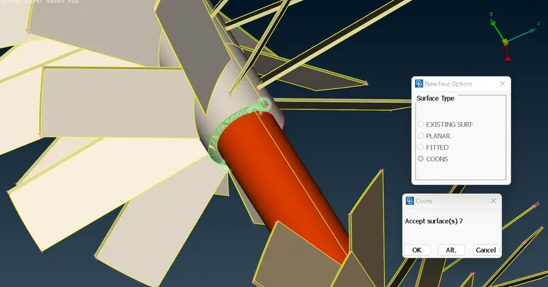
Step 10: Creating missing surface
Step 11: Removing Triple CONS from the geometry
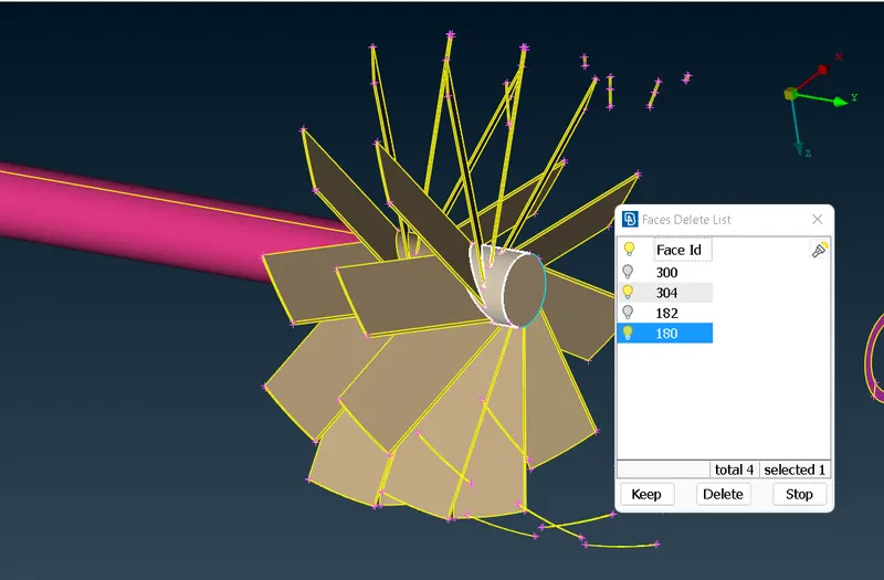
Step 12: Deleting overlapping areas to get rid of Intersection errors
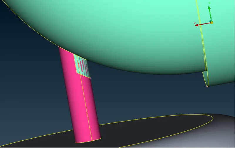
Step 13: Using "Project" options to remove SINGLE CONS error appearing after removing "Intersection" errors
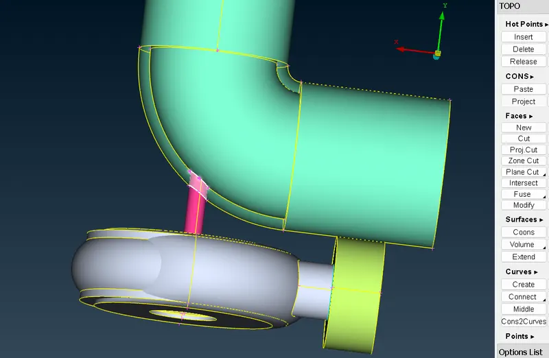
Step 14: Using CONS "Project" option to remove SINGLE CONS of the projected areas
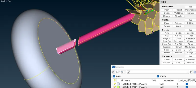
Step 15: Deleting unnecessary surfaces causing "Intersection" errors
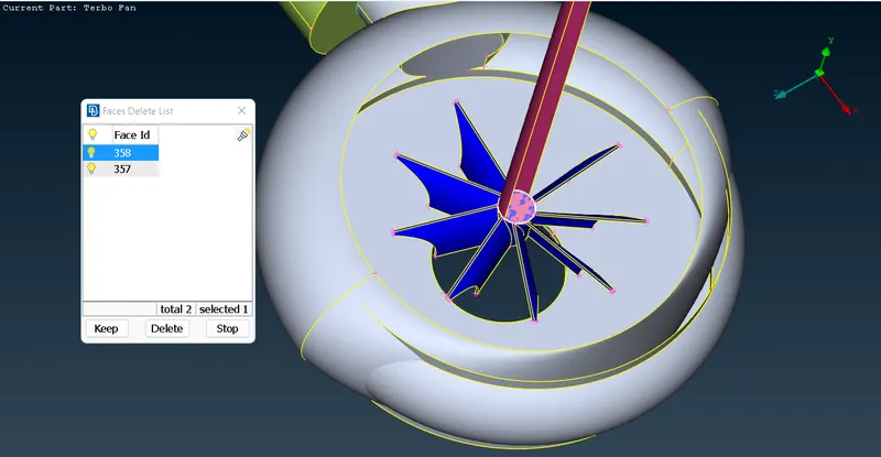
Step 16: Using "Project" for making surface available for delete while dealing with "Intersection" errors
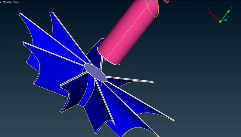
Step 17: Final Geometry Checking before meshing process
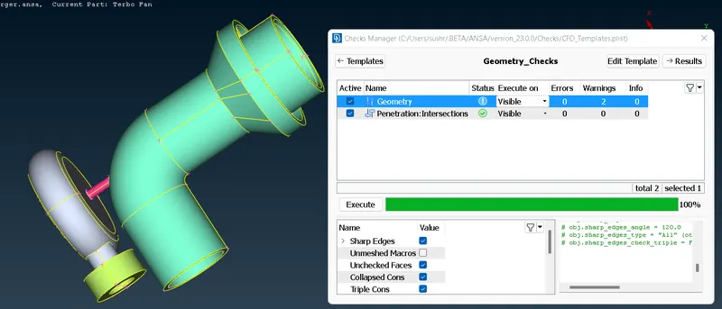
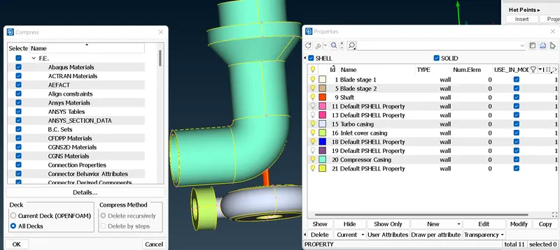
B. CREATING AND ASSIGNING PIDs
Step 18: Assigning names to necessary PIDs and compressing the unnecessary ones
C. SURFACE MESHING
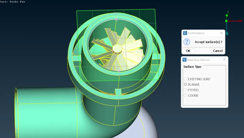
Step 19: Closing the open faces before performing meshing
Step 20: Setting mesh parameters for the compressor casing (target length - 5 mm)
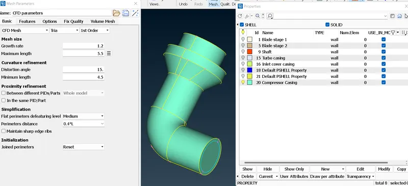
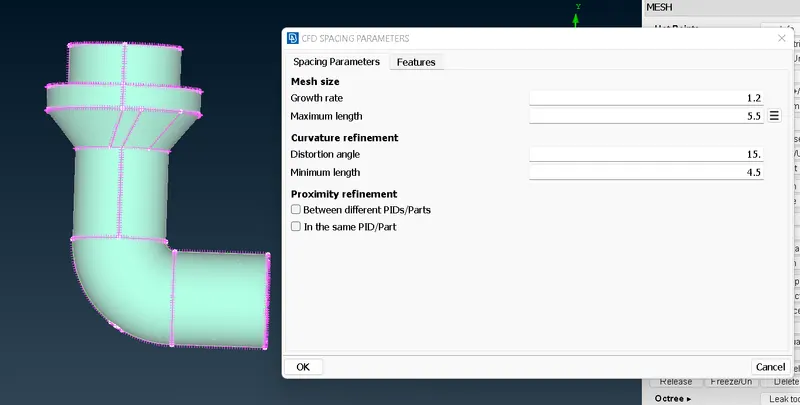
Step 21: Setting up CFD spacing parameters (perimeter and macros) - Surface meshing
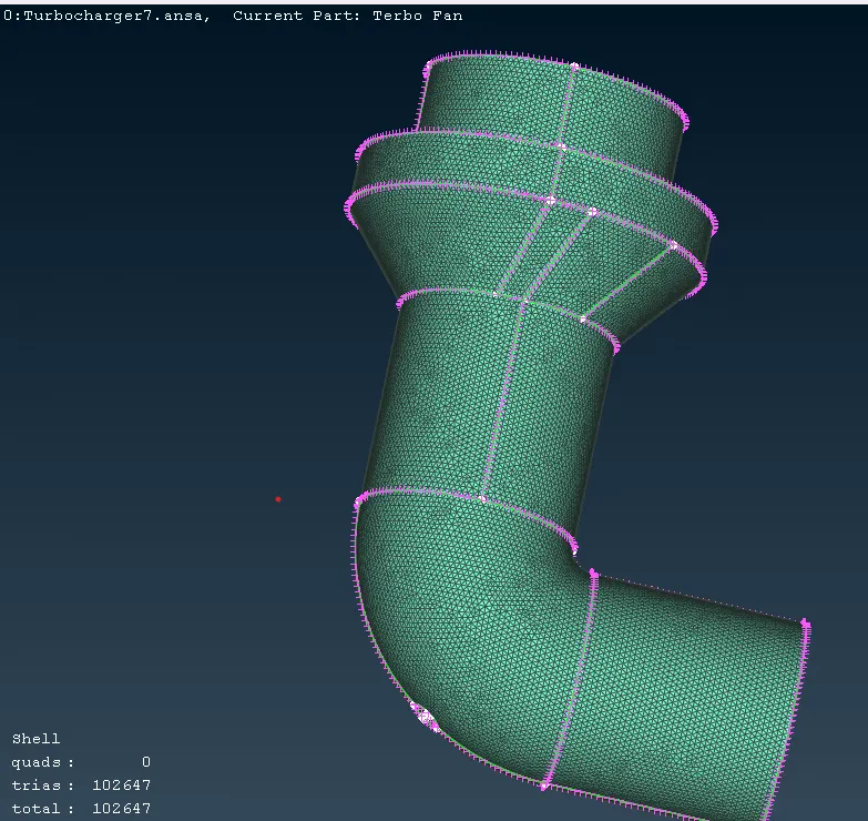
Step 22: Meshed surface of compressor casing (5 mm)
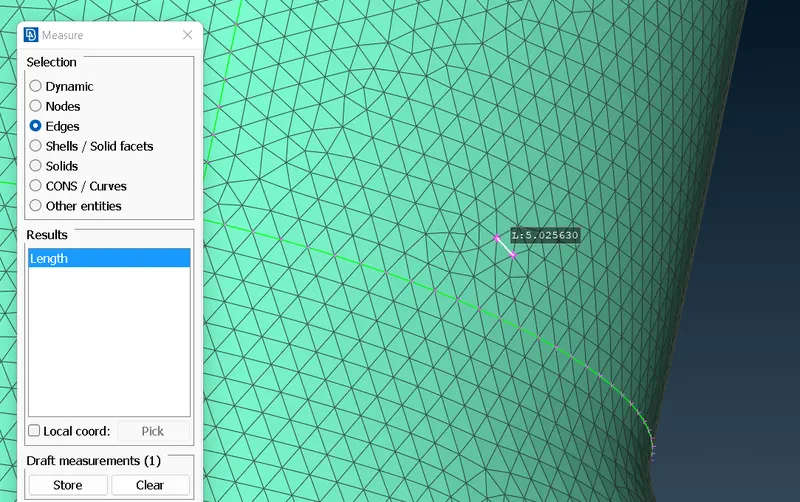
Step 23: Measuring the node after meshing
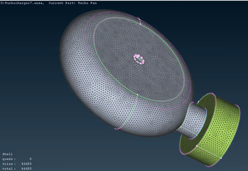
Step 24: Meshed surface of turbo casing and inlet cover casing (5 mm each)
 S
S
Step 25: Meshed surface of impeller (2 mm)
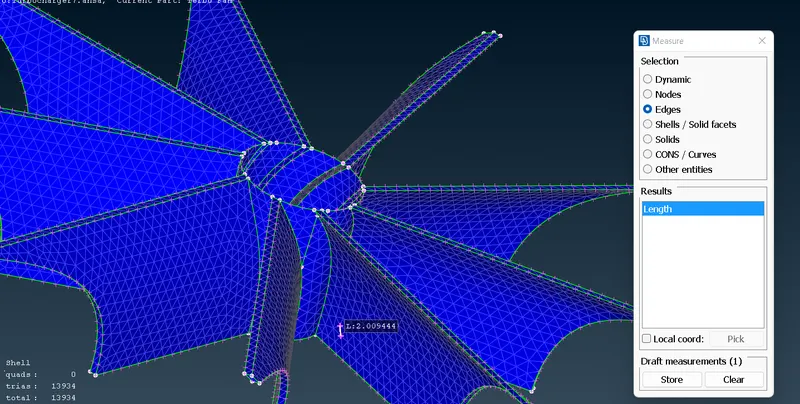
Step 26: Meshed surface of Blade stage 1, Blade stage 2 and Shaft rotor (1 mm)
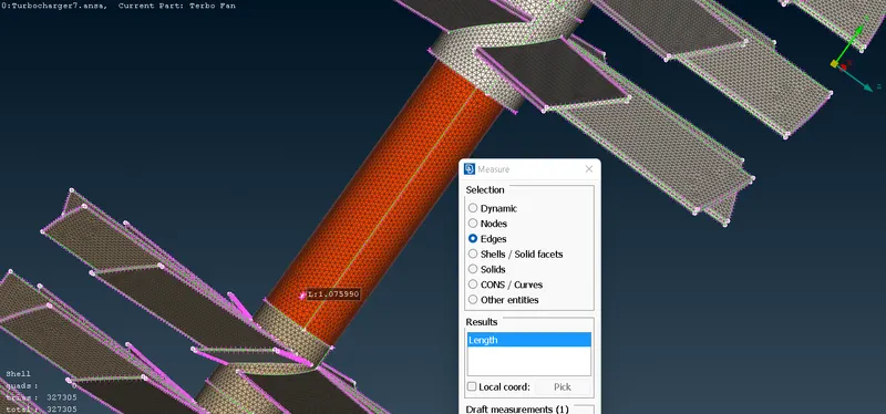
Step 27: Using 'Freeze" over each PID to get rid of unmeshed elements
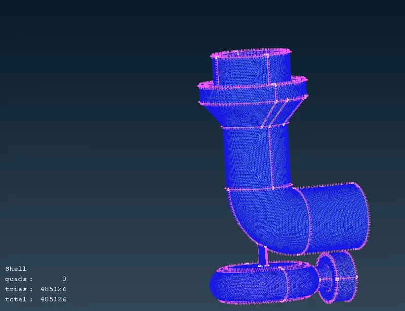
D. VOLUME MESHING
Step 28: Changing the mesh type to "Tetra CFD"
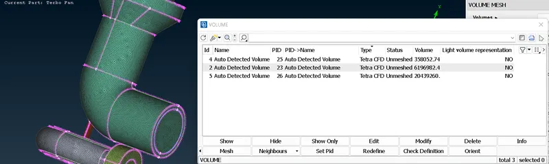
Step 29: Performing Volume Mesh on the defined unmeshed volume
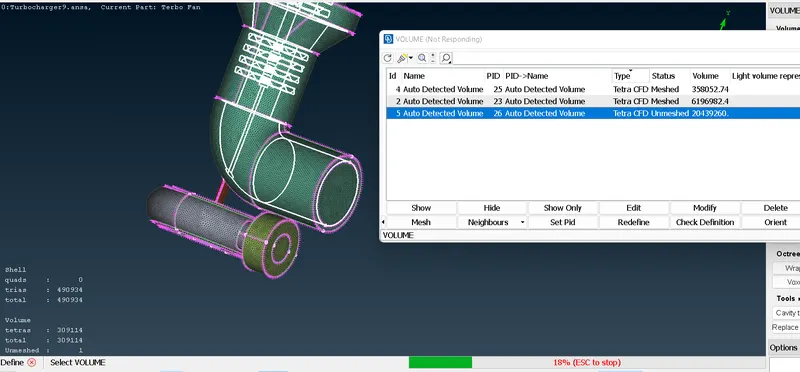
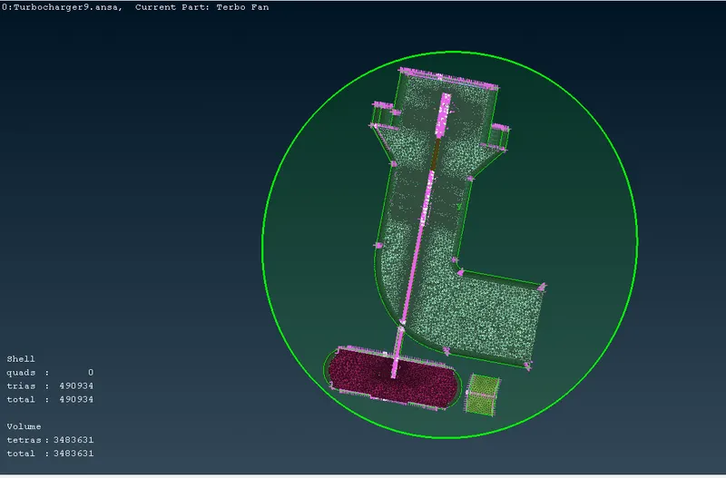
Step 30: Checking the volume mesh with "Cut Plane" option along "X-Y plane"
CONCLUSION
-The turbocharger model has been attached with the necessary surface meshing and volume meshing criteria
-The challenge exposed us to the process of volume meshing and using elements such as "TETRA CFD"
-The challenge helped to explore different methods of geometry cleanup
-The challenge helped to deal with penetration errors and warnings
-The challenge was completed by approaching INTERNAL VOLUME MESHING of the given turbocharger model
(Geometry file attached below)
GOOGLE DRIVE LINK OF THE FILE
https://drive.google.com/file/d/1DZQYF1x8BUX0MIrc3WI-qGdXYE5N0QD9/view?usp=sharing