Week 2 Challenge : Surface meshing on a Pressure valve
What is a pressure valve?
A pressure valve (or a pressure relief valve) is used to discharge fluids when the pressure in the system reaches a pre-determined "set pressure". The reason behind using pressure valves is to release the excess pressure within the system in order to prevent damage and failure of the pressure vessels. It mainly acts as a safety device.
AIM
-To check for the geometrical errors and perform Topology cleanup
-To set three different target lengths as three different cases and mesh the model.
- Target length = 1mm, 3 mm and 5 mm (i.e. 3 cases)
- Element type = Tria
PROCEDURE
Step 1: The given file is downloaded and opened in ANSA. The file is visible in "SHADOW" mode.
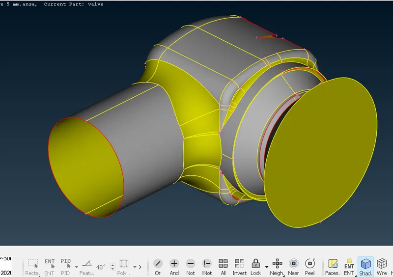
Step 2: Checking the errors or CONS in the file by enabling the "WIREFRAME" mode.
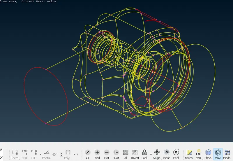
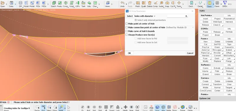
Step 3: Enabling the "PID" mode and eliminating the SINGLE CONS (Red CONS) by "Fill Hole" option
(TOPO deck > CONS > Fill Hole > OK)
Step 4: Eliminating remaining SINGLE CONS errors with other "NEW FACE' generation options
A. (TOPO deck > Faces > New > PLANAR > Selection of SINGLE CONS > Scroll click > OK)
B. (TOPO deck > Faces > New > FITTED > Selection of SINGLE CONS > Scroll click > OK)
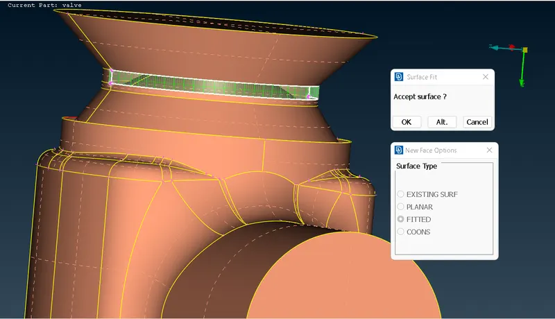
C. (TOPO deck > Faces > New > COONS > Loop > Selection of SINGLE CONS connected surface > Scroll click > OK)
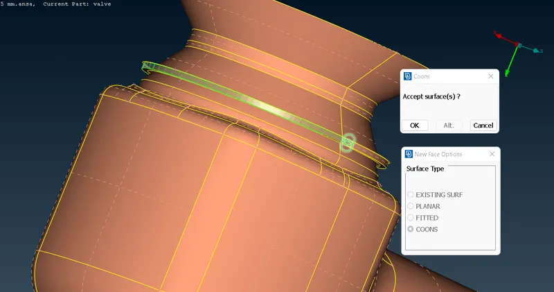
D. (TOPO deck > Faces > New > COONS > Selection of "ENT" (Entity) mode > Selection of SINGLE CONS connected surface (one by one) > Scroll click > OK)

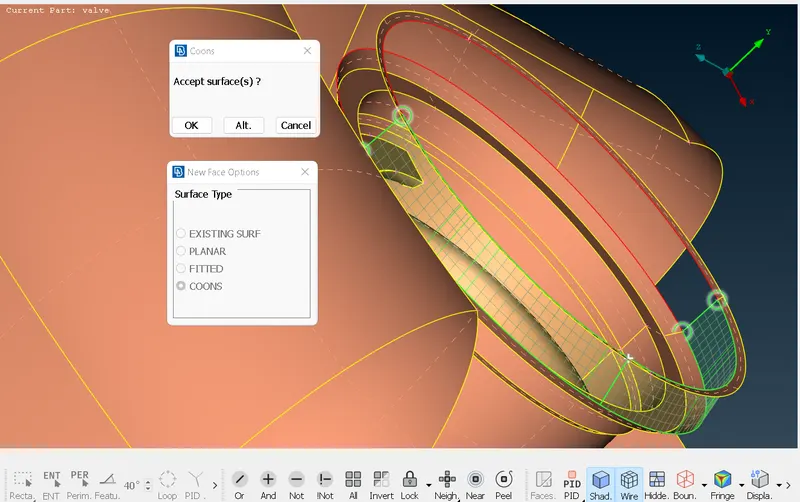
E. (TOPO deck > Faces > New > COONS > Loop > Selection of SINGLE CONS connected surface > Scroll click > OK)
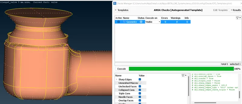
Step 5: Checking for "Geometry" errors using Checks Manager
(Checks > Checks Manager > Templates > Geometry Checks > Execute)
Step 6: Checking for "Intersection" errors using Checks Manager
(Checks > Checks Manager > Templates > Geometry Checks > Execute > Penetration:Intersections > Selection of errors)
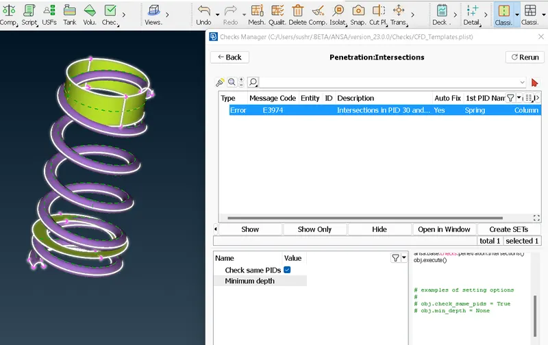
Step 7: Elimination of "Intersection" errors
(TOPO deck > Intersect > Selection of first surface > Selection of second surface > Either deletion or keeping of FACEs)
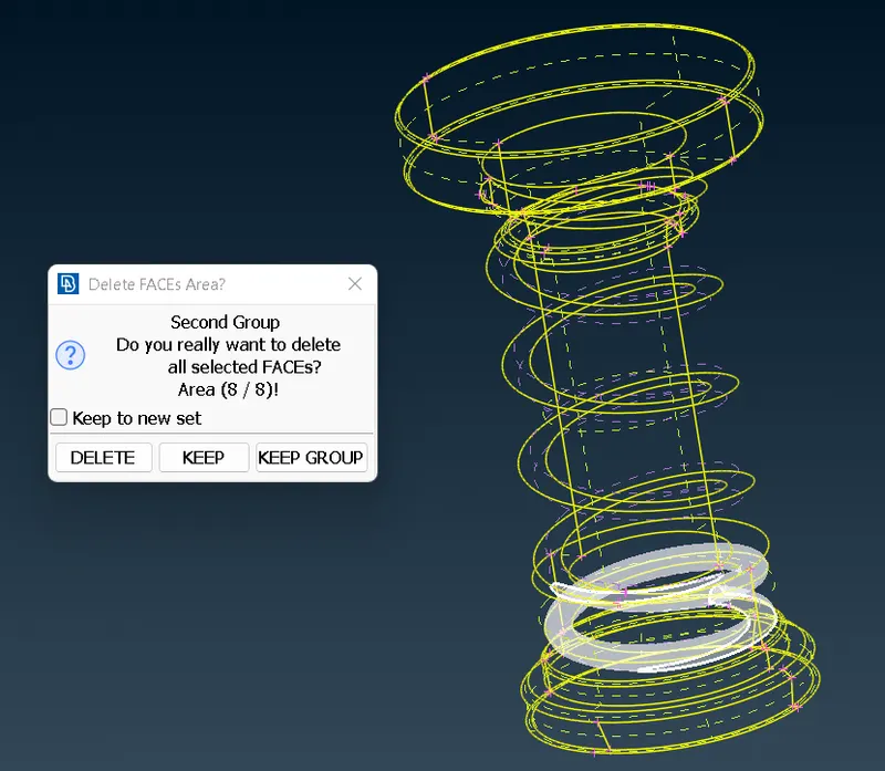
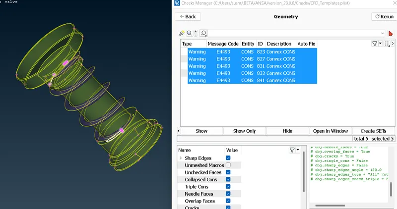
Step 8: Rechecking the "Geometry" and "Intersection" errors and ignoring the warnings originated due to figure geometry
(Checks > Checks Manager > Templates > Geometry Checks > Execute > Penetration:Intersections > Selection of warnings)
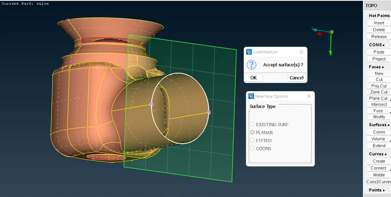
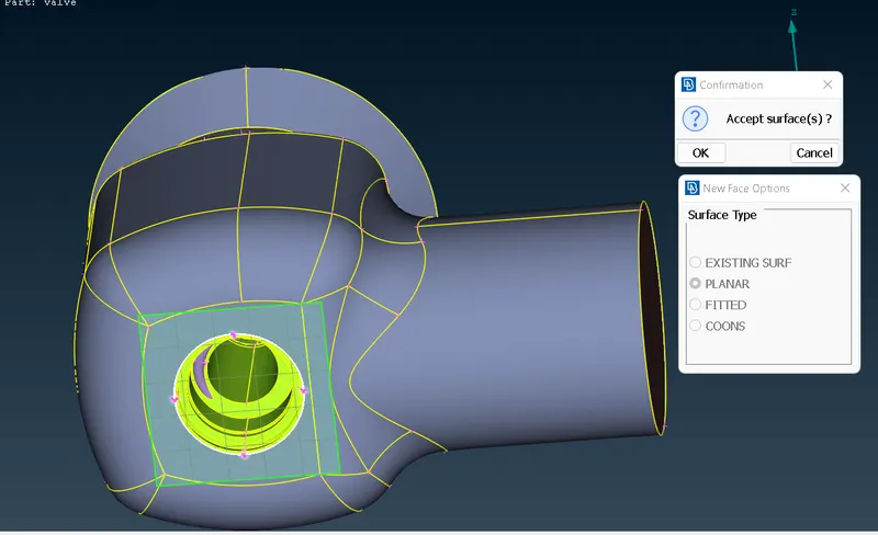
Step 9: Adding faces to hollow areas as a prerequisite of mesh generation process
(TOPO deck > Faces > New > PLANAR > Accept surface > OK)
Step 10: Setting up the Mesh parameters (using CFD mesh)
A. (Mesh > Basic > General > Target length - 5 > OK)
B. (Mesh deck > Perimeters > Spacing > Auto CFD > Selection of Perimeter and Macros > Scroll click > CFD spacing parameters > Maximum length - 5.5 > Minimum length - 4.5 > OK)
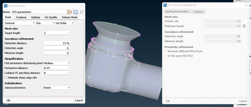
Step 11: Setting up the Mesh parameters (using CFD mesh) and measuring the node distance to ascertain mesh size
(5 mm) - [FILE NO. 1]
(Measure > Nodes > Selection of two nodes)
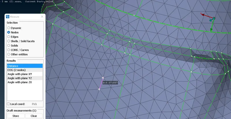
Step 12: Setting up the Mesh parameters (using CFD mesh)and measuring the edge distance to ascertain mesh size
(3 mm) - [FILE NO. 2]
A. (Mesh > Basic > General > Target length - 3 > OK)
B. (Mesh deck > Perimeters > Spacing > Auto CFD > Selection of Perimeter and Macros > Scroll click > CFD spacing parameters > Maximum length - 4 > Minimum length - 2 > OK)
C. (Measure > Edges > Selection of one edge)
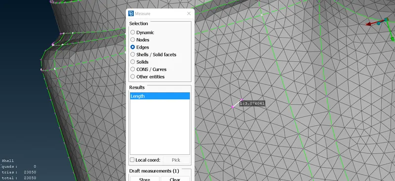
Step 13: Setting up the Mesh parameters (using CFD mesh) and measuring the node distance to ascertain mesh size
(1 mm) - [FILE NO. 3]
A. (Mesh > Basic > General > Target length - 1 > OK)
B. (Mesh deck > Perimeters > Spacing > Auto CFD > Selection of Perimeter and Macros > Scroll click > CFD spacing parameters > Maximum length - 1.5 > Minimum length - 0.7 > OK)
C. (Measure > Edges > Selection of one edge)
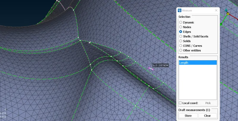
RESULTS
* 3 separate files of ".ANSA" extension have been generated that contain the surface mesh of given pressure valve with target length 5 mm, 3 mm and 1 mm respectively.
CONCLUSION
- The challenge exposed us to the process of checking for geometrical errors in the given model of pressure valve
- The challenge required to perform topology cleanup for preparing the model for CFD meshing
- The challenge exposed us to the process of assigning PIDs (Property ID) to each component in the model
- The challenge exposed us to the process of using "Lock" feature of ANSA while working on individual component
- The challenge helped us to identify and eliminate "Penetration:Intersection" errors from the model
- In the present challenge, 3 separate target lengths (1 mm, 3 mm and 5 mm) have been used for meshing along with varying "minimum length" and "maximum length" accordingly
- 3 separate ANSA files have been uploaded along with detailed discussion of the procedure, tools and result to complete the report of the given challenge