Week 3 Challenge : CFD meshing on Turbocharger
Aim/Objective: To get through the lessons learned in live class for Week 3 and go ahead to complete the Week 3 challenge with the required format for the report.
The procedure, Learning Outcomes, Result, and Conclusion. Also, the report should have images if required while discussing steps or results, or conclusions.
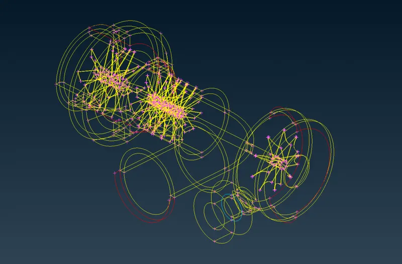
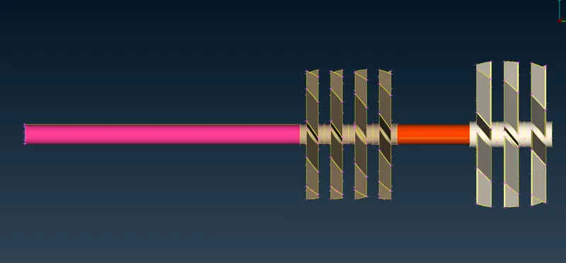
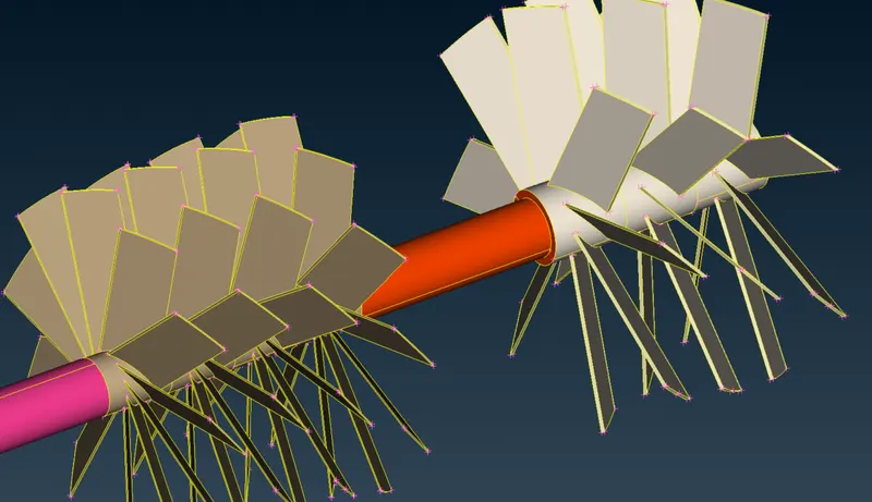
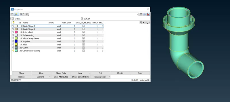
This is the Turbocharger model which we have
Show labels
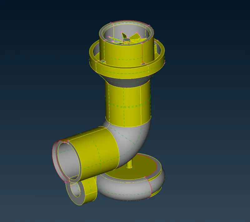
What is Turbocharger:
The engine exhaust gases go to the inlet and that energy is converted into kinetic energy through blades. The compressor intakes air and gets fresh Oxygen for more combustion.
Let's start
We can see multiple errors:
Let's change this in PID mode:
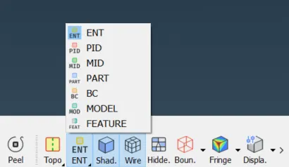
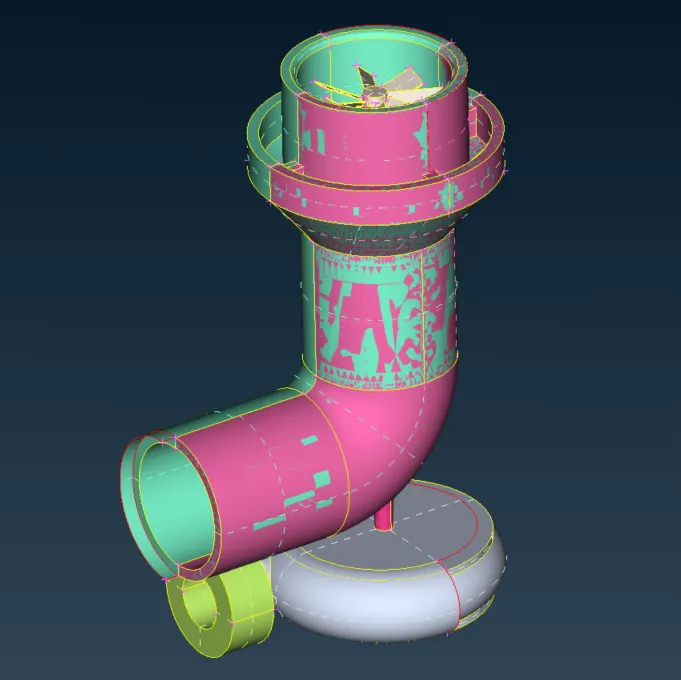
Enabling the PID mode we can see this.
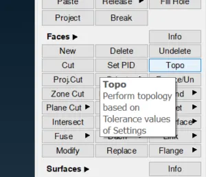
We don't need to change the resolution as the geometry is clear, so let's start with the Basics, Doing TOPO.
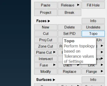
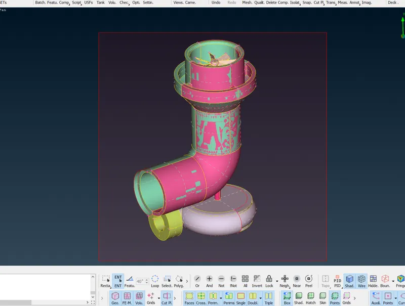
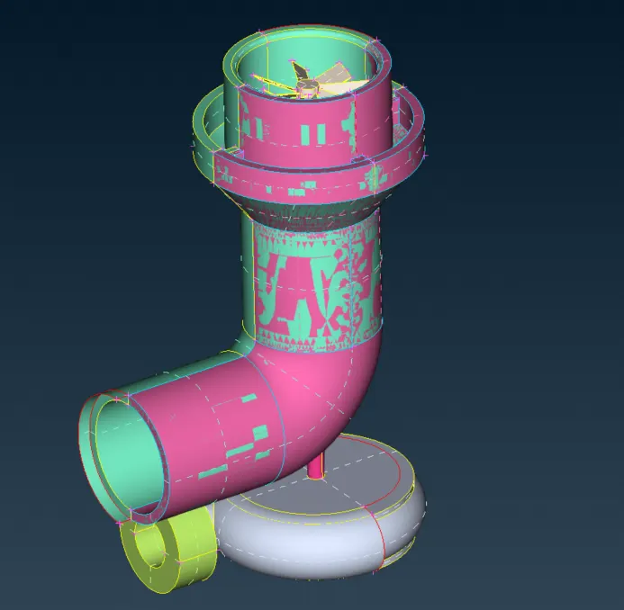
Some minor changes have been done like some blue cons have been generated.
IN PIDs mode we can just suppress some PIDs 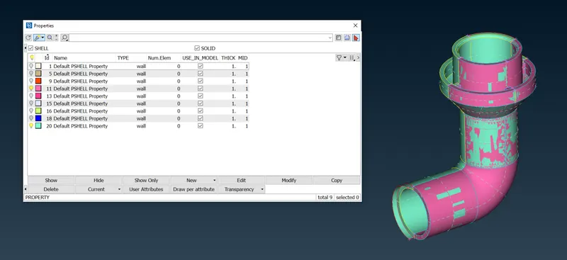
Let's just take Pink and green for instance
try hiding pink
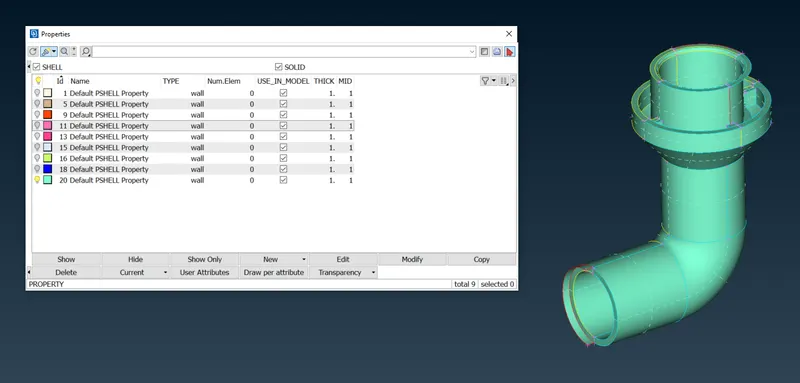
Only pink visible
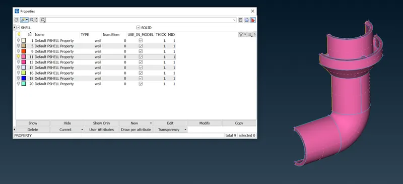
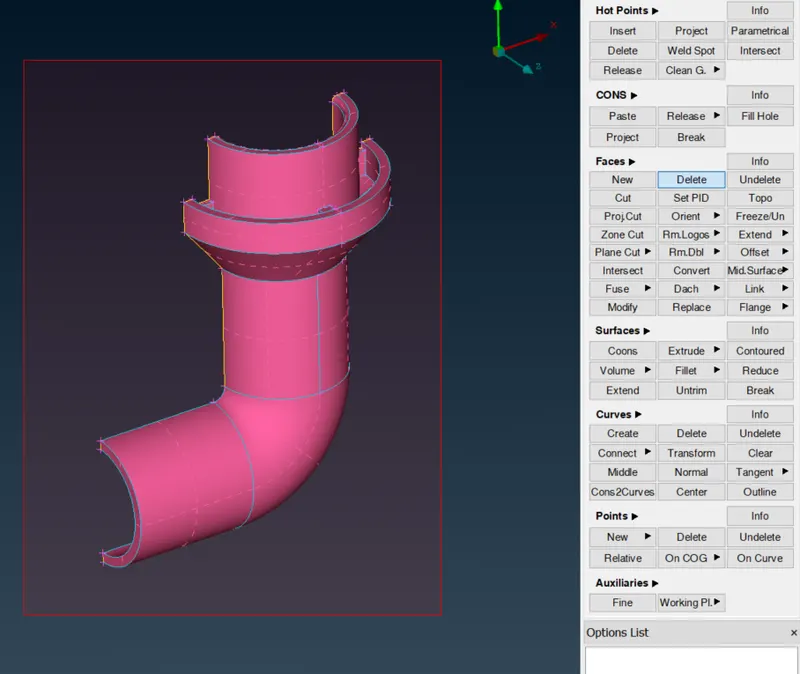
We can delete the undesired part of the Light Pink color as that is the merging part which is of no use in this geometry.
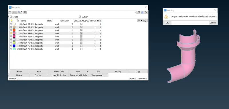
We will use the 'Universal Delete' option for getting this face deleted.
Let's switch on the Green body part, and check the cross hatches.
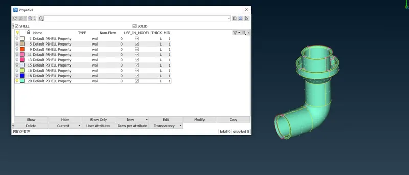
Let's compress the unused layer in the table of PIDs
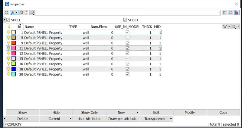
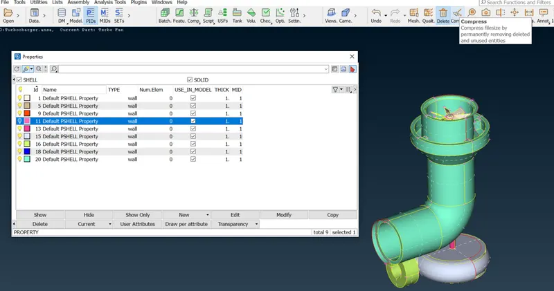
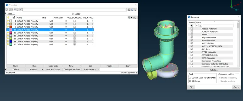
on compression, we have this
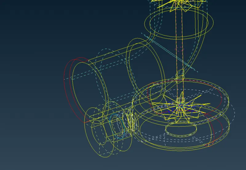
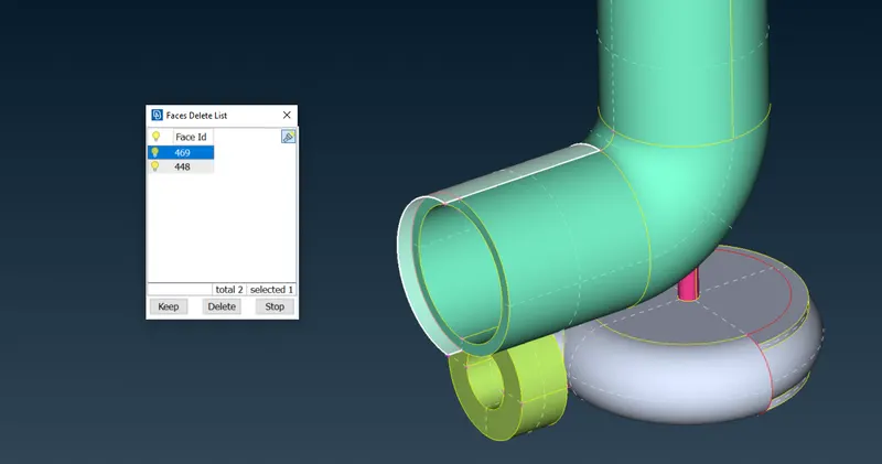
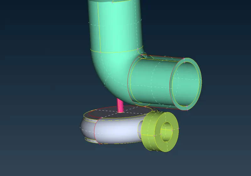
Use the loop method of selection for selecting the complete loop
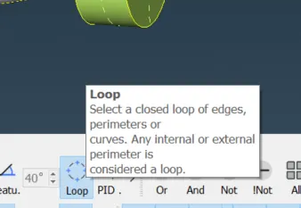
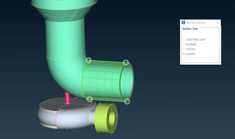
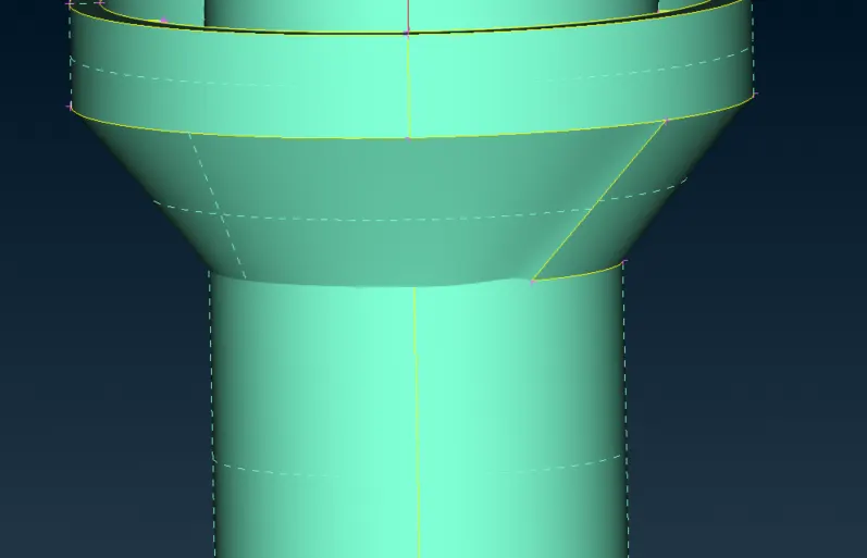
The intersection we are doing to?
create distinct boundaries, make boundaries and eliminate unnecessary surfaces.
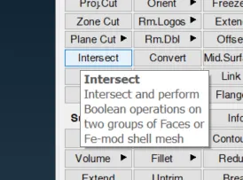
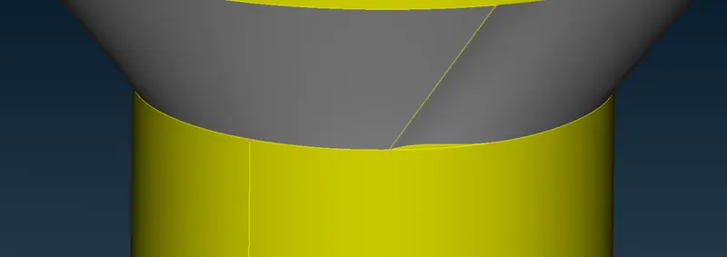
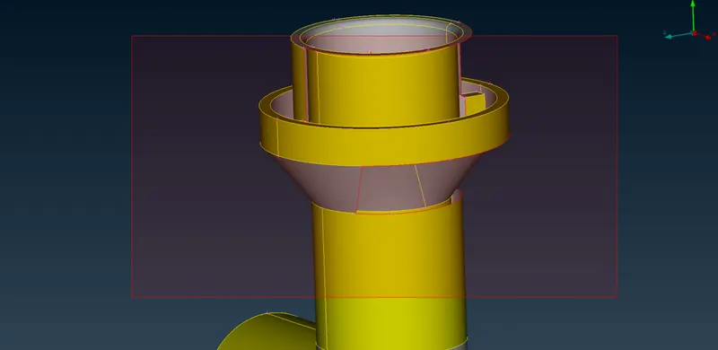
We have removed the part which is not of our use for the removal of the red CON
Removing the non-used area of components by using the NOT function and locking the part.
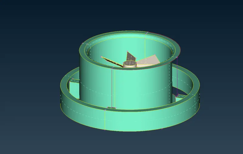
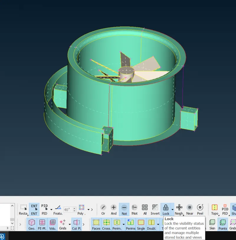
We checked by making curves and cannot make the surface as per requirement. We can see in this image below:
Even on using COONS method we are getting this curve:
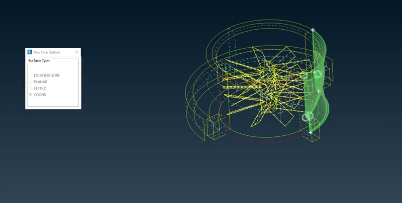
which is not acceptable for us so we will now learn a new TOOL.
"Transform"
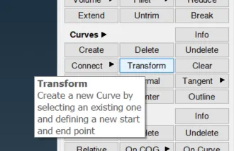
We have to select two reference points to make a curved surface by using this tool.
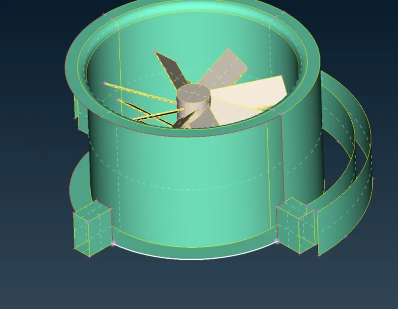
Selecting the edge and doing a left click
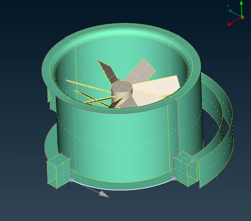
It shows the direction
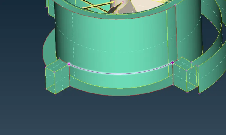
We use two points for this and the curve is projected as seen in the above image.
We should be following the same direction of the arrow for the points selection so that is why we need to select in the same directional way.
Let's move forward.
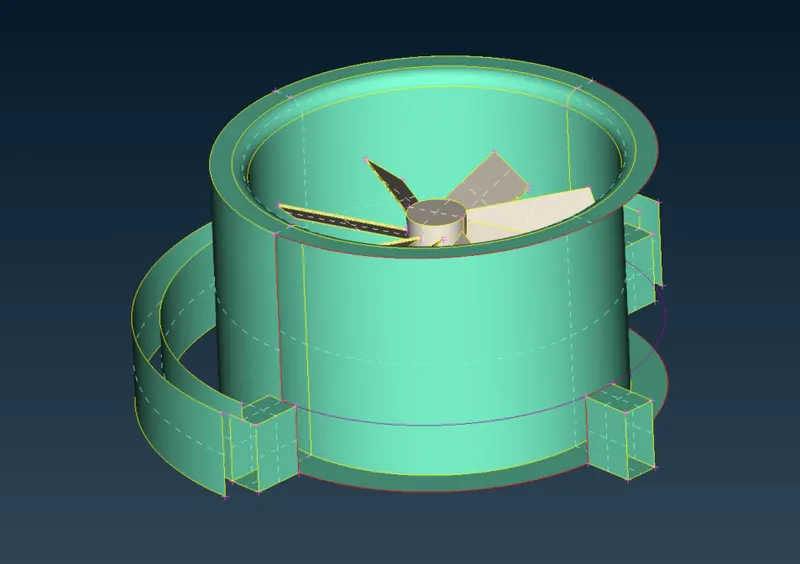
We made the curve(left curve also)
This option is best as this option is just copying the curvature as required.
Let's make a new surface.
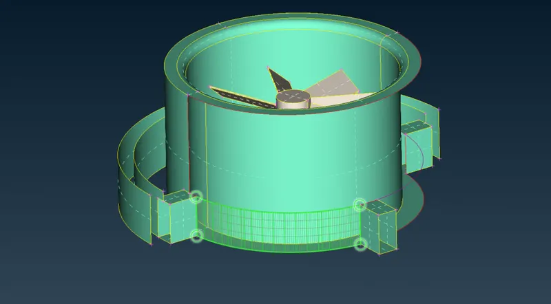
Next surface
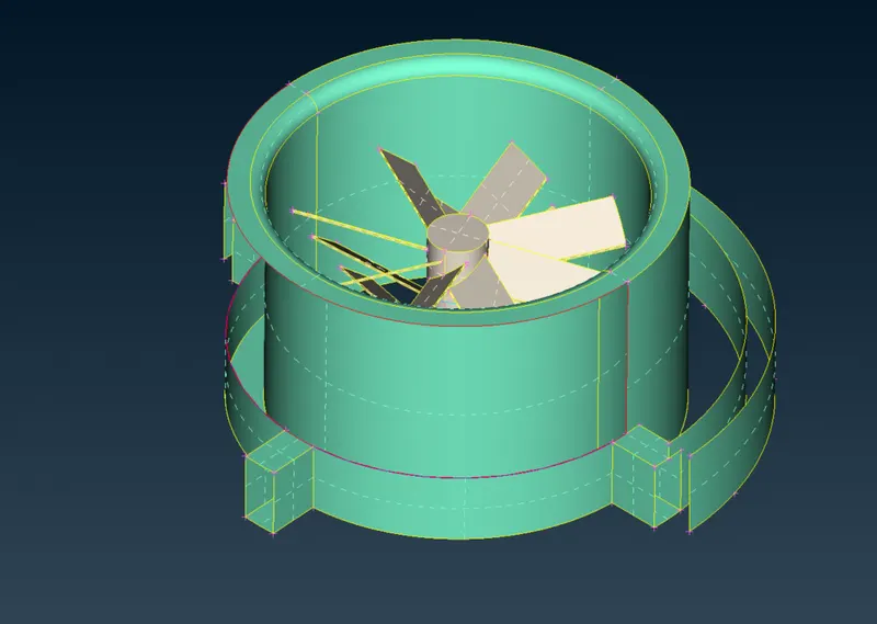
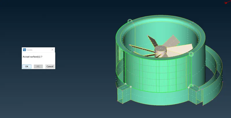
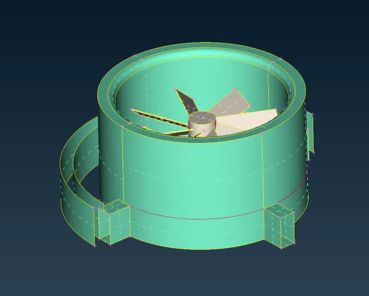
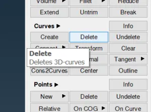
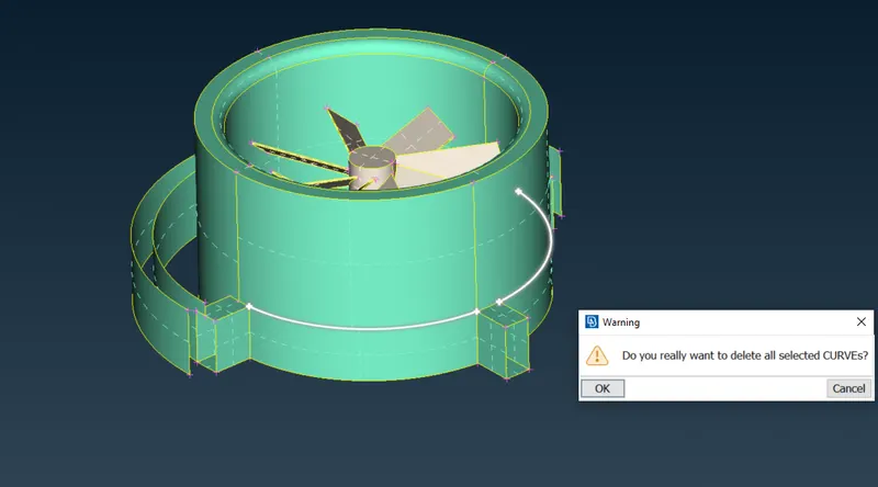
After this, we can go ahead and delete these curves.
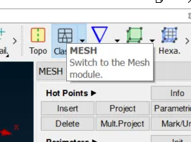
Then we changed the Perimeter length and change the resolution.
The mesh which is required in the body also needs to be taken care of while choosing the perimeter length.
Post this we did TOPO and we find this,
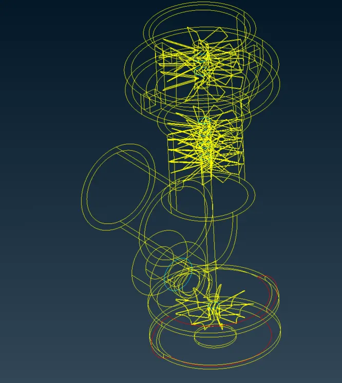
We have one more red co, we will use the Transform tool
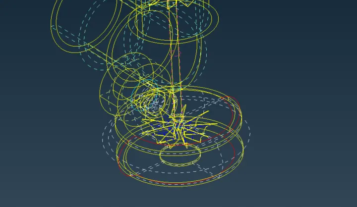
We will be making new Hot points and then moving ahead, the reason for making hot points will be clear by the method.
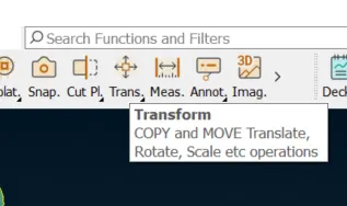
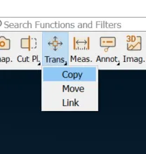
Use the Copy tool.
Before using we did
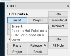
Insert a new Hot point
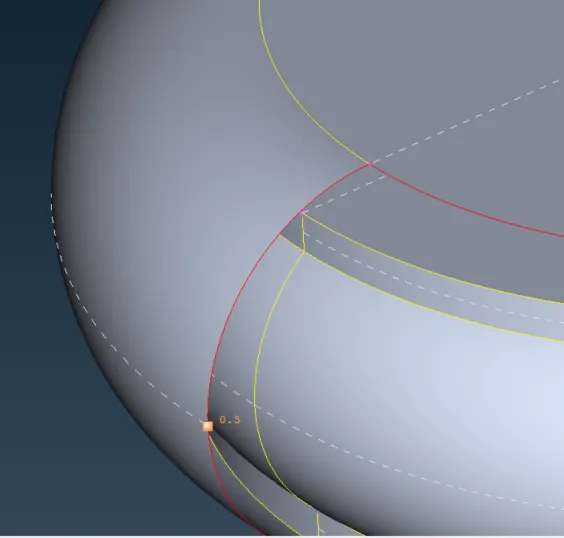
After selecting copy in the Transform tool,
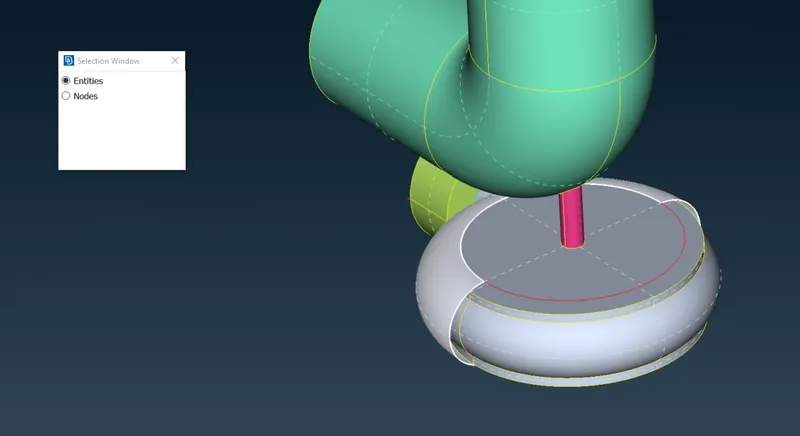
Select the entity we need to copy
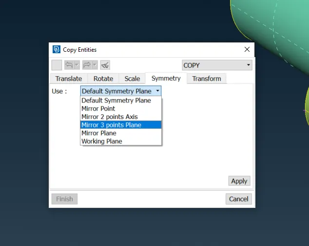
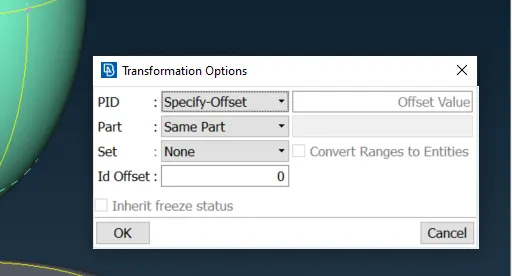
Click Ok after selecting the three points about which we need the plane to be made.
Click on the finish button.
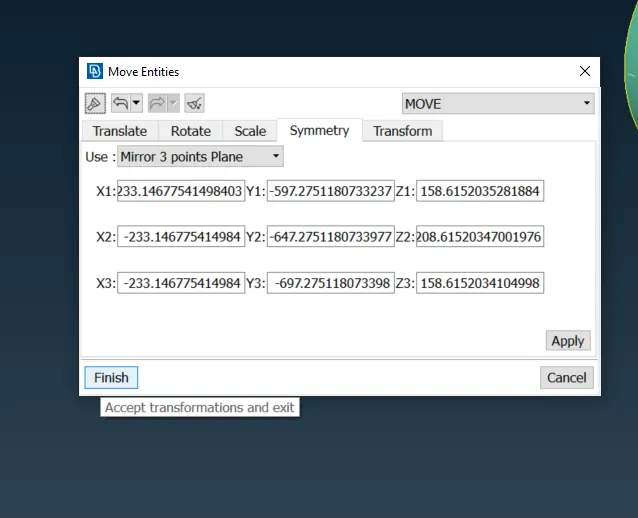
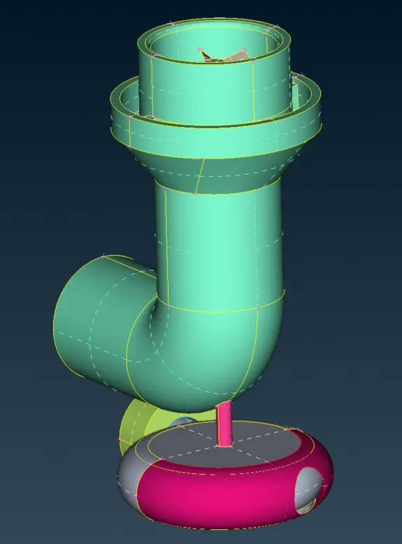
We made the entity look like this.
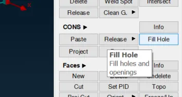
We will be now moving ahead with the fill hole option
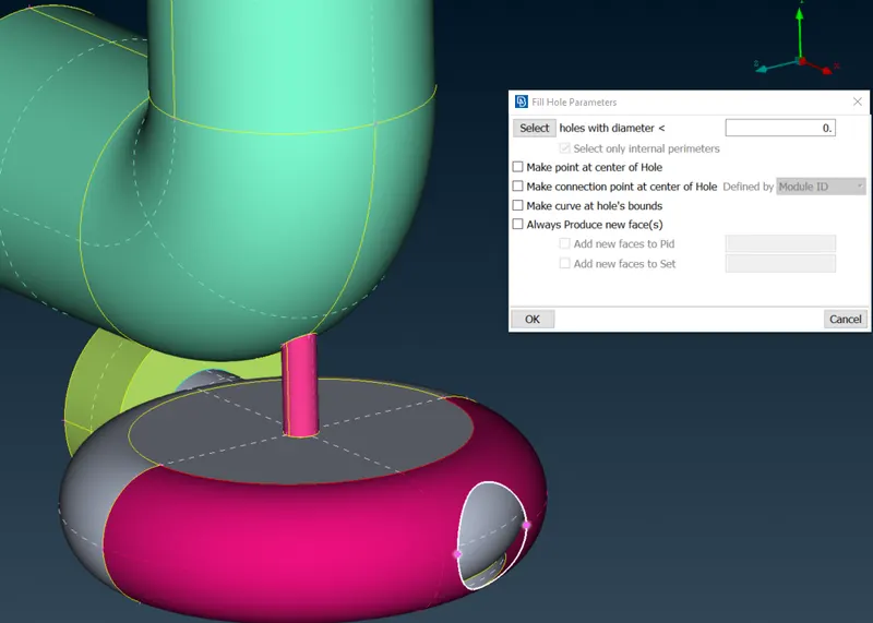
Now, to clear the red cons we need to perform one TOPO
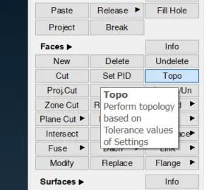
Post doing the TOPO, we have this:
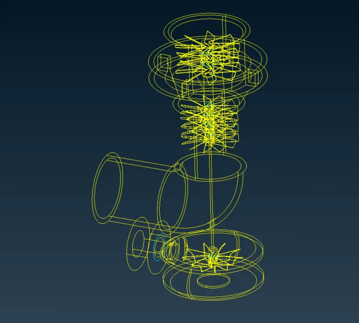
The triple con which we are finding in this view is important so we will not be removing this.
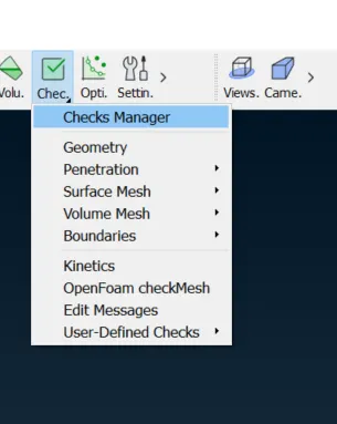
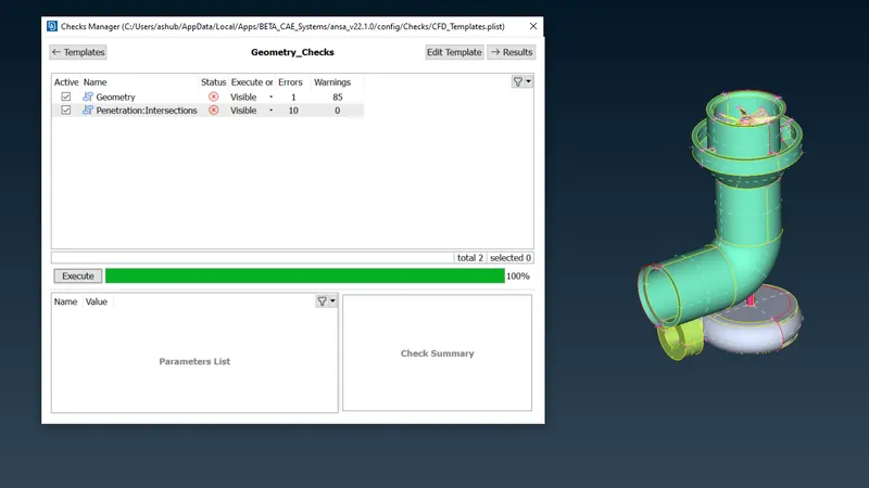
Let's run a Geometry check.
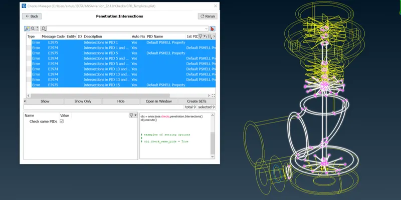
We see the favorite part of Intersection errors are coming which is generally near to the blades.
Let's start with blades.
Let's Hide the Body part
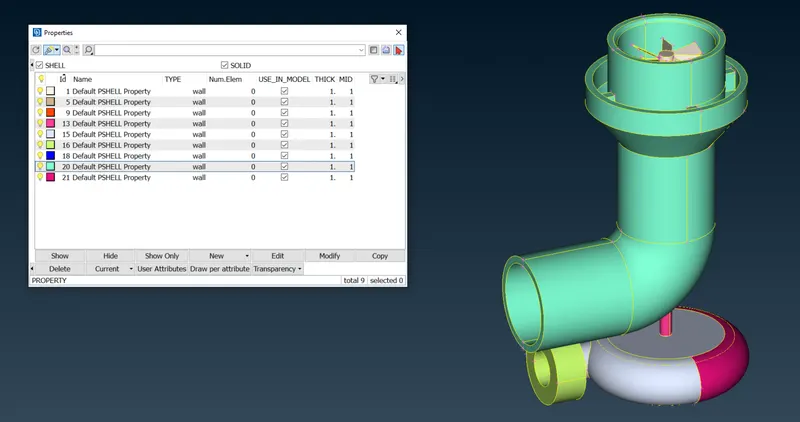
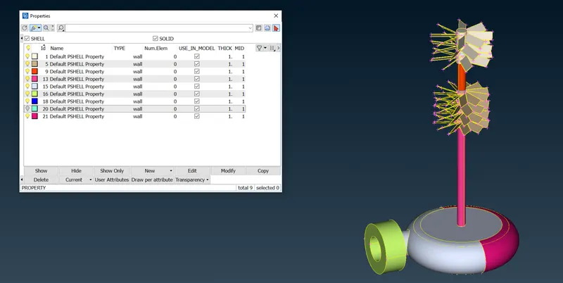
Let's remove what's not needed and then we can go ahead with the modification of intersection errors in the part of the blades.
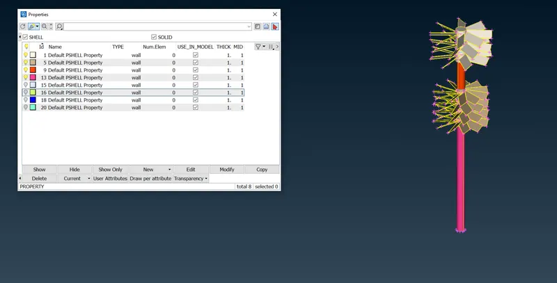
Start with TOPO
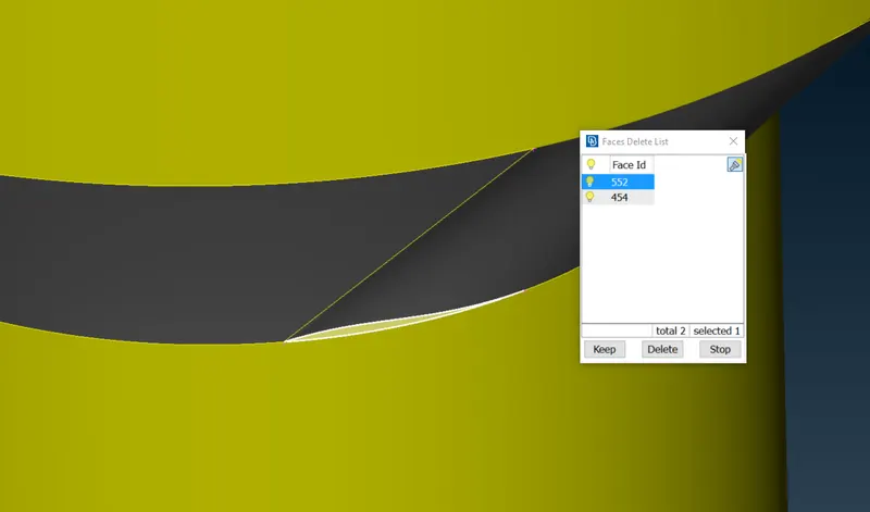
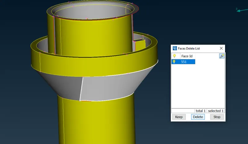
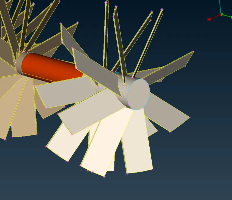
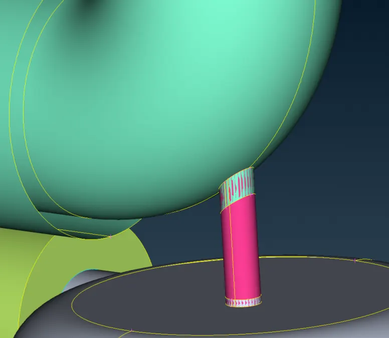
Since we can see one extra surface as the cover of the shaft section, we will be using the delete faces tool for going ahead for clearing the Triple cons
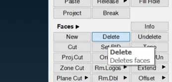
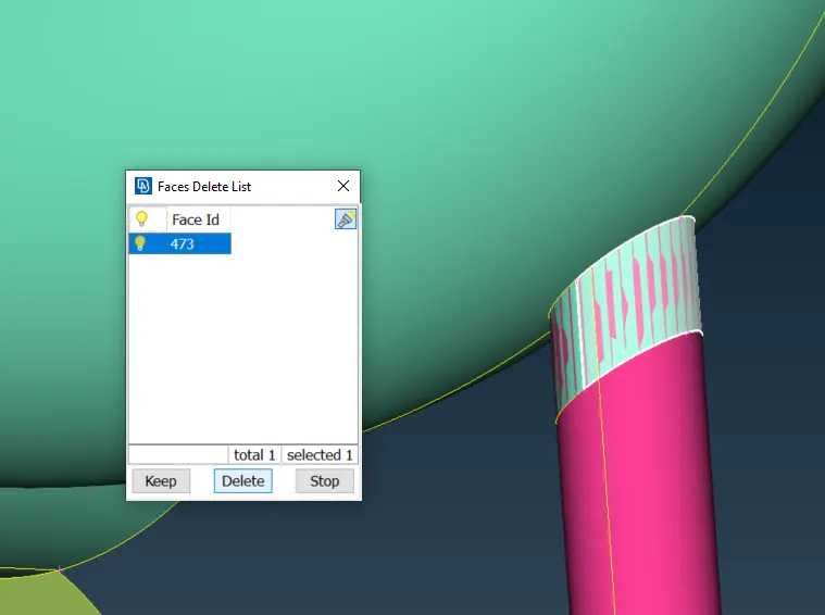
Use the Delete Faces tool.
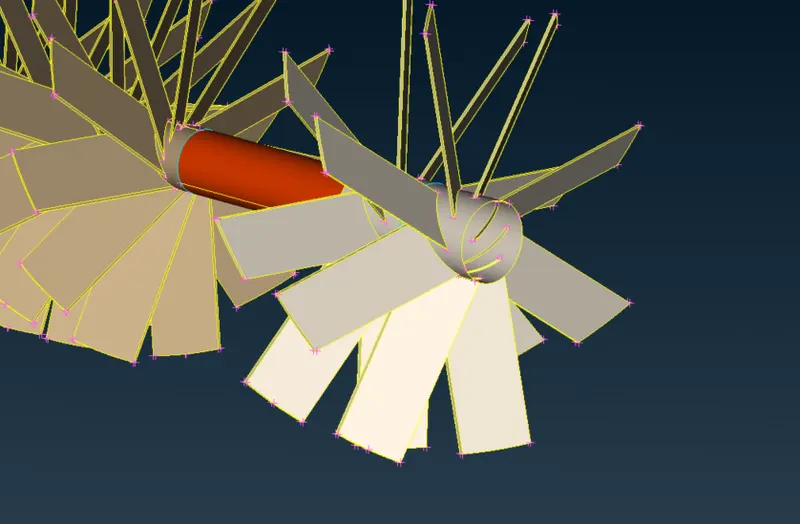
The Triple con is now removed and then we can move ahead for another triple con.
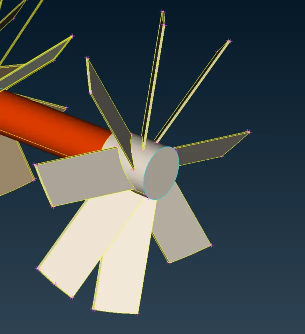
Again use the Delete face tool for getting rid of this
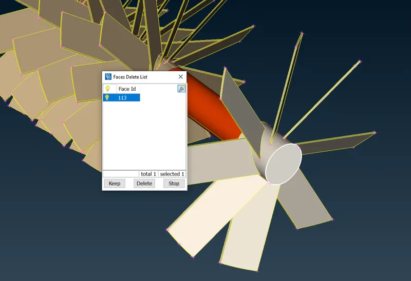
Post clearing that we can see:
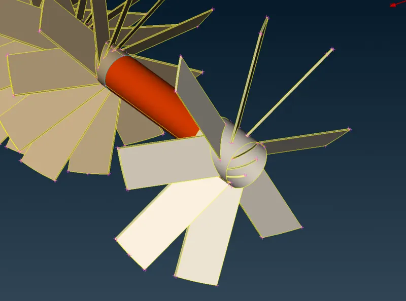
The next error is this:
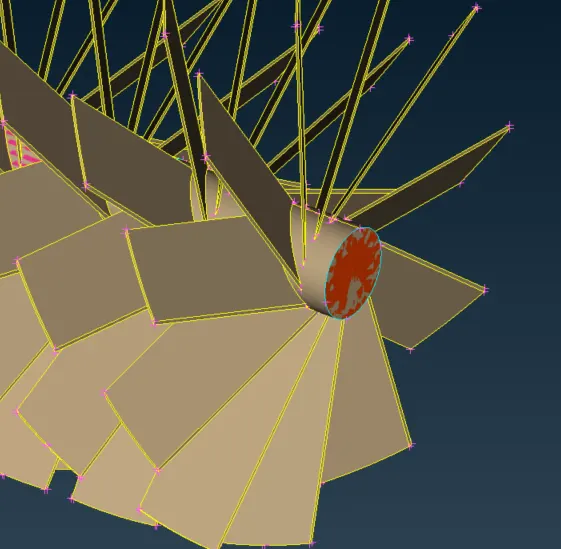
Follow this method for solving the triple con in the shaft
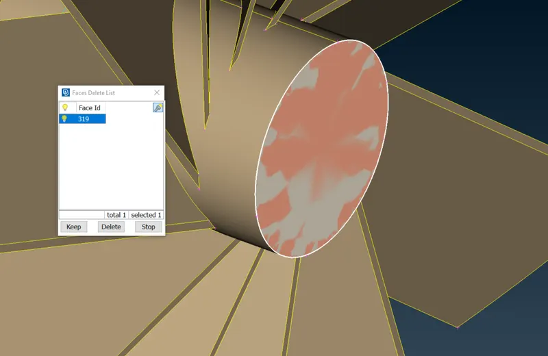
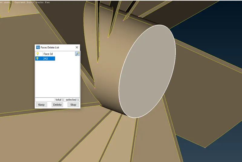
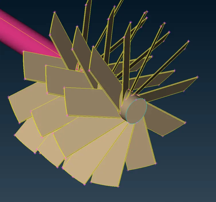
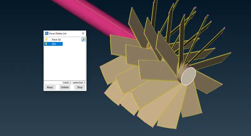
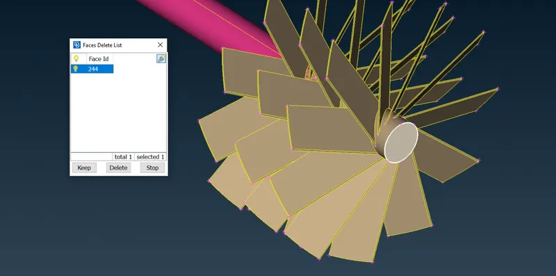
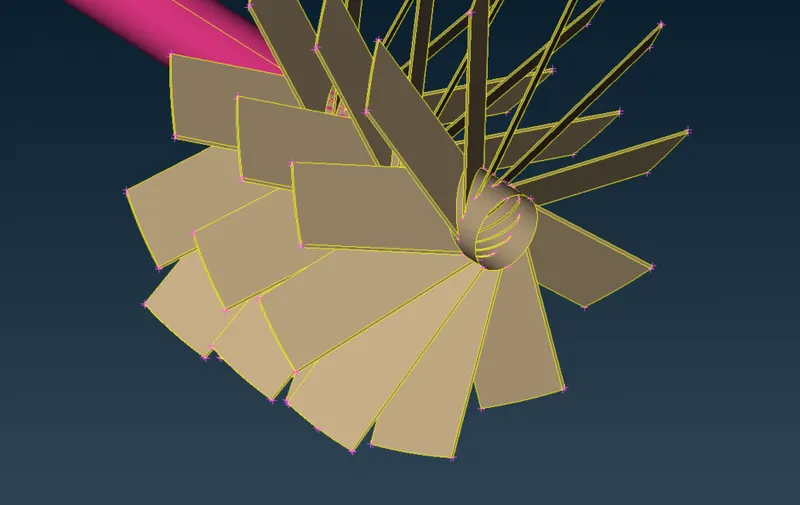
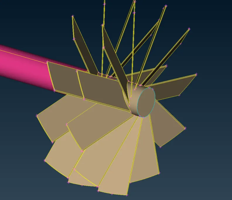
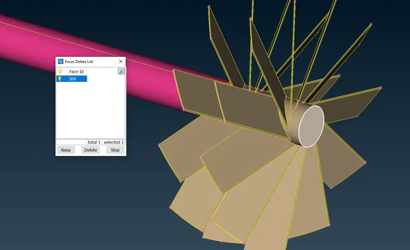
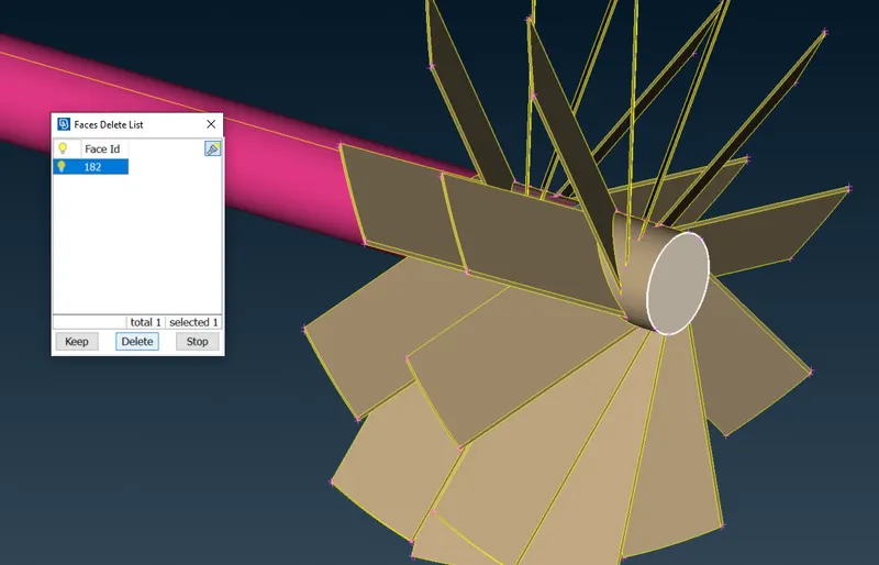
This triple con is removed and then we will leave the left triple con on the shaft as there we can see overlapping surfaces.
Now remove the Lock button and then move ahead with making a difference in the face.
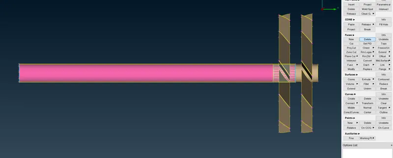
As we can see currently single face is being selected on selecting the shaft.
Let's project to isolate the surfaces.
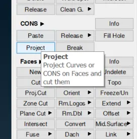
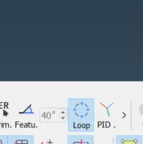
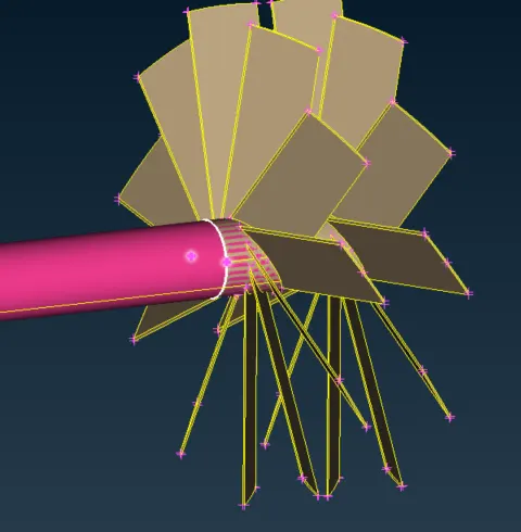
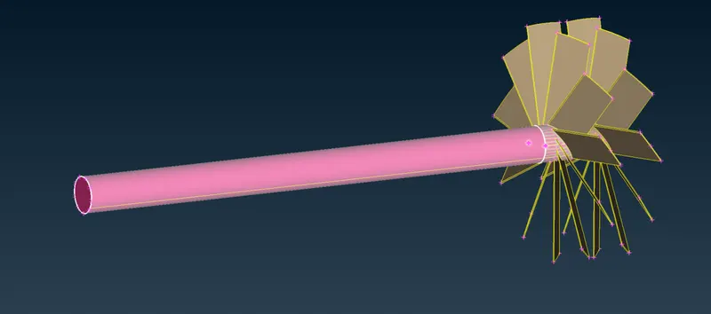
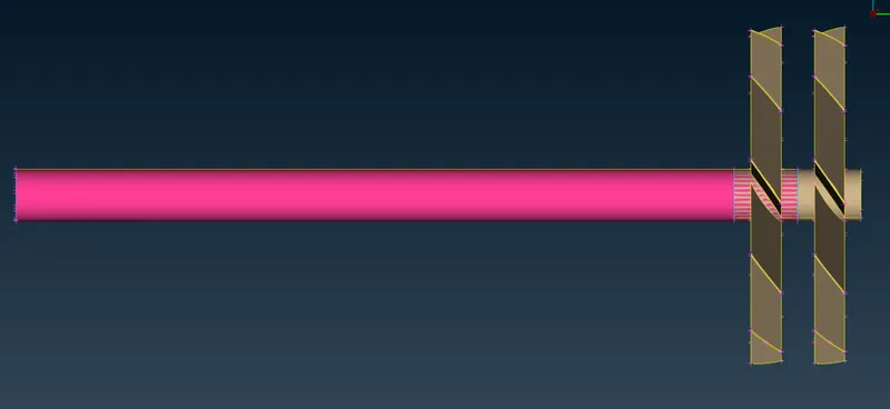
Now we can see two triple con so the surface can now be differentiated.
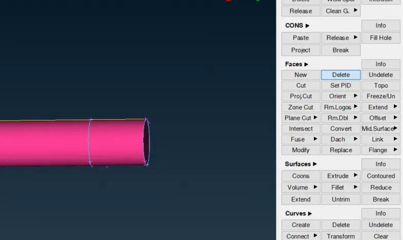
Post deleting we see the overlapped surface is now gone.
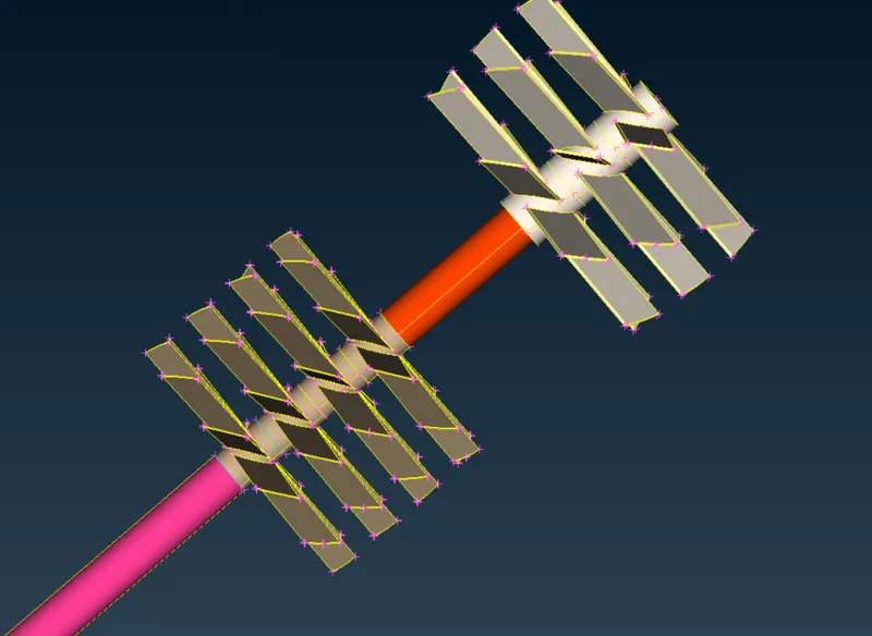
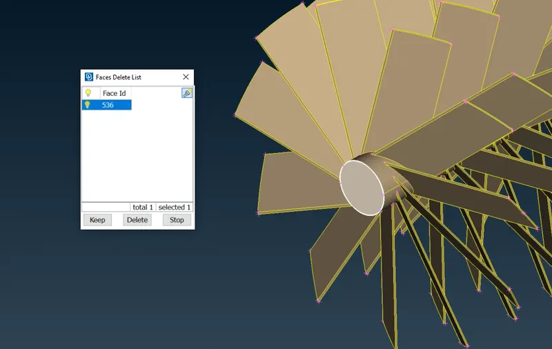
We will remove the last triple con now:
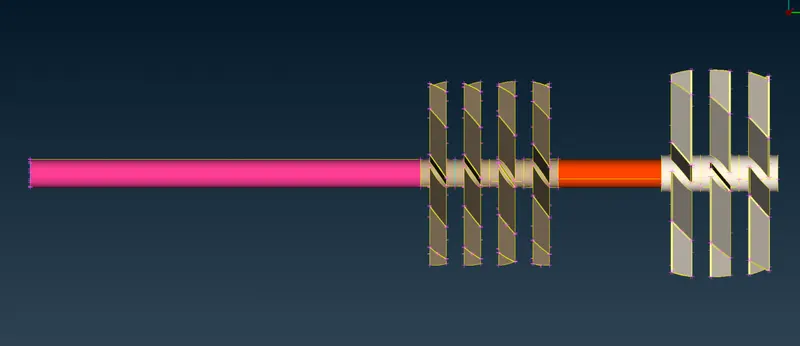
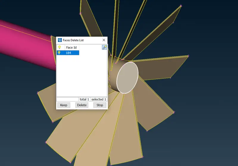
Deleted the face now we will move ahead for the geometry check.
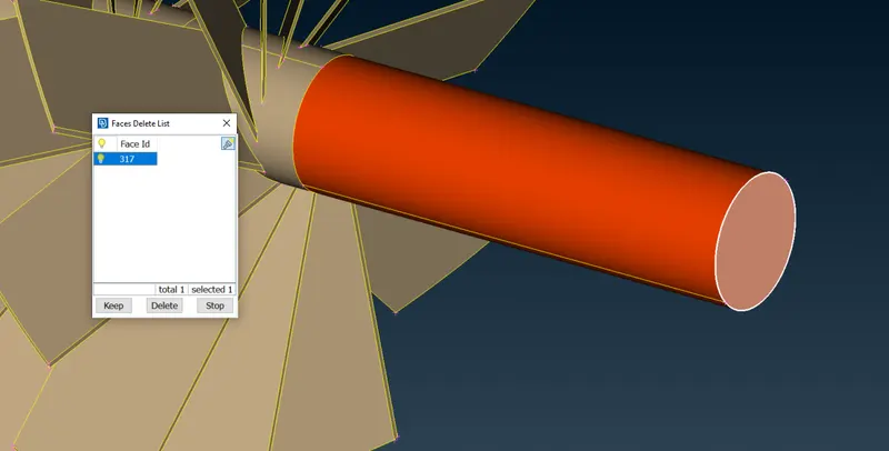
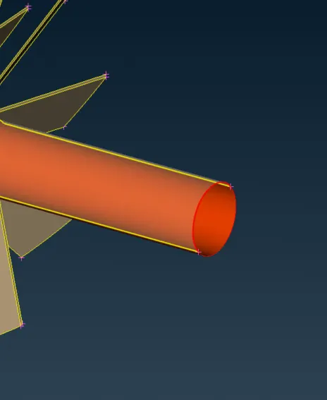
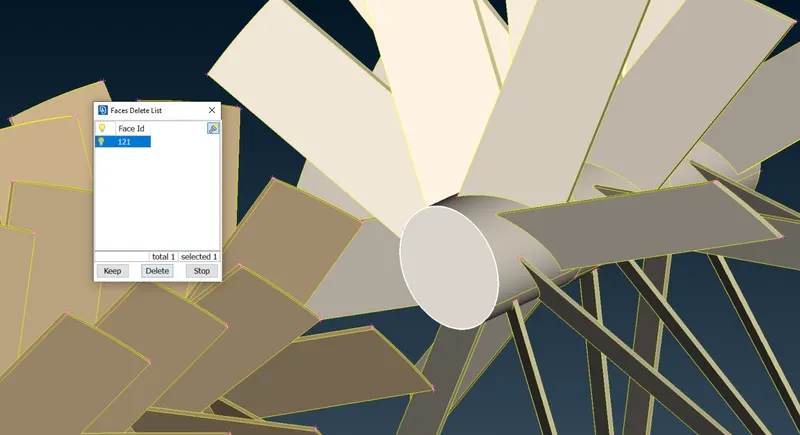
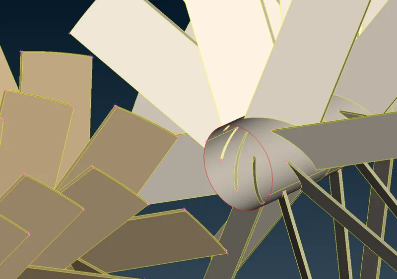
Add a new face in the red con area to get rid of the red con:
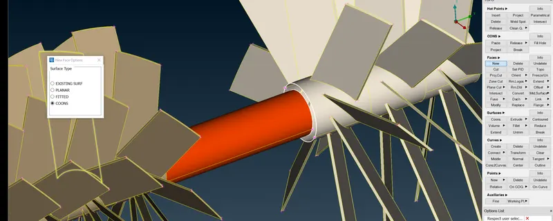
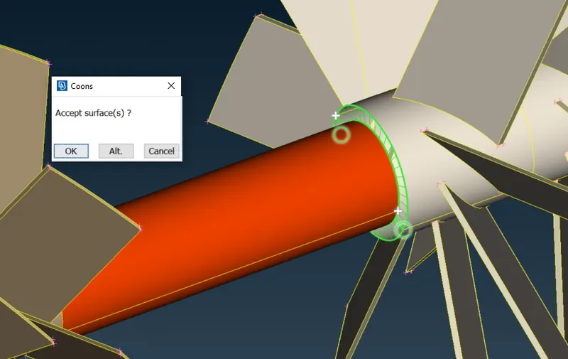
The model asks to assign the surface an type of PID
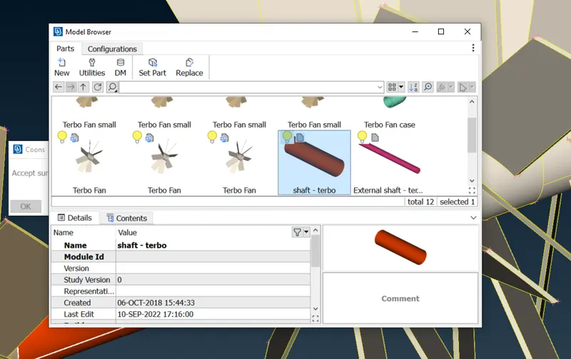
So now the intersection errors of this shaft part are now gone.
Hiding the entity by using the NOT too, we can see
We are able to see the overlapping surfaces.
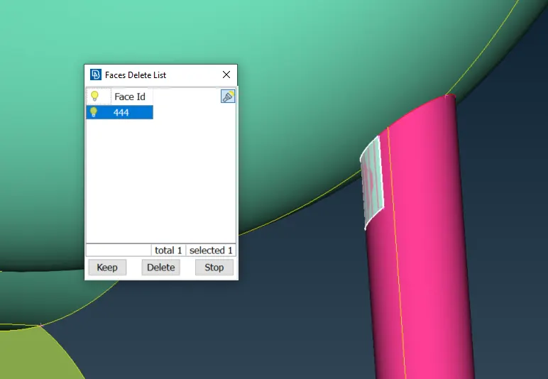
Checking we see we have developed 2 new red cons
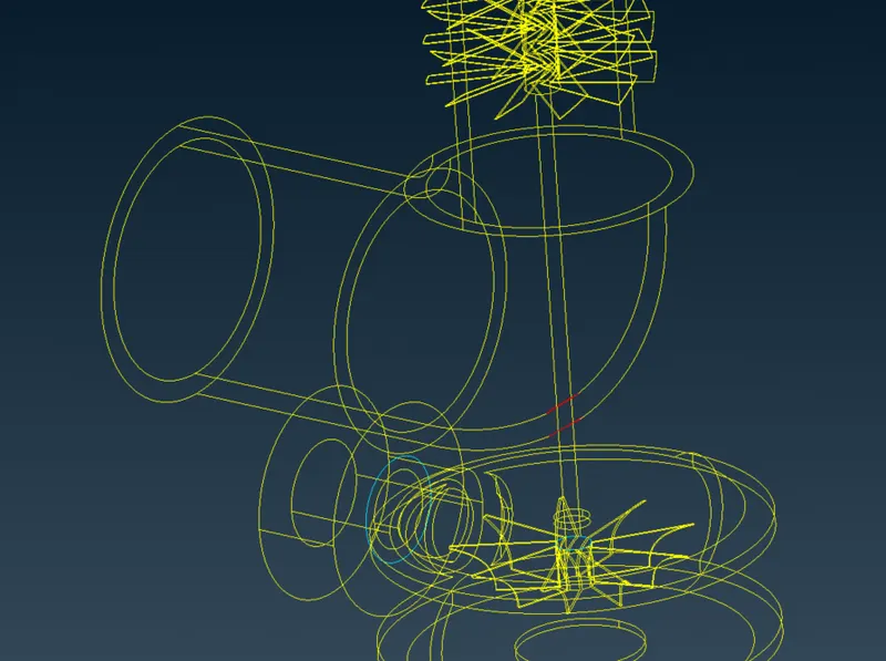
When trying to select the shaft part we can see the complete shaft is getting selected so,
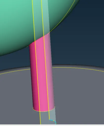
We need to project edges and make the surfaces isolated from each other to delete the part of the shaft which is not required.
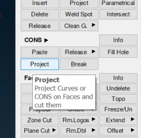
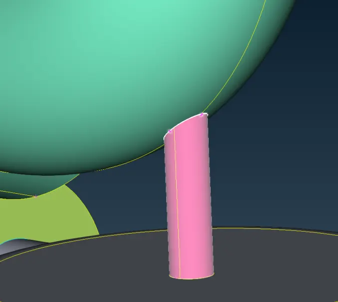
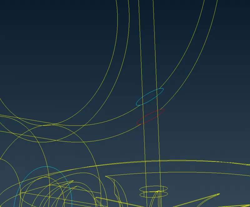
Let's make one more projection of curves
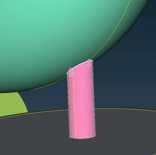
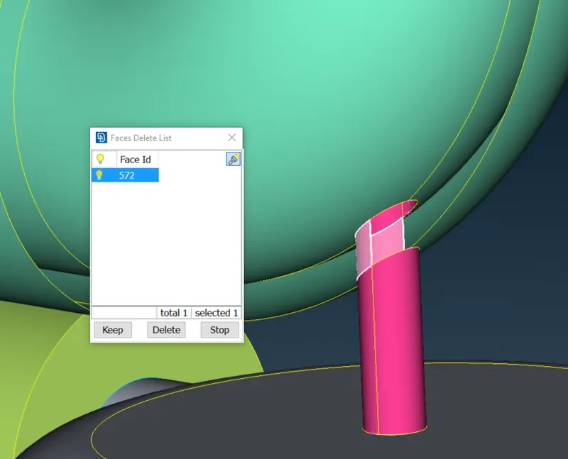
Post deleting the shaft part where we were finding Intersection error
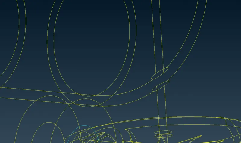
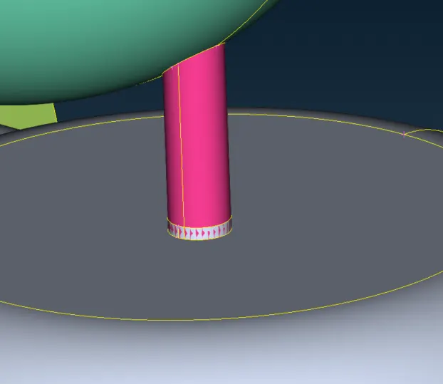
After using the project method we can do the same process as above
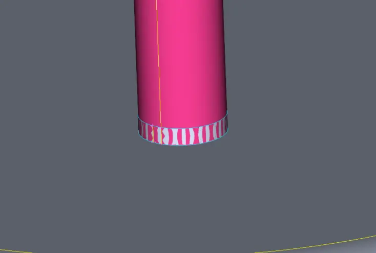
After deleting the surface we can now get a look at the errors and do a geometry check again
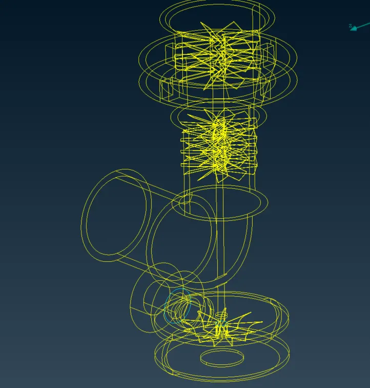
Only 2 Intersection errors left so we will be looking into them and clearing that part.
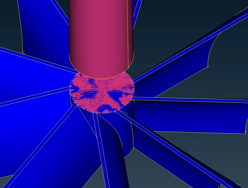
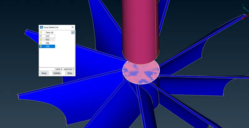
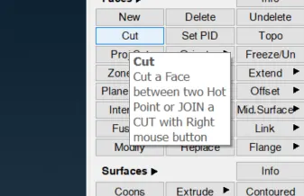
We will use the CUT tool to differentiate between two surfaces.

After using the CUT tool we have to select the points where we need to make the cut and then the surface looks like this
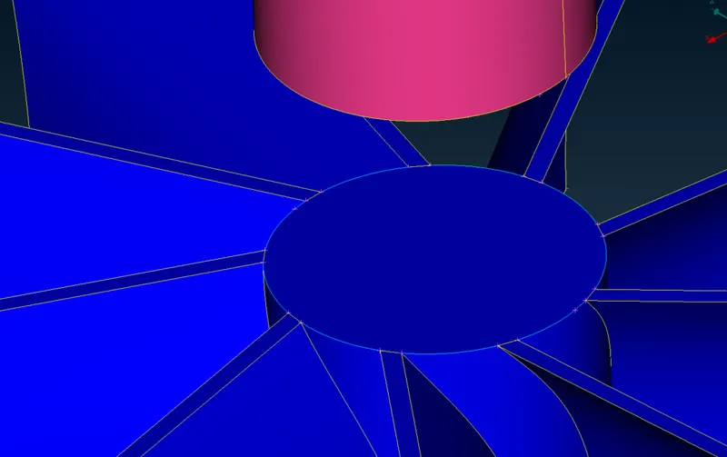
After making we can see still the blue con is there so we will be deleting the face.
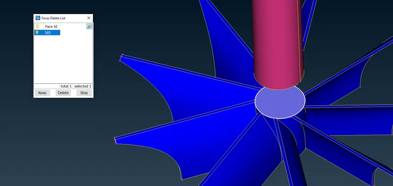
Post deleting this face we can see developed new red cons so do TOPO and they will be gone.
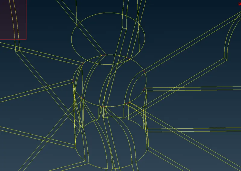
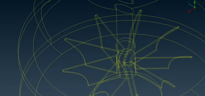
Here is the cleared section now
One more intersection error here:
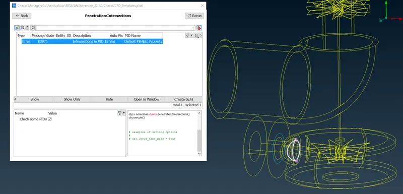
Since there is no use for the highlighted part, we will delete the part and then we can re-run the Geometry check
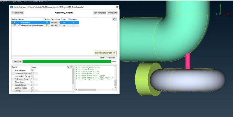
No intersection errors.
Let's go for surface meshing now.
Watertight mesh: Perfect mesh with no leakage, which means we don't need any holes
So we will be making surfaces for all holes that are coming for making the geometry ready for surface meshing.
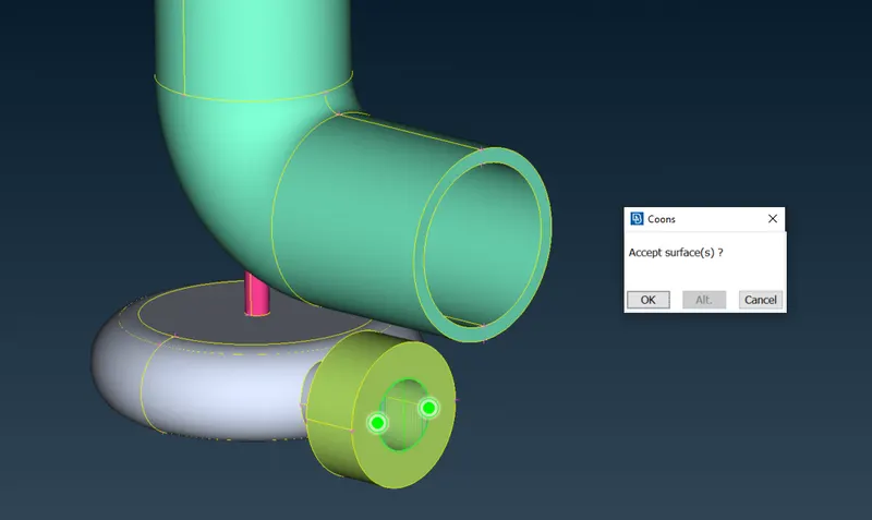
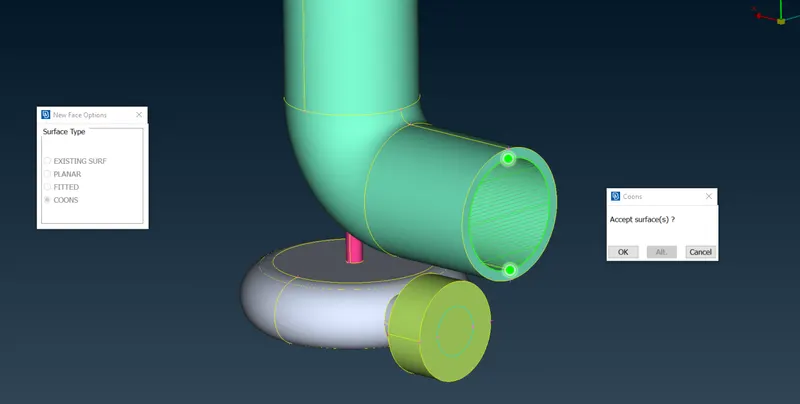
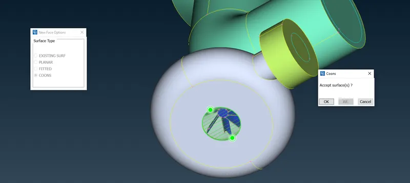
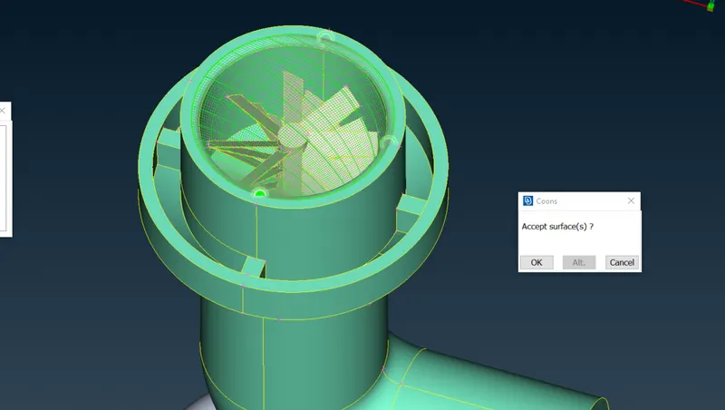
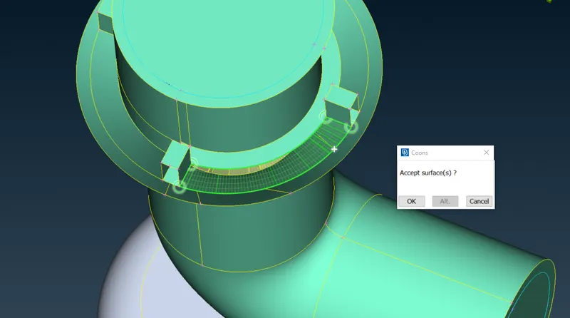
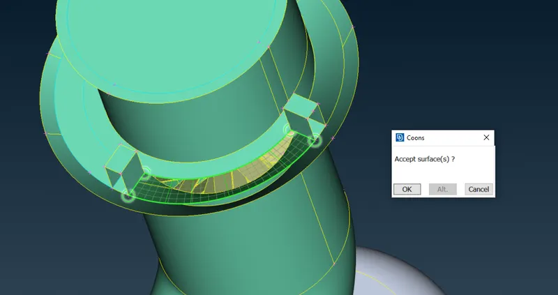
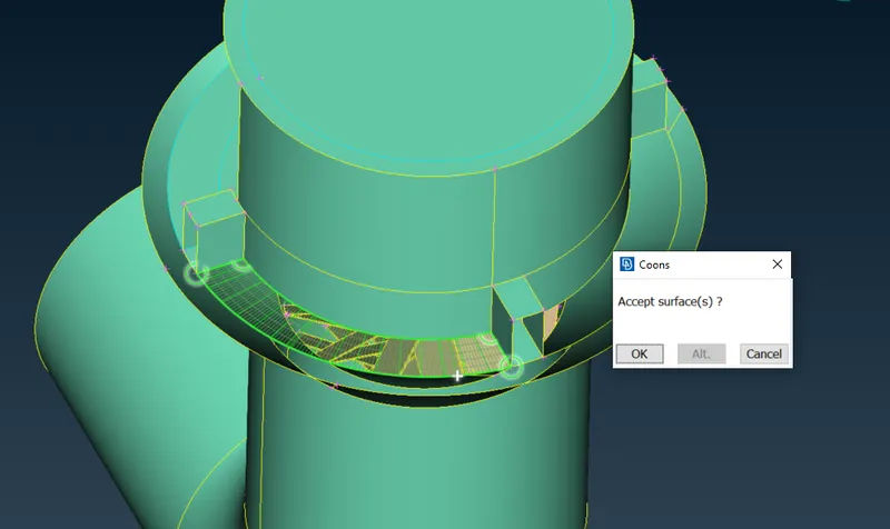
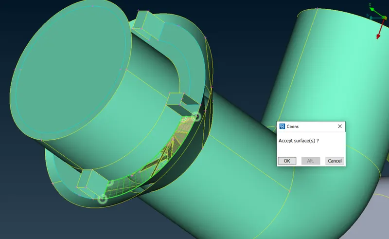
Making a loop was not useful so let's, take the selection again in entity mode and do the covering of holes
Let's assign PIDs
Post assigning PID we did the surface filled by Planar option and we are not getting errors again we did assign PIDs
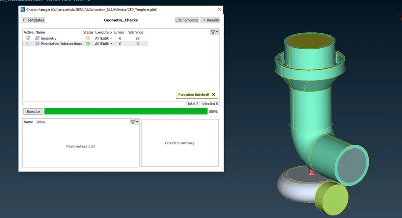
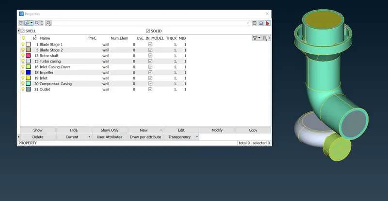
We can see PIDs also in the above screenshot.
We learned different kinds of meshing in the next class.
Let's start with Meshing:
We have to take care of this:
- Blade stage-1 = 1 mm
- Blade stage-2 = 1 mm
- Impeller = 2 mm
- Shaft rotor = 1 mm
- Turbo casing = 5 mm
- Compressor casing = 5 mm
- Inlet casing cover = 5 mm
Let's start with only the visible Compressor casing.
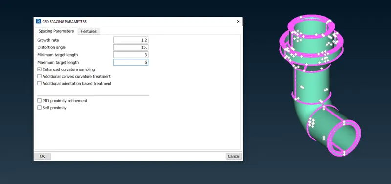
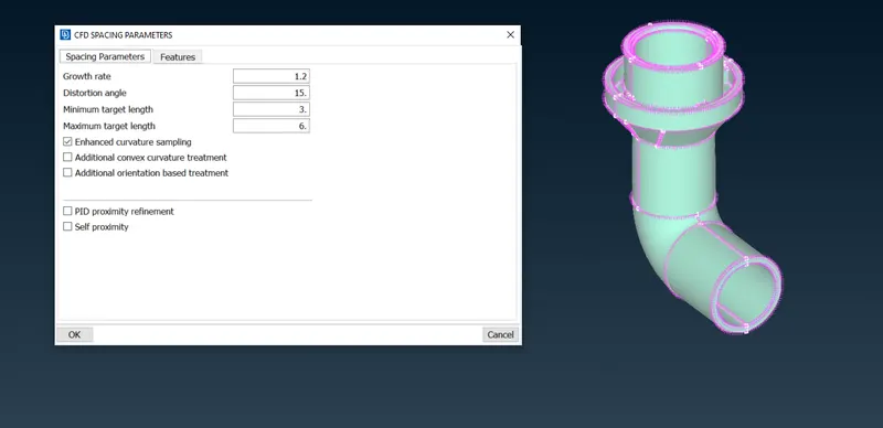
The Advances Front will give better results but we will be getting fewer elements and also not that much-structured mesh so we will be changing Spacing parameters as below:
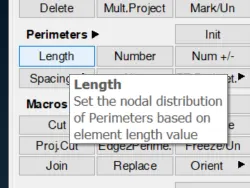
Instead of using this, we will be using the Spacing tool
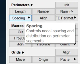
For macros also,
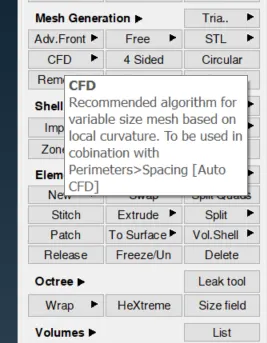
Go for CFD mesh now
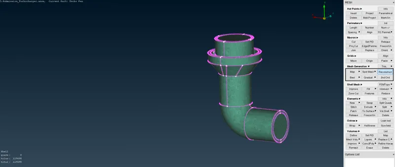
Using Spot mesh
If we imply quality criteria in mesh we will have to clear the mesh as per quality for getting accepted as we are not able to get proper meshing with normal conditions.
We will go to Turbo casing now
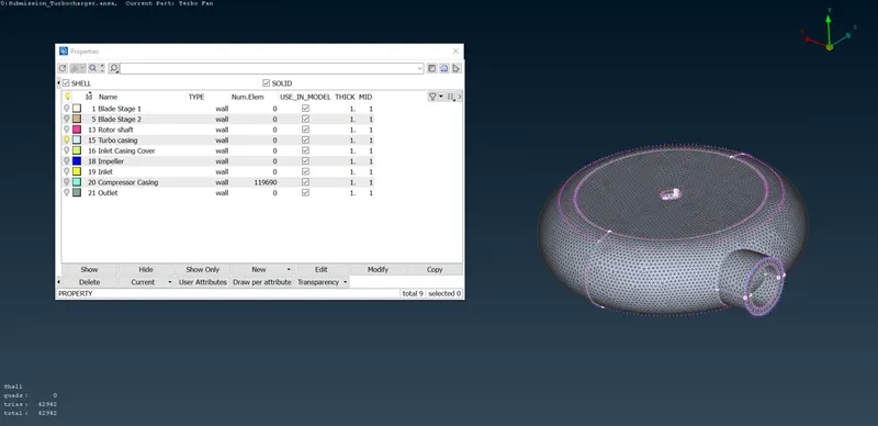
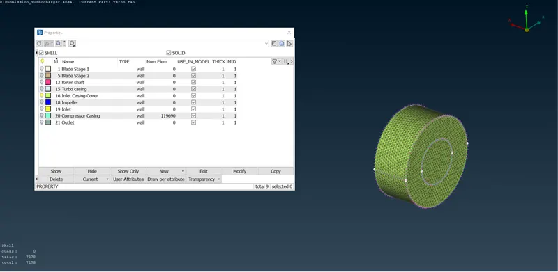
We can do combined also, let's do that,
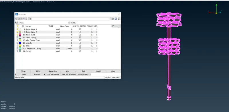
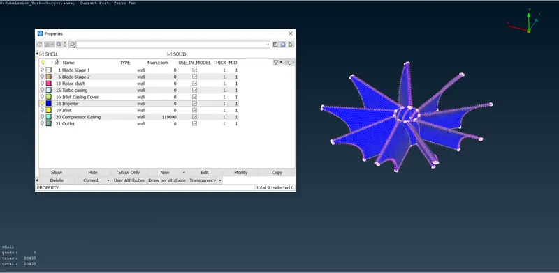
Some parts were left out from meshing so we will be completing them by the Show-only tool and meshing them again.
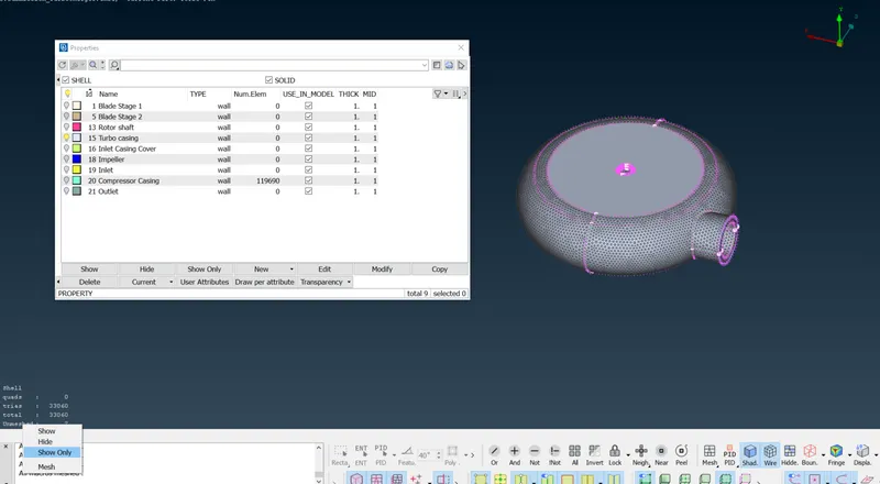
The meshing not done is the reason as we have different confusions going for different geometry parts,
We will use the Option Free tool for going to do the mesh of the left part
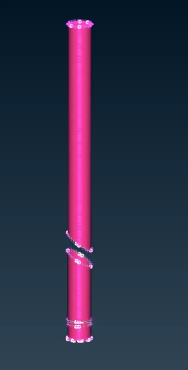
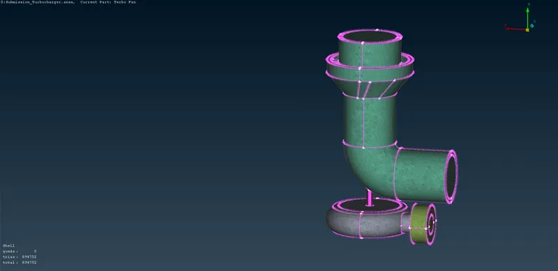
So we did the complete surface meshing of the geometry.
To check what's surface mesh is and what implication it did to our geometry we can use the CUT Plane tool for cutting the geometry.
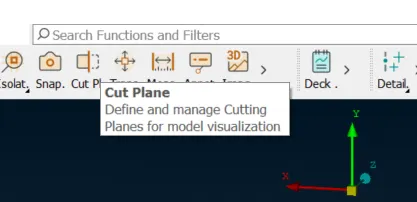
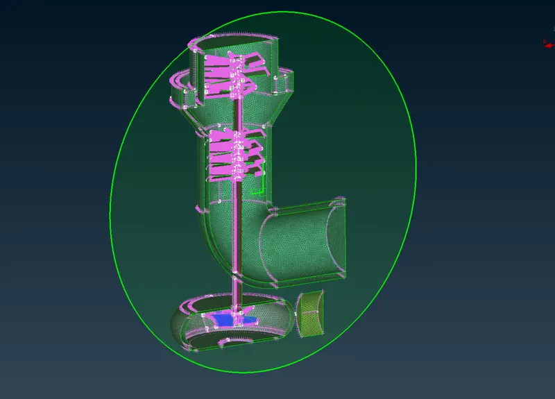
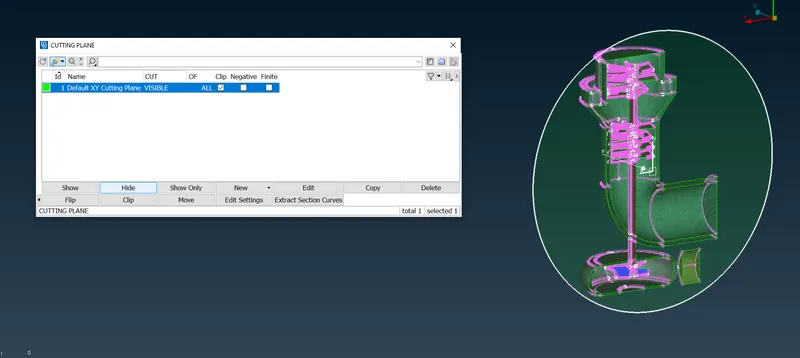
Hiding the cut section plane again so that we can use this.
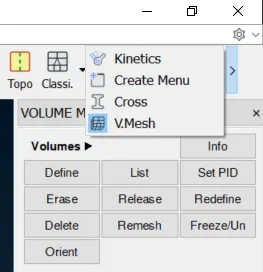
Go to the Volume mesh deck
Define the volume

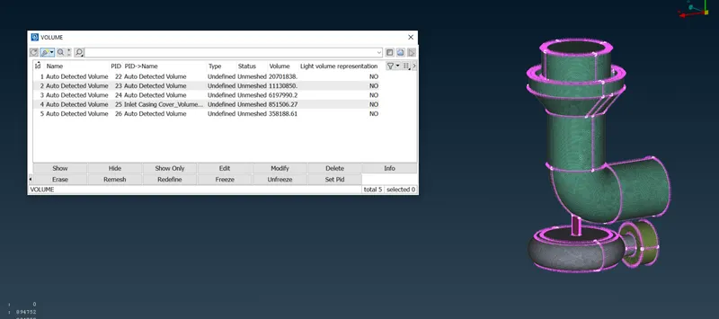
5 different volumes were detected automatically
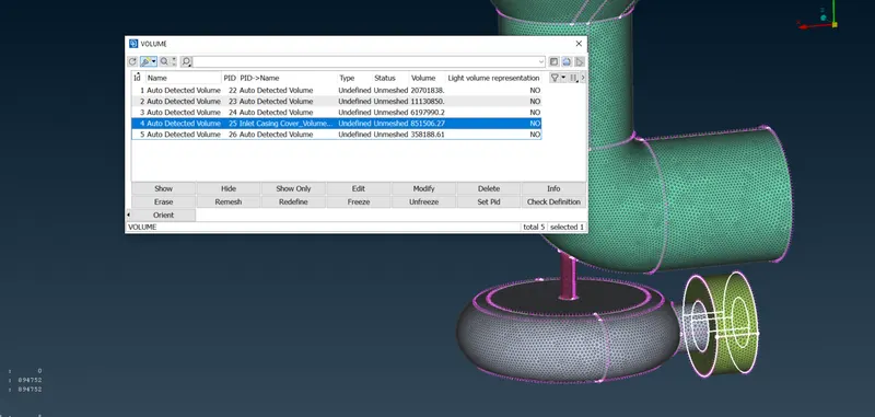
We delete the external volume since it will take time for doing the volumetric meshing.
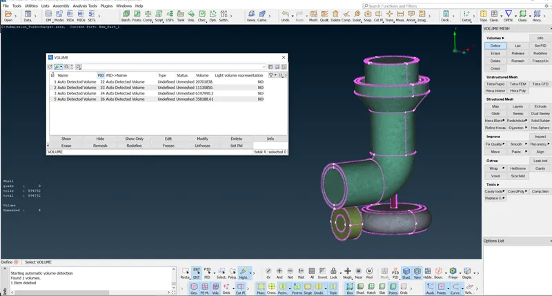
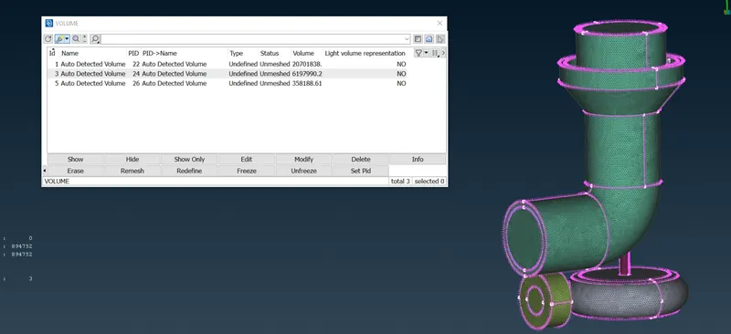

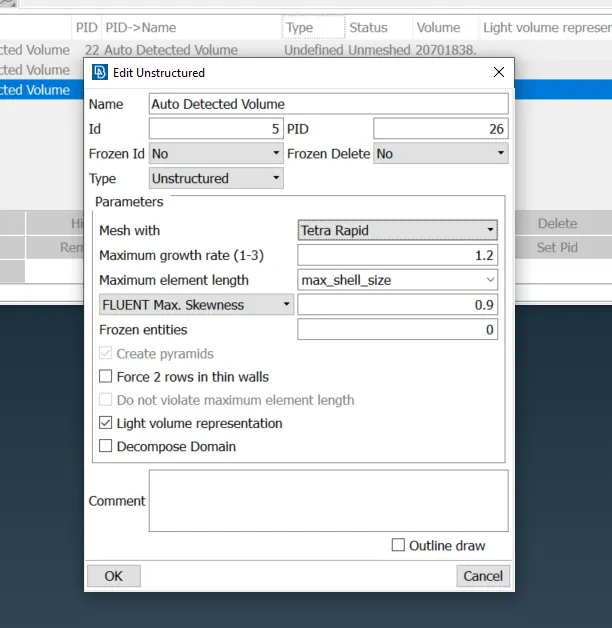
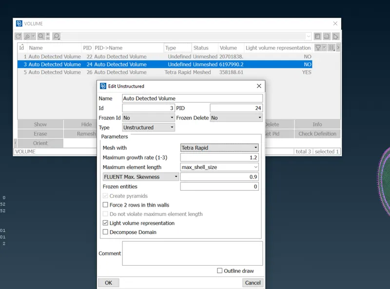
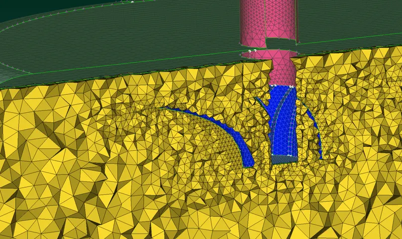
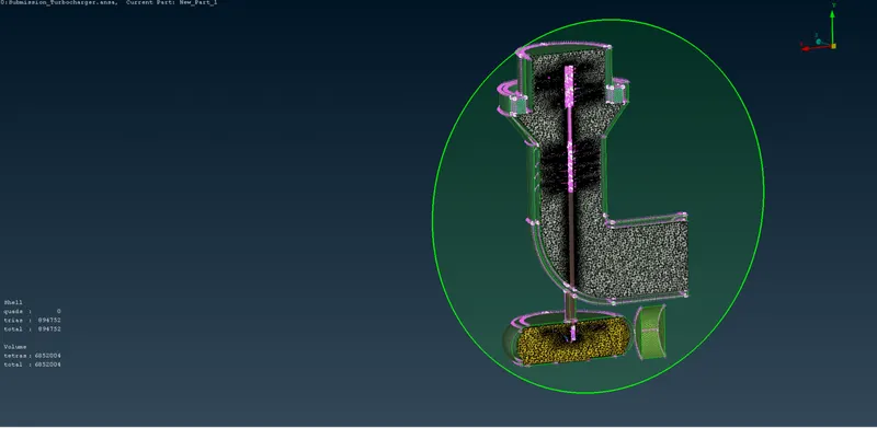
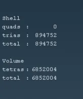
We did the complete meshing now with both surface and volume mesh done.
Result:
The file after meshing has been attached to the report via a google drive link. We completed the meshing of the Turbocharger as per requirement.
Link:
Please click on this Google drive link
Conclusion: We learned the basics of ANSA software and also did our assignment for Week 3 for the Surface and volume meshing of the Turbocharger.
Thank you.