Week 2 Challenge : Surface meshing on a Pressure valve
Aim/Objective: To get the complete week 2 challenge done and get multiple learnings included in this geometry.
Procedure: Followed the complete lesson which was recorded for the Live lesson which was taught for the Week 2 challenge and basics also.
Learning Outcomes:
1. Opening the file and doing the basic adjustments:
We will be going ahead with Week 2 challenge now.
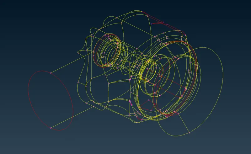
Shadow mode:
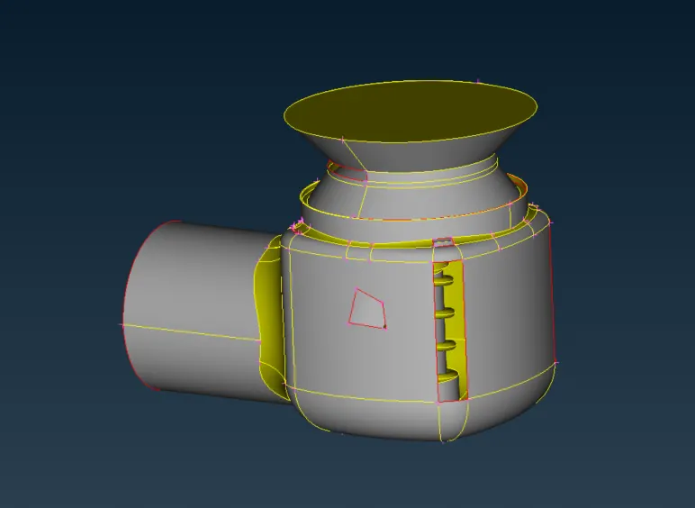
We can switch to shadow mode by using 'Ctrl' + 'Shift'.
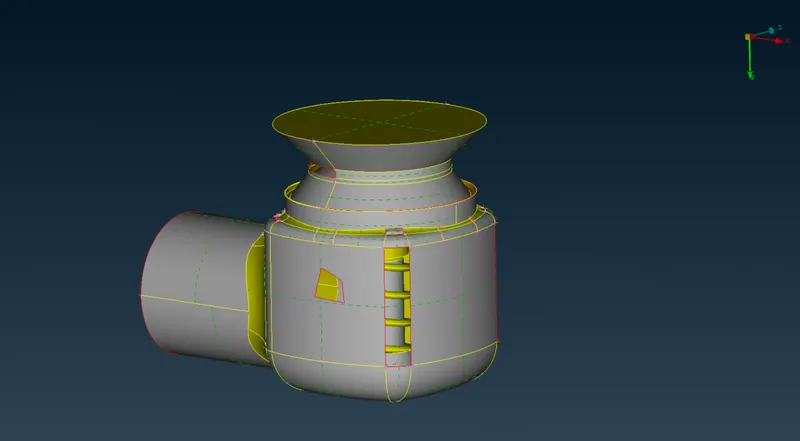
We can see that we are having a no. of Red Cons and multiple errors.
We need to fix these by doing Geometry Cleanup.
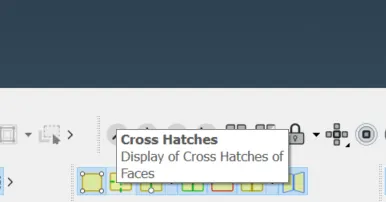
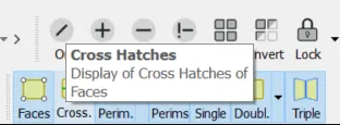
Firstly let's enable the Cross Hatches option.
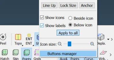
We have forgotten to switch on the labels let's make them visible or it may be difficult for us to navigate.
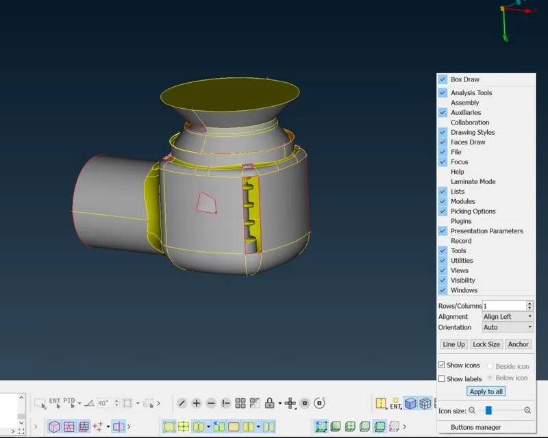
Post clicking that we will be able to see the names of functions.
Now, let's do enable the Cross Hatches option.
Post enabling we will be seeing the geometry in this form in shadow mode.
2. Basic cleaning using inbuilt tools:
Whenever we open one geometry. Always perform TOPO from the 'Faces' section.
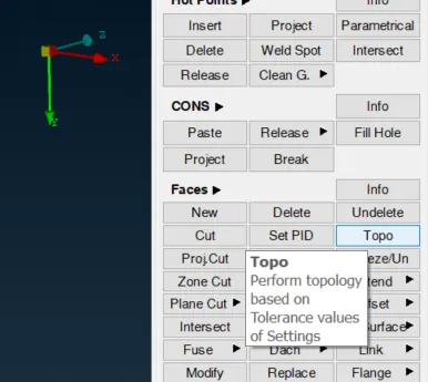
What Topo does is, if there is any error that can be automatically fixed, it will cure them by itself.
Do select the geometry by the 'Box Click' method and then do a TOPO.
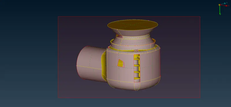
3. Manual correction of errors:
If there are major errors we need to do the clean-up by manual method.
Since in this file also we are not seeing any significant changes in the geometry. We will be checking the complete geometry by manual method.
Some CONS are very intricate in finding and they are very small that even in Wire mesh mode, we are not able to see any of them like:
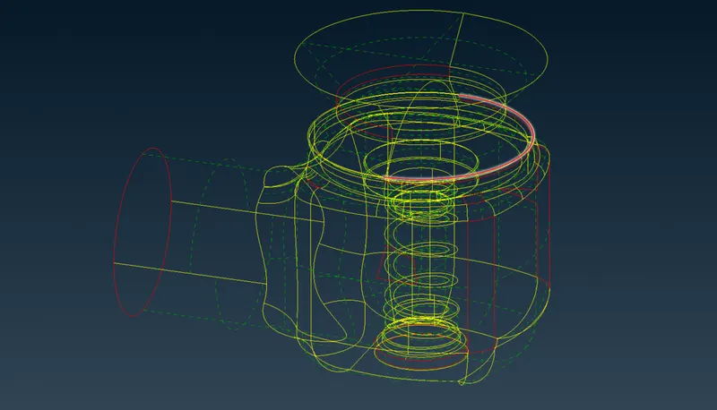
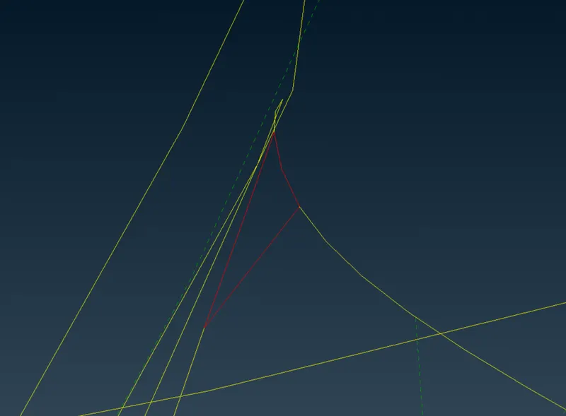
So these CONS can be found by doing the 'Geometry Check' method.
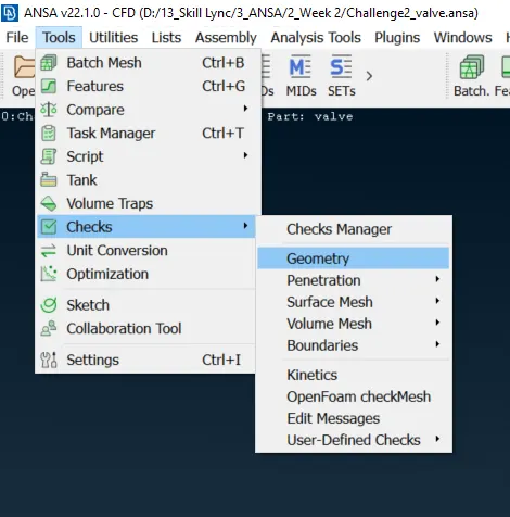
In this Geometry check method, we will be able to find out every type of CONS and error.
Let's first fix the errors which are visible first by normal methods then we will be heading for intricacies in geometry.
Understanding the New Faces Option first:
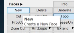
on clicking this window appears:
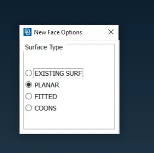
if we go to the explanation first:
COONS: According to geometry it will get a new face as per available CONS.
PLANAR: This just creates a plane independent of available space and domain where it needs to be created, not caring about the geometry also, the created surface will just be a plane.
FITTED: This just creates a planar but in a limited space.
EXISTING SURFACE: If there is any surface where there is an existing surface, then we will be going ahead with this method for creating new space.
Let's go with COONS first:
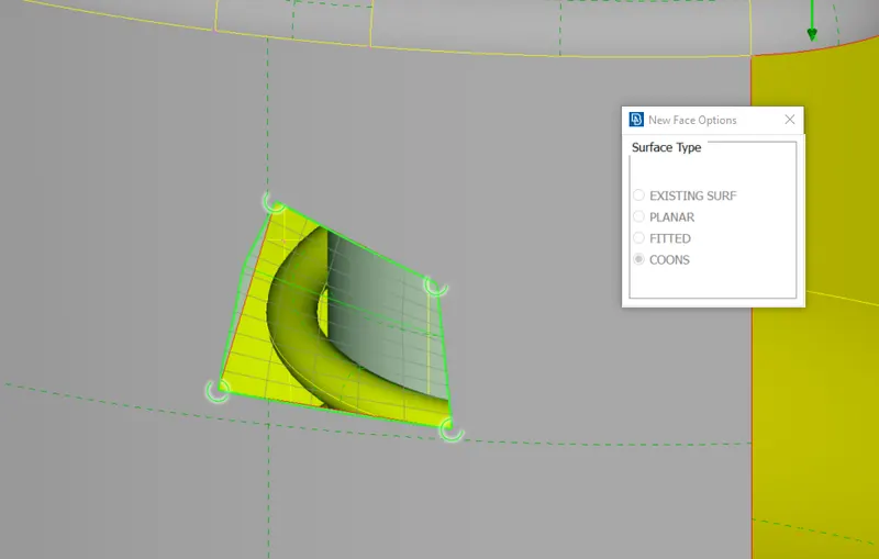
If we look at it in wireframe mode:
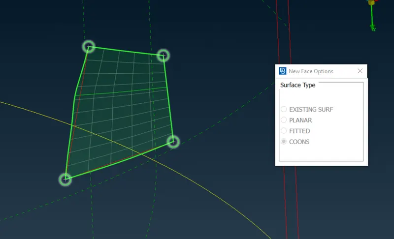
This is not what will help my purpose, actually overlapping but if we say Okay to this window, it will be created a new surface and the overlap won't be visible.
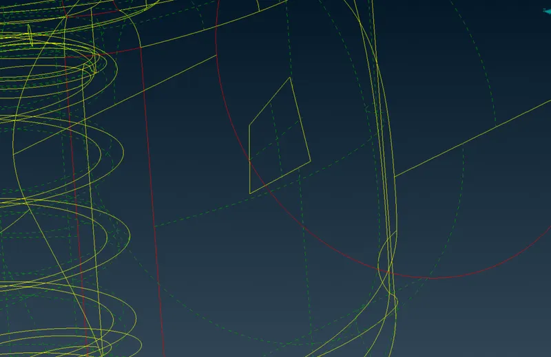
But as seen from Cross Hatches, we have created a new surface, so we also have a different method for filling holes.
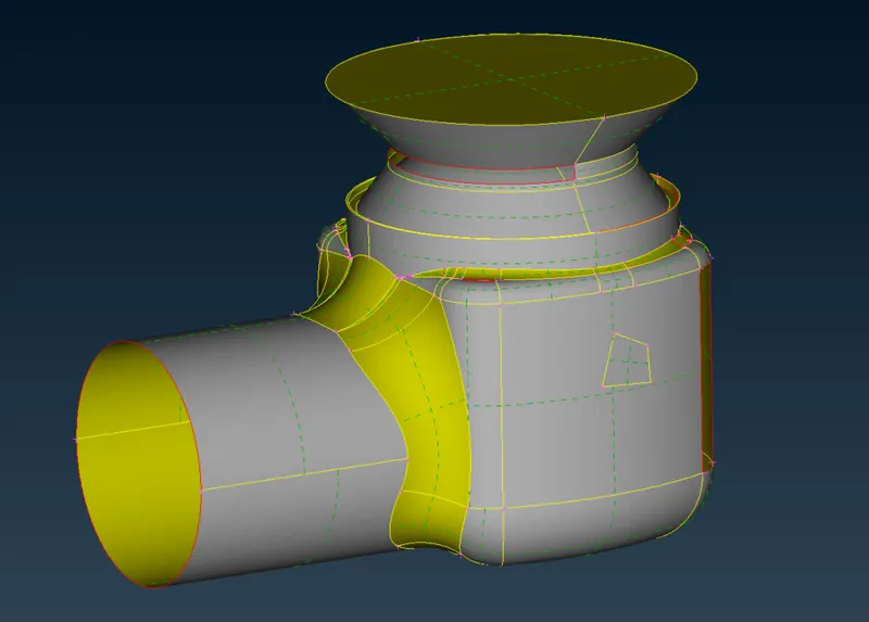
Instead of this method, we will be using this:
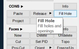
and then selecting the hole for filling and let's see the MAGIC:
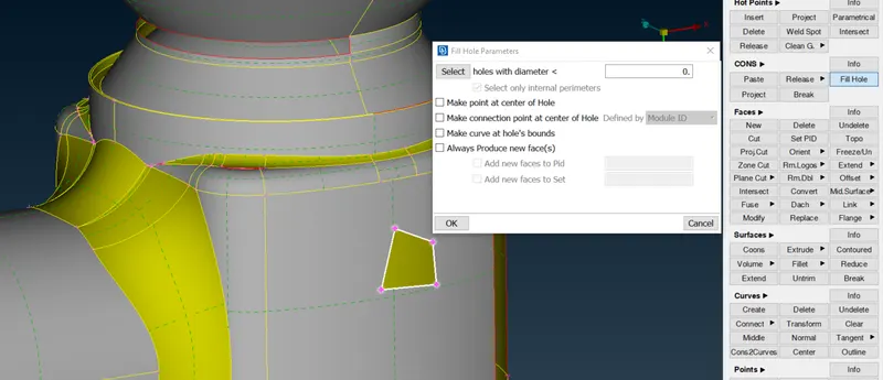
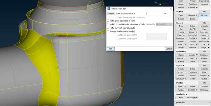
That's perfect, as no new surface formed, so we know how to use this tool for perfect face creation.
Moving to the next Red CONS:
Using the 'Fill holes' method:
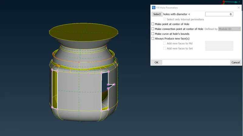
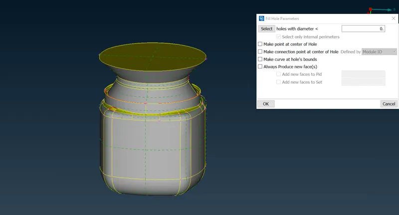
Post the middle mouse button click we can see we have created the faces, to get a visualization more accurately, we can even use NOT to hide some surfaces and check whether the surface which has been created by us is okay in geometry or not.
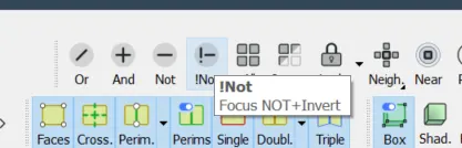
Selecting the place of the Pressure valve to get more clarity
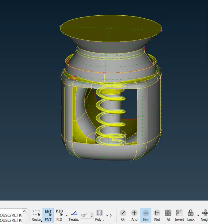
Views of both side faces which have been created:
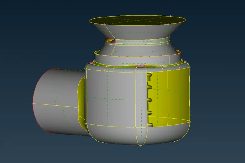
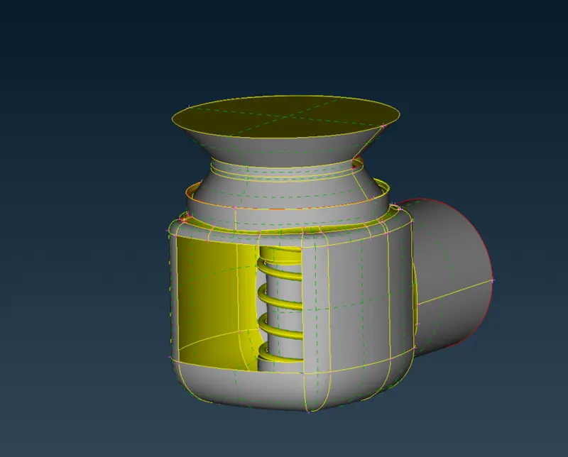
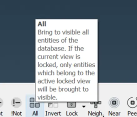
So, they look OKAY for going ahead, let's use ALL for getting back the hidden surface of the Pressure valve.
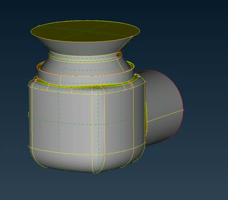
We always remove the red cons by considering the concept behind removing the error.
We should always keep in mind that our purpose or the concept of geometry doesn't get hampered due to misjudgment or error in removing surfaces from our end.
For example, if we remove the shown CONS by fill holes method see what we are experiencing.
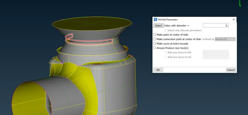
Removing the top surface for getting an idea of what surface we are creating:
Isometric view:
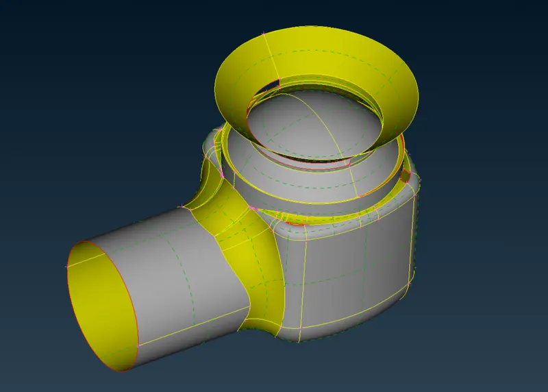
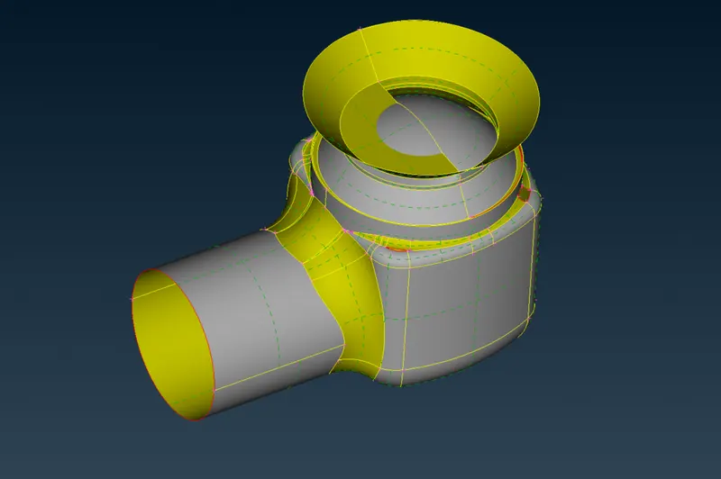
This surface will not serve our purpose as it is covering the dome and the purpose of the pressure valve is getting restricted.
Let's make the coons selection method a continuous selection of loop as it will be good if we can select the whole loop of CONS in a go.
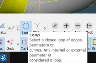
We will use the Loop method selection to get the complete loop in one go.
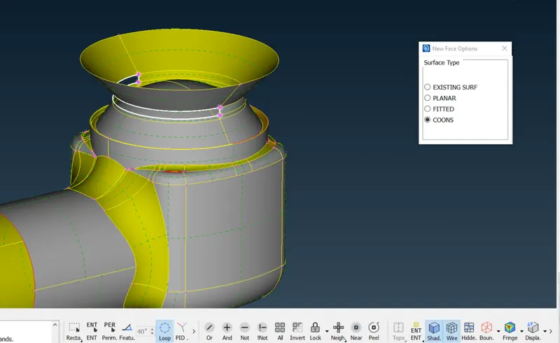
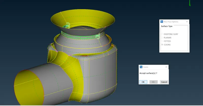
If we go for the planar surface in fixing this CON:
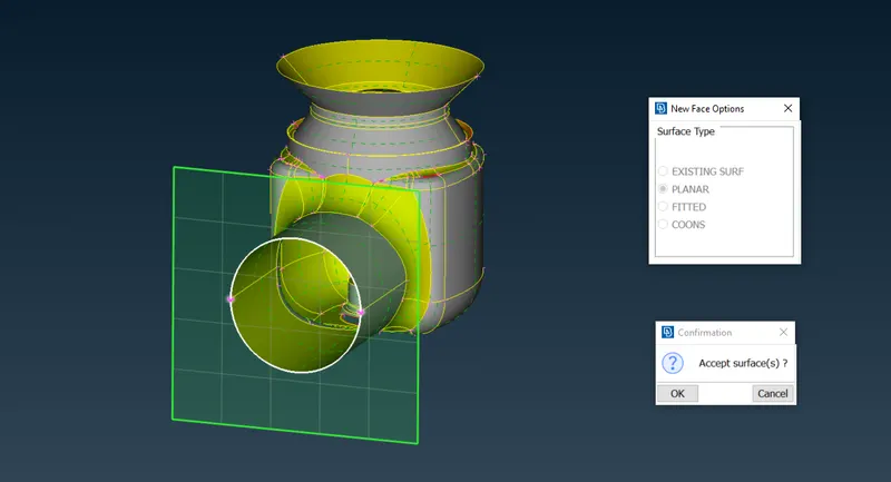
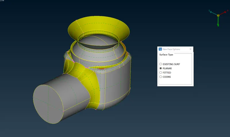
We will get an optimum surface as per geometry but, in the case when we don't have perpendicular faces or edges then this plane cannot solve our problem.
So we can use Fill hole also or even use COONS also for removing these errors.
Let's use some fill holes option and remove other Red Cons.
Using Fill Holes:
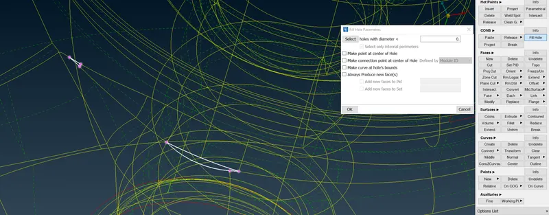
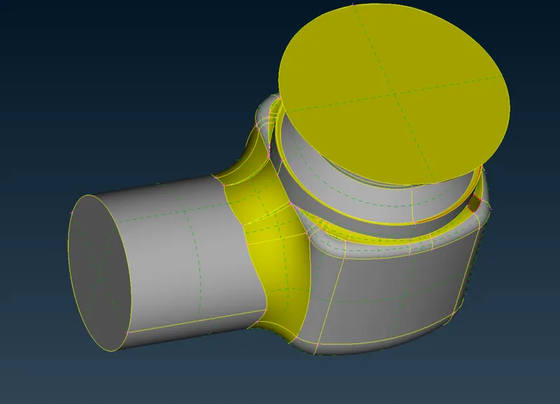
Fixed those, moving ahead, but we have seen there is not a perfect creation so we will be deleting the extra face which we found out after deleting one look.
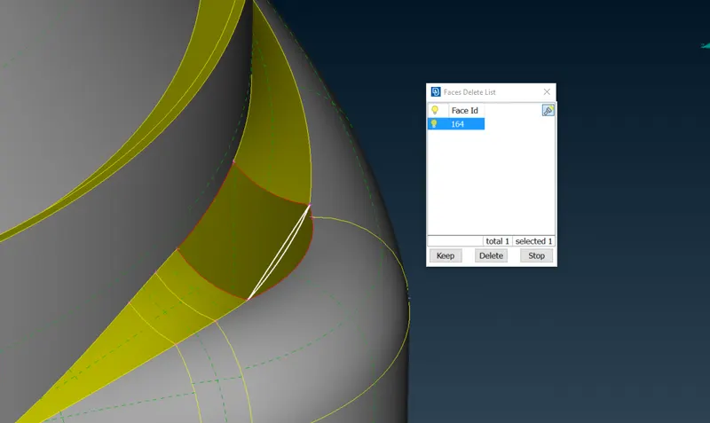
We can use Fitted also for cleaning the face as
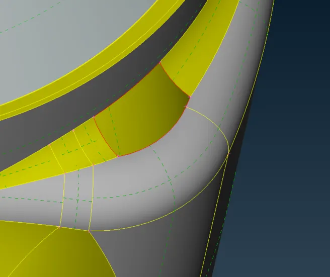
Using COONS
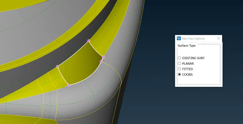
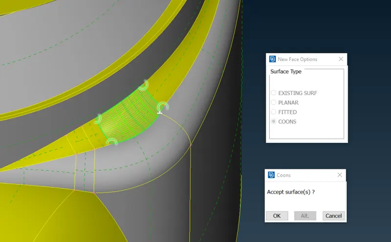
Here is the new face we have made.
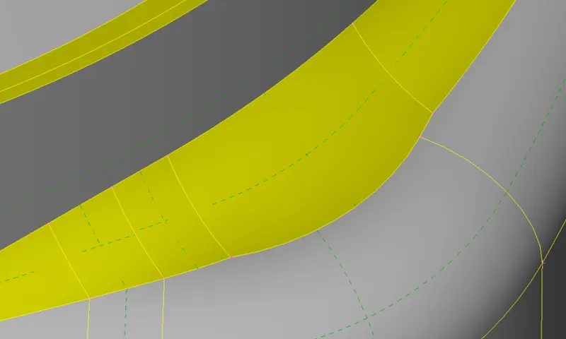
Now we can see some more red cons are available as:
Using Fill holes:
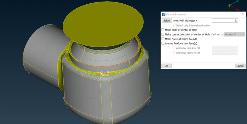
Still, we can find 2 red cons, let's clear them also:
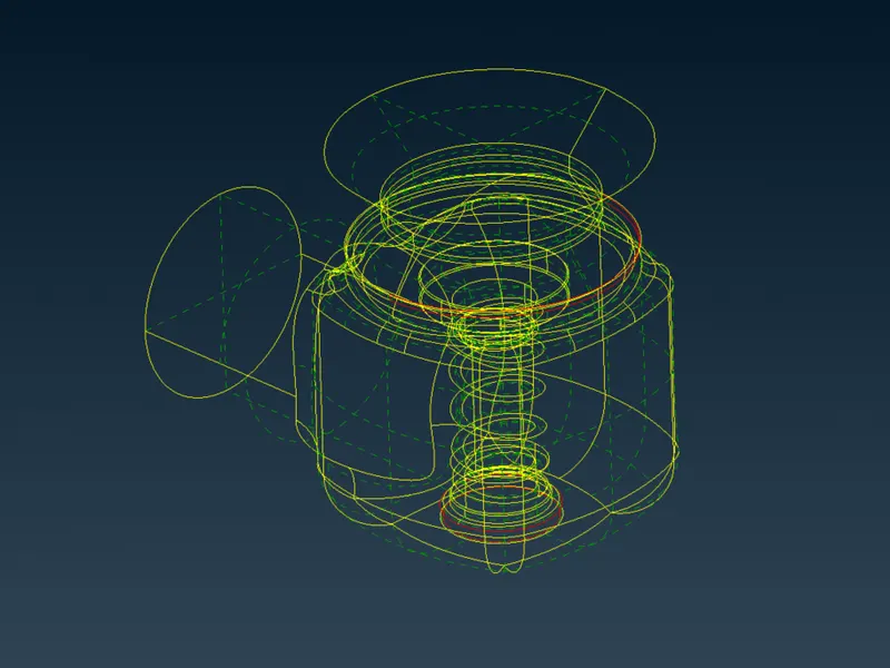
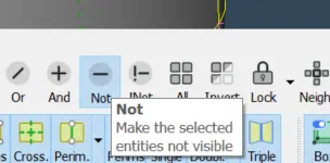
Use the 'NOT' option after hiding the surface.
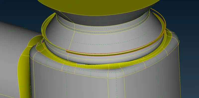
We will have to use COONS for fixing the red cons in this part as the 'fill holes' method will not work here.
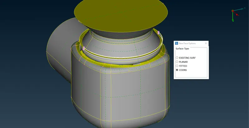
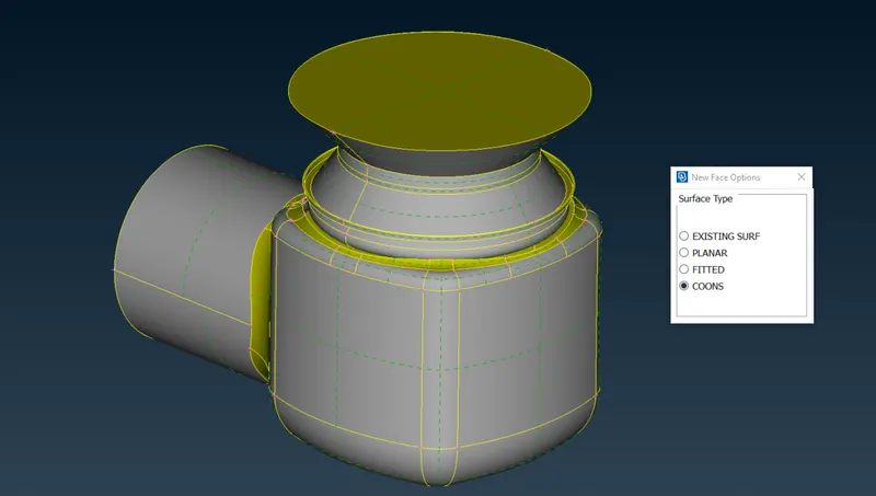
Use 'ALL' for getting the hidden faces back.
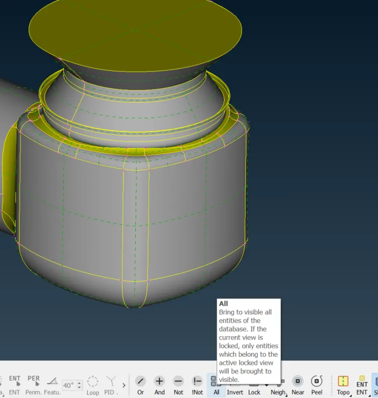
One more 'red cons' can be seen in this geometry as:
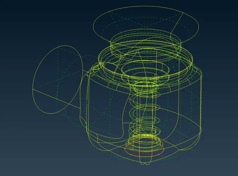
Let's hide other surfaces for getting the only surface which we have to work on:
Use the 'NOT' function
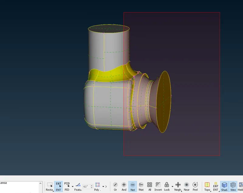
Doing BOX SELECTION on the geometry.
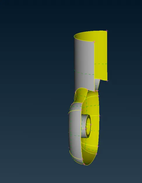
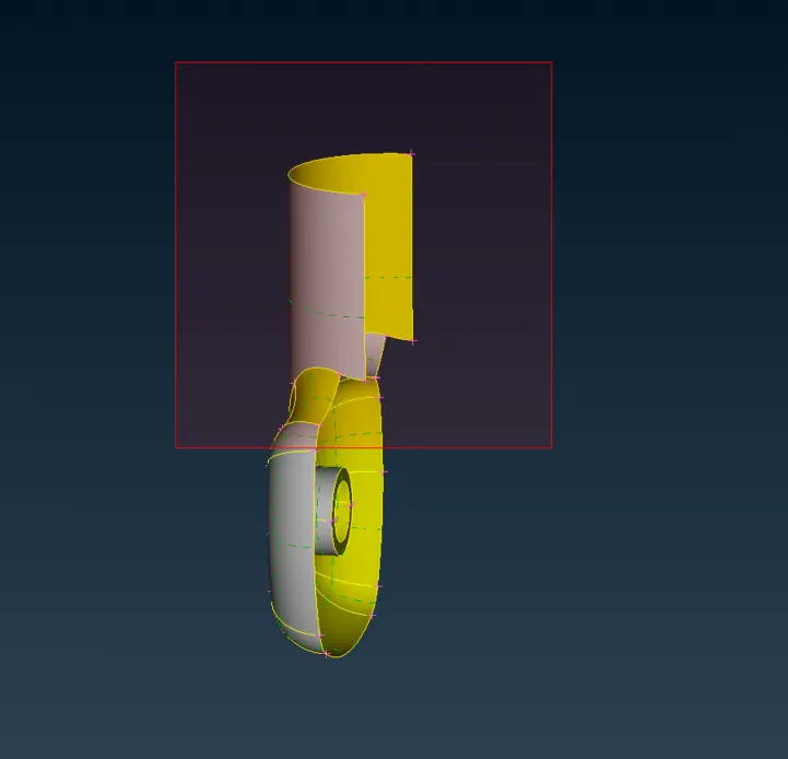
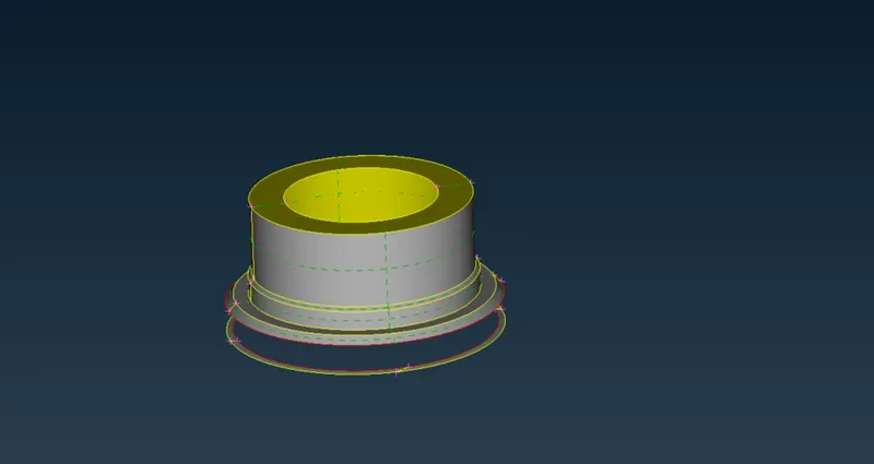
Now use the LOCK button to not get damage the original geometry while working on this part.
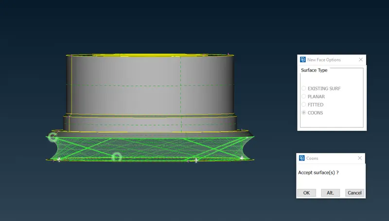
If we select both Cons we don't need this surface.
So we will use the entity selection method and use parallel cons for creating proper surfaces:
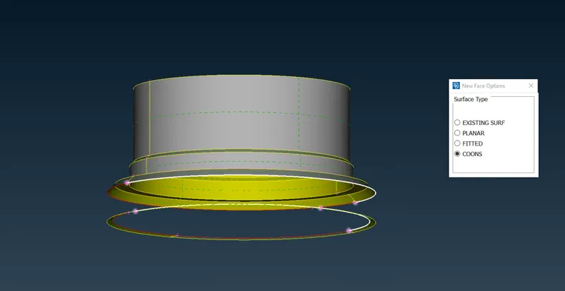
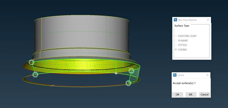
the other part:
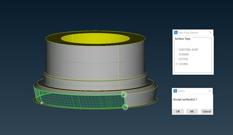
Removing the LOCK button and getting the complete geometry back:
Post doing all the fixing we can check the Geometry by Geometry check.
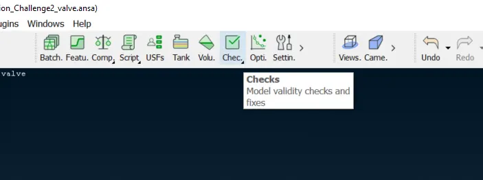
opening Check manager
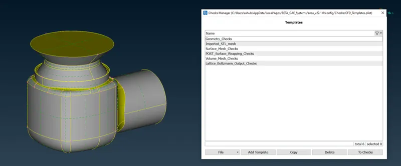
Post executing both the checks we get:
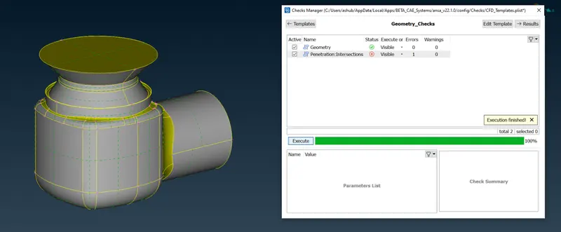
There is one Intersection error which we can check by using wire mesh mode and see where the error is:
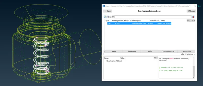
So now, we have to give PID (property ID) for complete geometry for getting into intersection errors.
Let's move to PID mode.
We got an error for ANSA to let's save and restart:
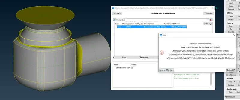
Okay restarted. Let's proceed ahead!
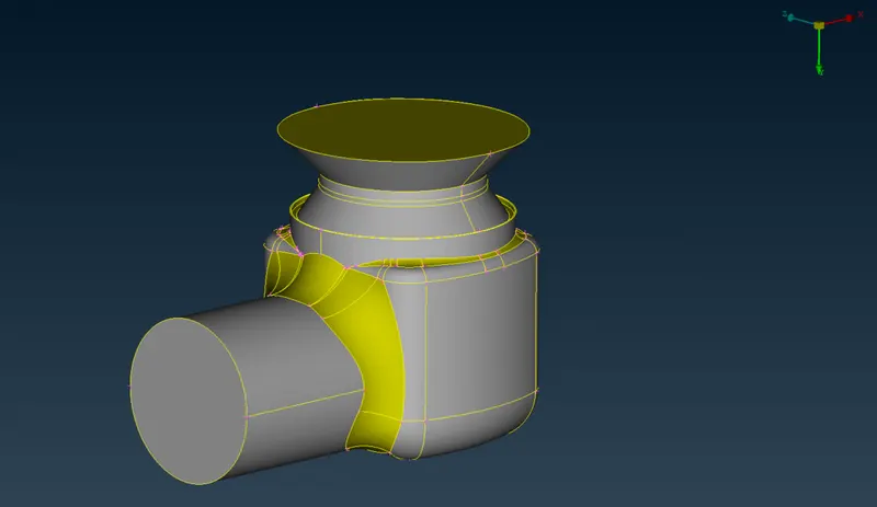
Let's assign the PIDs for individual parts.
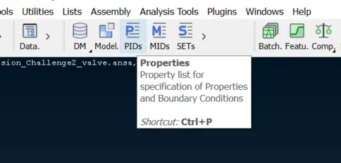
We need to change to PID mode to view the geometry in this mode:
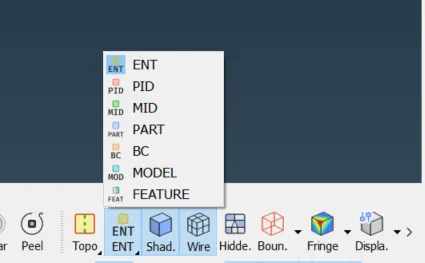
Enabling PID mode we will be seeing this:
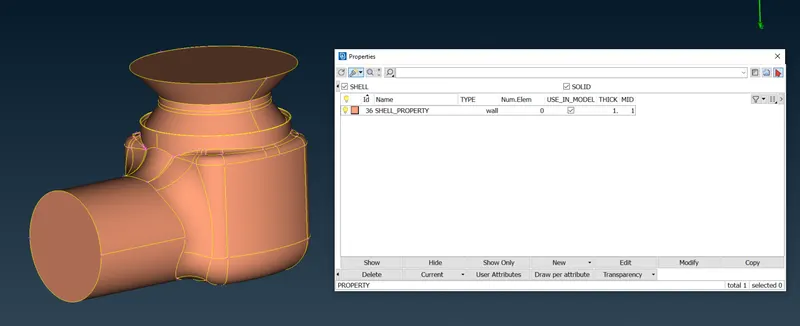
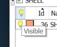
The Bulb symbol represents the visibility
Let's assign different parts of PID as different PID
Do Right click and use New Shell Property for the creation of a new PID
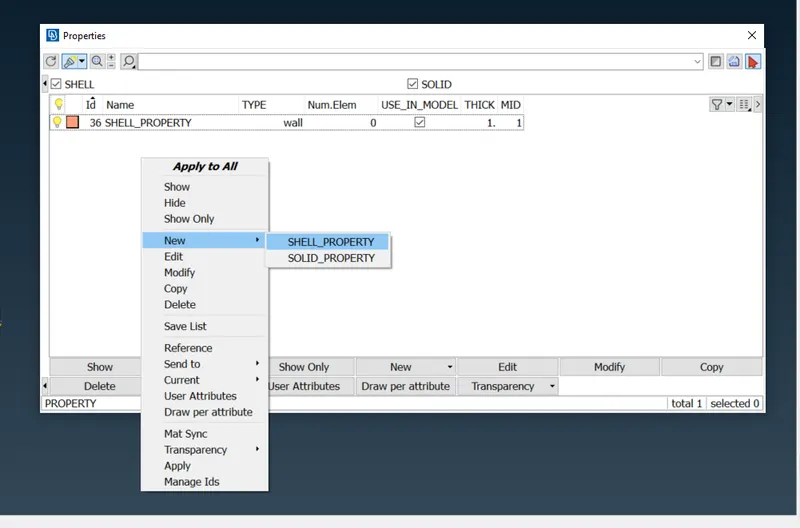
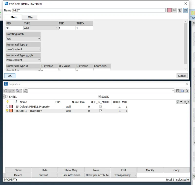
Currently, The Bulb is OFF as we have not assigned any component of geometry to the new PID made.
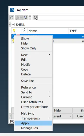
Use Apply to add the component, then select the face where we want to apply the PID
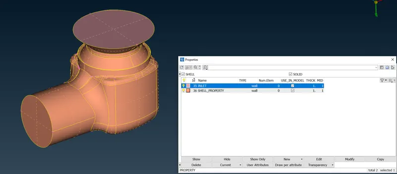
We can now hide the component by just clicking on BULB
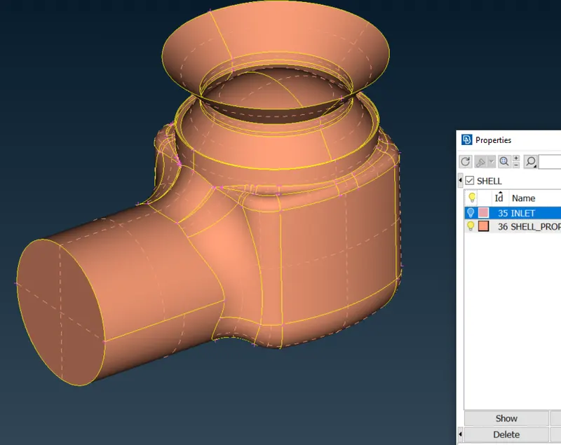
Let's assign more PIDs
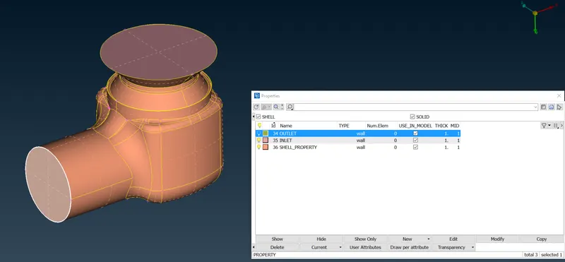
Post assigning we can see:
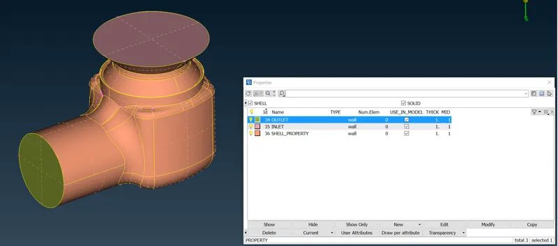
Now let's assign other components wherein we can add Body, Spring,
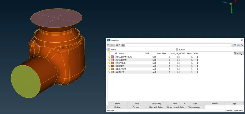
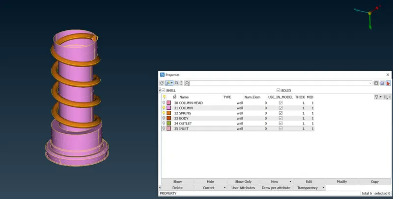
Post assigning we will find the table as this and the parts are as mentioned:
Lock the cleared geometry
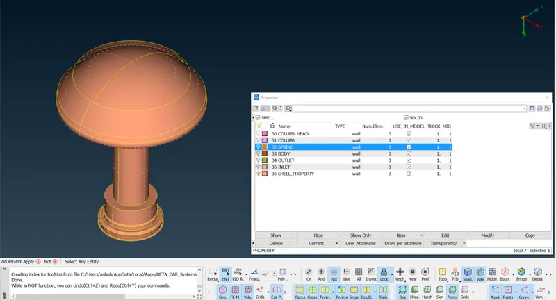
Here is the assigned PID model:
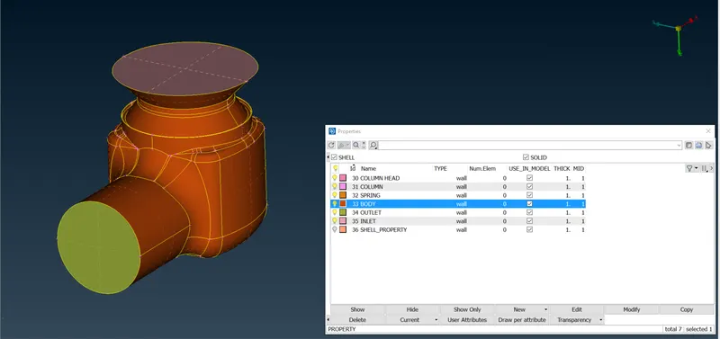
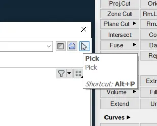
Enabling Pick option for getting an idea for assigned area.
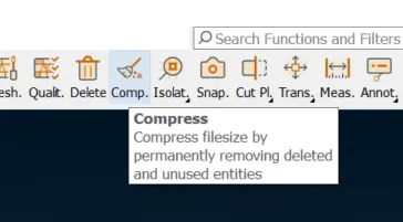
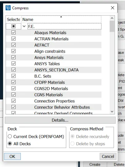
As the Shell property is not being used so we can delete it, so we will compress the same for better results:
Click OK
We removed the Shell property "WoHoo!"
Now let's move to Intersection errors:
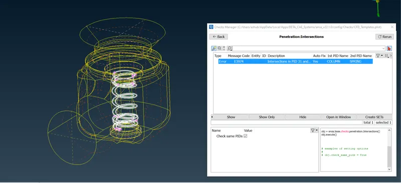
Isolated the required component like spring and column:
We can see we have a heavy intersection error as can be seen:
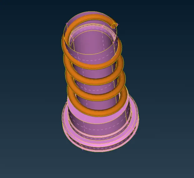
We will be using the intersect tool for clearing this kind of error.
We will get multiple faces with options to remove and keep the surface as per the output from Intersect tool.
Post doing clearing all the errors in 1st stage again we got stuck as we are not able to remove the error of spring intersecting the Column at the topmost part.
So, now we will reverse the selection of 1st and 2nd faces for the INTERSECT tool.
Fixing these errors we will be looking for any other errors left or not by doing the ' Geometry check'.
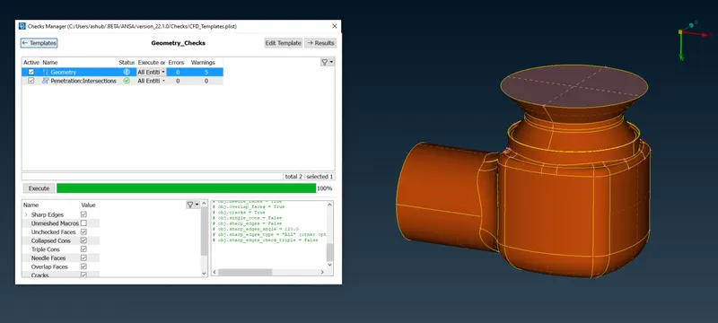
We have only convex errors left in the geometry.
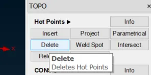
So delete the extra Hot points first.
So we will be going ahead with Meshing.
But before going ahead with Geometry meshing we need to fill this Hole:

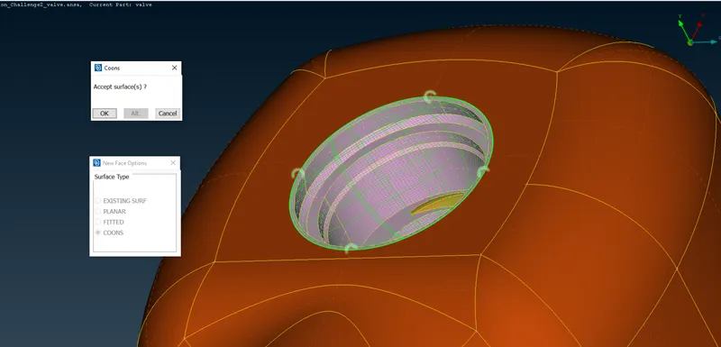
Fixing this we get a triple CON at that surface but since we require that surface for geometry meshing we will be keeping that in the geometry.
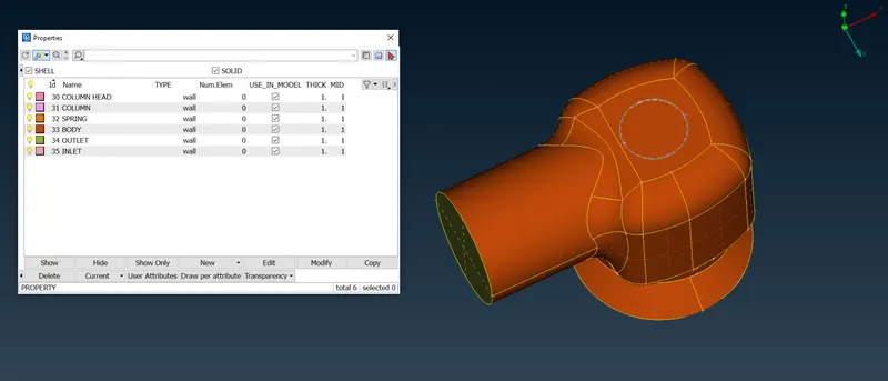
pOST FIXING ALLL THE ERRORS WE WILL GET THIS GEOMETRY AS SHOWN BELOW:
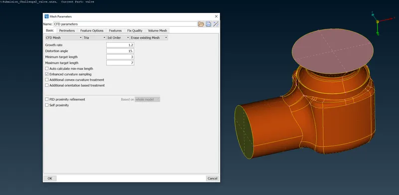
We have the objective of 5mm, 3 mm, and 1 mm length of mesh for Mesh quality.
So we will be defining some range for mesh length.
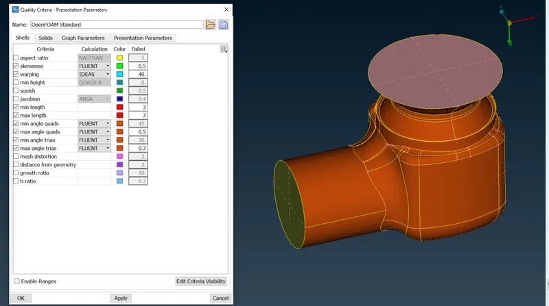
Let's give a range of 3-7 mm.
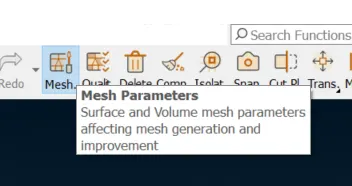
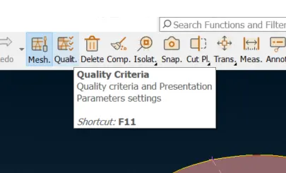
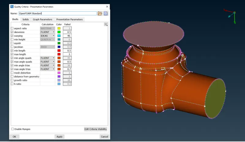
Let's go to the quality criteria and check the values of a minimum length of mesh
Apply my conditions for mesh length.
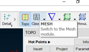
Let's go to classic Mesh mode
Check the length parameters for the geometry.
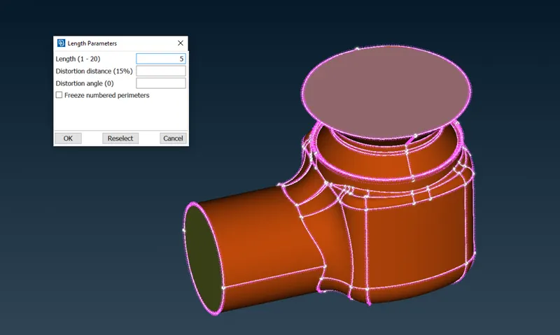
Check the same length parameters for macros also:
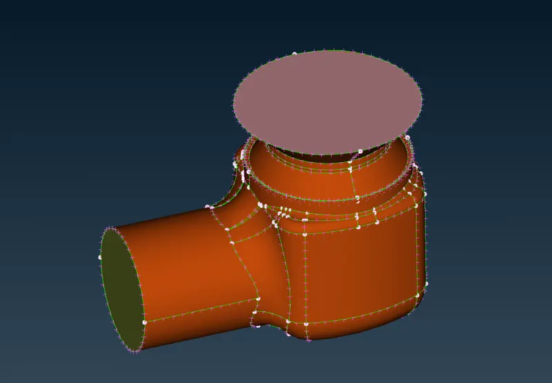
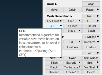
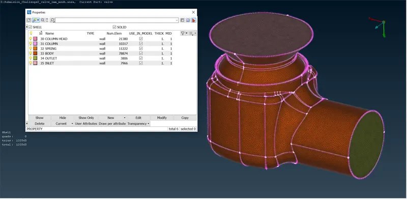
The mesh comes like this:
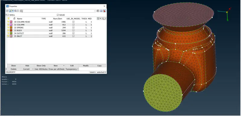
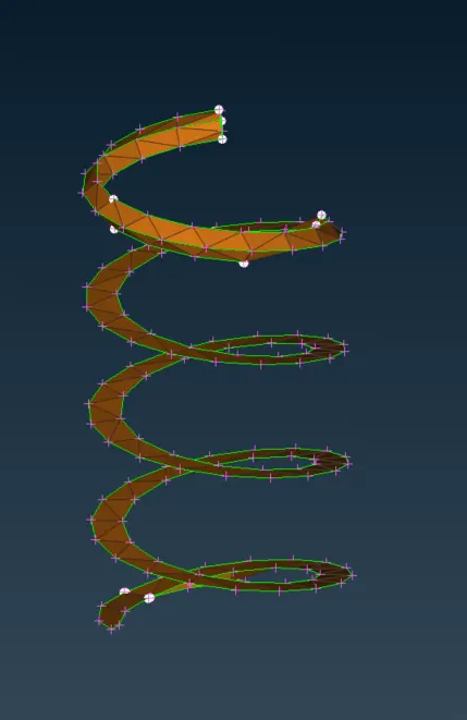
When we give the criteria for 3 mm then the mesh comes like this:
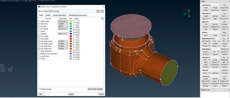
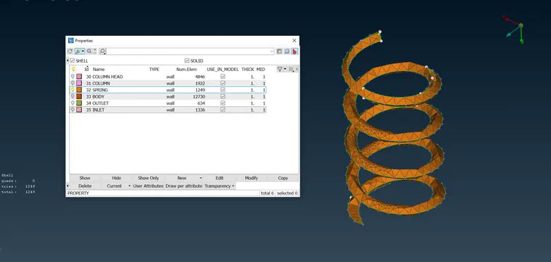
This mesh is also not suited so we will be saving the file and then moving ahead with 1 mm mesh now.
change the maximum length to 2 mm.
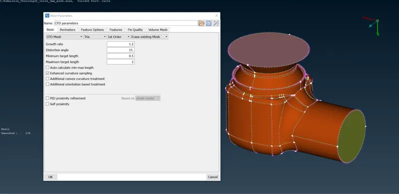
Change the value for quality mesh also
Change the length value in perimeters and macro:
Checking the spring part, we are seeing a better refinement of the mesh.
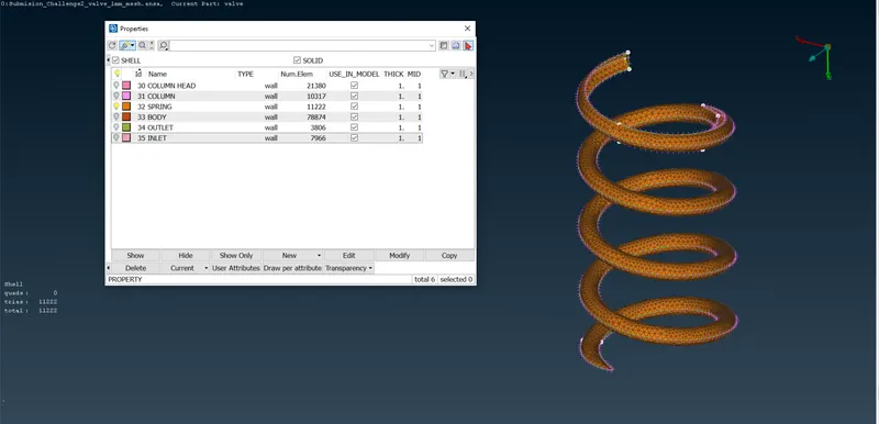
We can also mesh individual components with different mesh quality criteria, which also we learned in the tutorial.
Result, Conclusion.:
The file after meshing has been attached to the document. We completed the meshing of the Cylinder as per requirement.
"Submision_Challenge2_valve_1mm_mesh"
"Submision_Challenge2_valve_3mm_mesh"
"Submision_Challenge2_valve_5mm_mesh"
Conclusion: We learned the basics of ANSA software and also did our assignment for Week 2 for Pressure valves.
Thank you.