CFD meshing on Turbocharger
CFD meshing on Turbocharger
Objectives
For the given model, check for the geometrical errors to make appropriate volumes. Create and assign PIDs as shown in the video. Perform surface mesh with the given target lengths as per PIDs.
- Blade stage-1 = 1 mm
- Blade stage-2 = 1 mm
- Impeller = 2 mm
- Shaft rotor = 1 mm
- Turbo casing = 5 mm
- Compressor casing = 5 mm
- Inlet casing cover = 5 mm
Introduction
In an internal combustion engine, a turbocharger (often called a turbo) is a forced induction device that is powered by the flow of exhaust gas. It uses this energy to compress the intake gas, forcing more air into the engine to produce more power for a given displacement.
The current categorization is that a turbocharger is powered by the kinetic energy of the exhaust gas.
Like other forced induction devices, a compressor in the turbocharger pressurizes the intake air before it enters the inlet manifold. In the case of a turbocharger, the compressor is powered by the kinetic energy of the engine's exhaust gases, which is extracted by the turbocharger's turbine.
The main components of the turbocharger are:
- Turbine – usually a radial turbine design
- Compressor – usually a centrifugal compressor
- Center housing hub rotating assembly
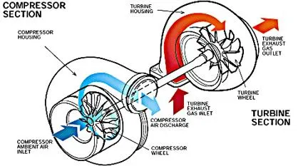
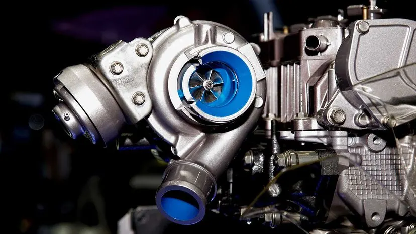
In this assignment, the geometry is simplified for learning objectives.
Working
A significant difference between a turbocharged diesel engine and a traditional naturally aspirated gasoline engine is the air entering a diesel engine is compressed before the fuel is injected. This is where the turbocharger is critical to the power output and efficiency of the diesel engine.
It is the job of the turbocharger to compress more air flowing into the engine’s cylinder. When air is compressed the oxygen molecules are packed closer together. This increase in the air means that more fuel can be added for the same size naturally aspirated engine. This then generates increased mechanical power and overall efficiency improvement of the combustion process. Therefore, the engine size can be reduced for a turbocharged engine leading to better packaging, weight-saving benefits, and overall improved fuel economy.
A turbocharger is made up of two main sections: the turbine and the compressor. The turbine consists of the turbine wheel and the turbine housing. It is the job of the turbine housing to guide the exhaust gas into the turbine wheel. The energy from the exhaust gas turns the turbine wheel, and the gas then exits the turbine housing through an exhaust outlet area.
The compressor also consists of two parts: the compressor wheel and the compressor housing. The compressor’s mode of action is opposite that of the turbine. The compressor wheel is attached to the turbine by a forged steel shaft, and as the turbine turns the compressor wheel, the high-velocity spinning draws in air and compresses it. The compressor housing then converts the high-velocity, low-pressure air stream into a high-pressure, low-velocity air stream through a process called diffusion. The compressed air is pushed into the engine, allowing the engine to burn more fuel to produce more power.
------------------------------------------------------------------------------------------------------------------
Procedure:
Import the geometry in ANSA.
Geometry
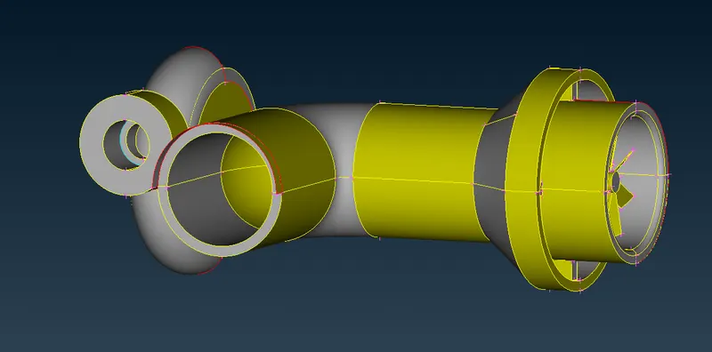
Swith to PID mode to view glitching surfaces (intersecting surfaces).
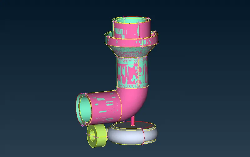
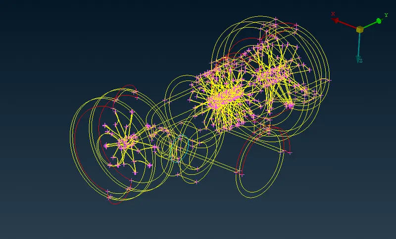
Glitch between Pink and Green surfaces can be easily identified. Now to idetify the red coons inside and outside the geometry, wireframe mode is enabled.
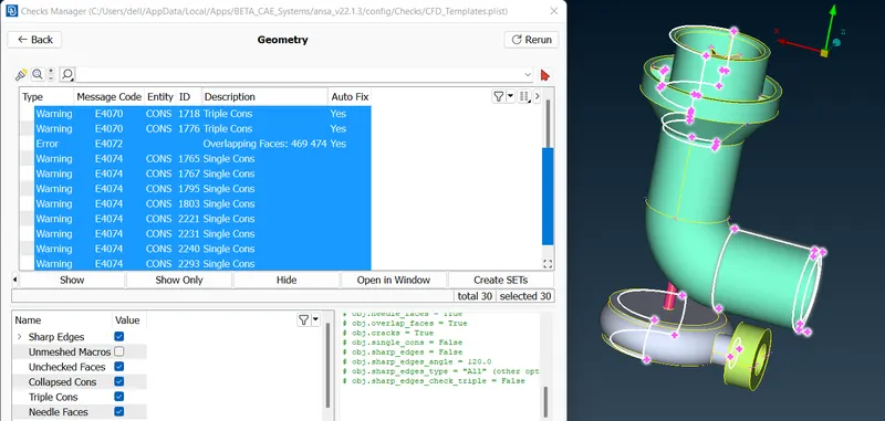
Go to the checks manager----> geometry check----> Execute----> Results. All the triple cons, intersections, single cons will be identified.
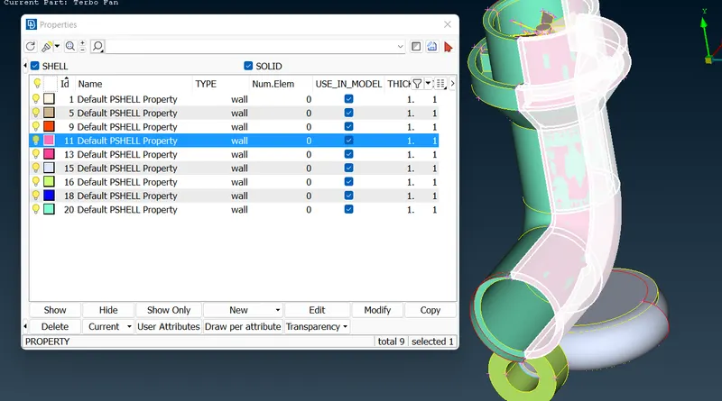
By disabling the pink PID from PID menu, identification could be done that the half part of compressor casing is present overlapping on compressor geometry. Delete pink PID.
Delete the extended face to inlet with red cons. After deleting this
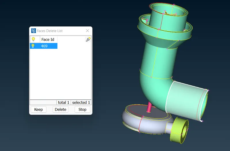
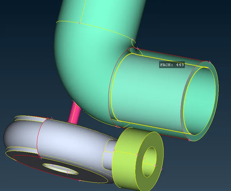
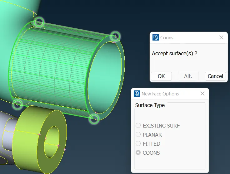
Deleted Face Add new surface by New-->Coons
Intersection can be seen but the boundary is not available here.
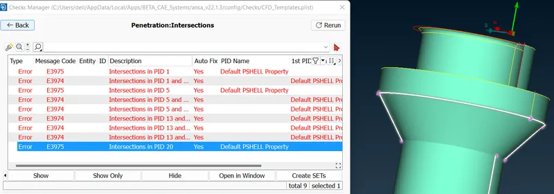
To create boundary we need to intersect there two surfaces and use cut option to remove the curvature present.
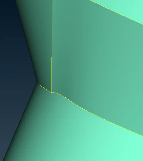
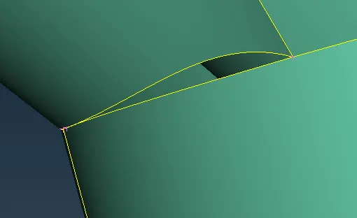
Edge formed by intersect under faces Use faces--> cut option to remove this curvy surface
Delete this surface and form a new surface.
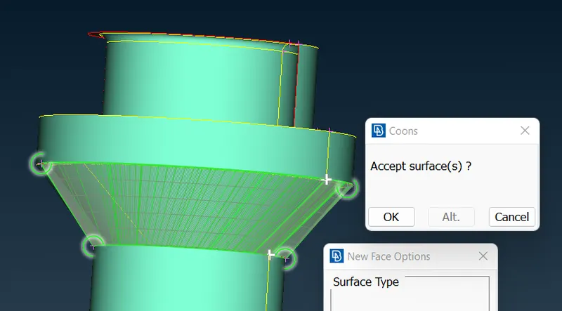
Next the red cone is cleared, the face is not present and if tried to onsert the new face by given algorithms of New---> Coons, then an intersecting face will appear as it is a complex cuve. Whenever a comlex curve is present then it must be made in small disintegrated types. It will not be possible to make it in one go.
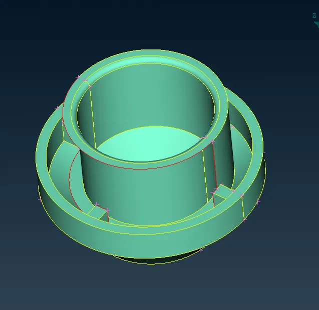
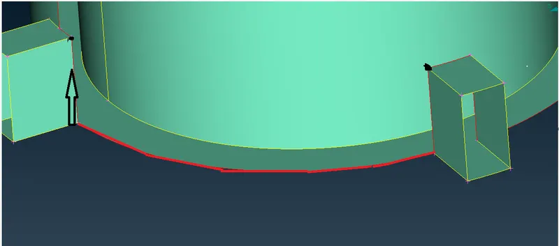
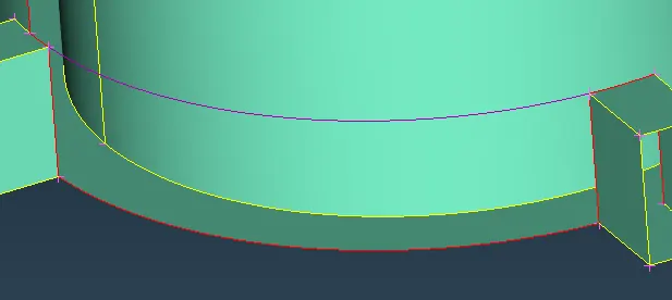
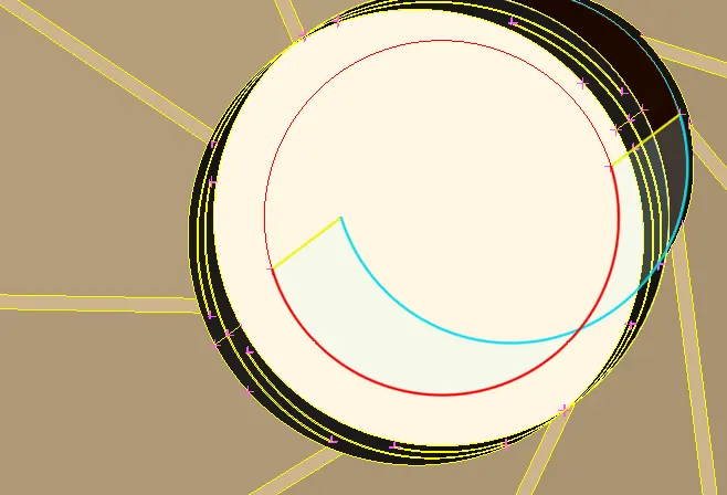
Different steps were used for making this face, first there was a need of curve to make a surface section, Curve----> Transform option is used. The red curve present below is selected using left click then confirm by middle click, Select the first point where the curve start as the second point is selected where the curve ends; projected curve appears in purple curve.
`darr`
`darr`
`darr`
`darr`
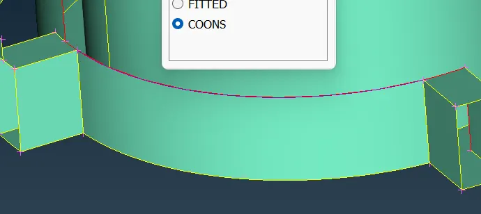
Use New---> Coons to form a surface then delete the curved edge after making surface. Do the similar procedure on the other side and finally join the remaining surfaces by Coons option.
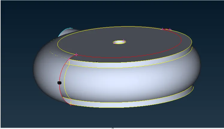
Next red cone is present at turbine casing, turbine casing is not covered by casing wall. It is also a complex curve therefore it connot be formed by available face forming options. This error in geometry is rectified by copying the opposite face available. For Copying the face, three points were needed. Two points are available are at edge ends and third point is inserted by using Hot Points---> Insert. Point was inserted just at the mid of open edge.
From top menu Utilities---> Trasform---> Copy is selected.
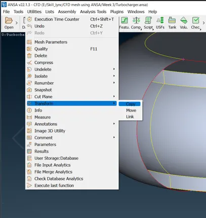
Use Entities option to Copy. Use Symmetry---> Mirror 3 points Plane and left click on the points about which symmetry option takes place. Coordinates of three points would appear in cartesian coordinates.
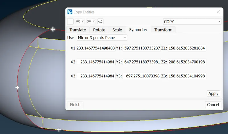
Click on Apply----> Transformation options dilogue box was appeared, no need to change anything click Ok----> Finish.
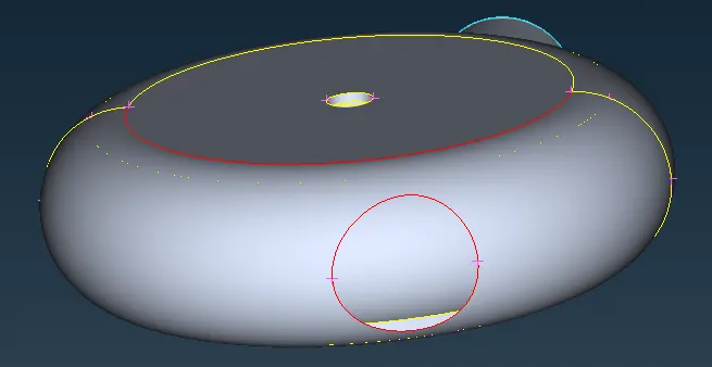
Fill Hole option can be used to clear the open edge.
Pack all the inlets, outlets and openings to properly apply CFD mesh.
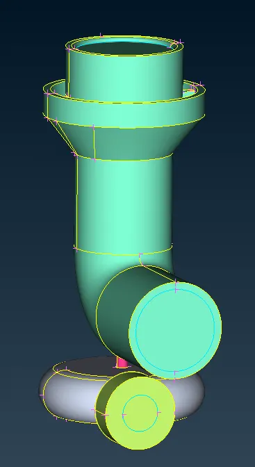
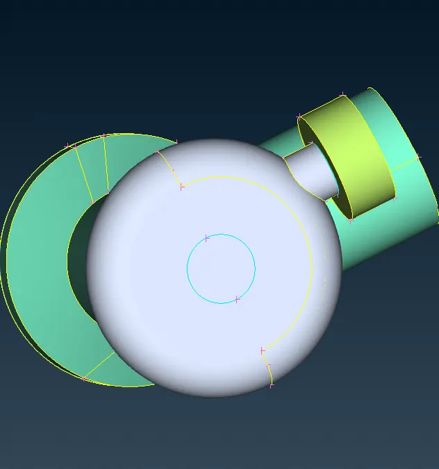
Fill all four surfaces which were open from top by coons option.
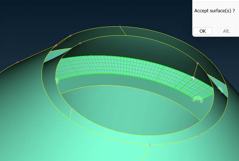
Now finally go to checks manager to check. It was found out that there were intersection errors present in the shaft-blades-impeller assembly. Now the preprocessing focus is shifted to the internal components.
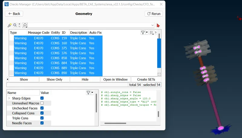
Clearing of triple cones were started by hiding impeller blades one-by-one using not option. The assembly was locked to save the current status of visible parts. All triple cons faces are cleared one by one deleting double faces using faces---> delete option.
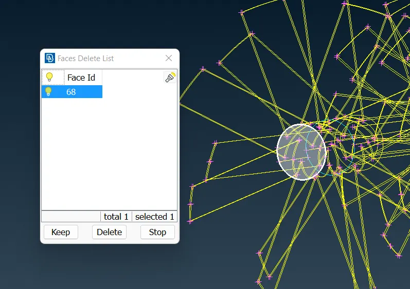
For clearing the intersection error with shaft delete the intersecting faces from shaft and blades. Then use coon option to join the open edges of blades as shown below.
Step-1 Hide all the extra blades.
Step-2 Delete intersection faces using faces---> Intersect option.
Step-3 Finished part must look like this.
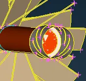
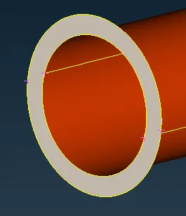
Step-1 Step-2 Step-3
Keep deleting the double faces.
To clear the intersection error shown below, the shaft which is inserted in the blade should be deleted upto the blade part. But it can be identified that there is no edge present on shaft to delete the shaft faces upto blade part. To make section use Face--> Cut option/ Intersection option/ Project CONS option.
In this report, Project CONS option is demonstrated.
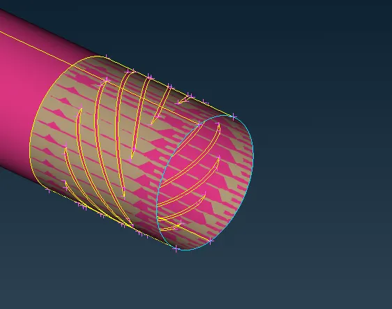
CONS---> Project. Select the edges to project on shaft----> Middle Click----> Select the faces on blades----> Middle Click. Edge would be projected successfully. Hide the blade surfaces using NOT option.
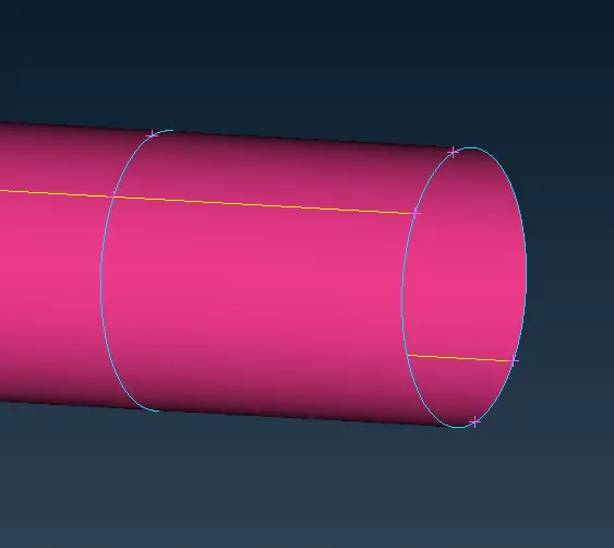
These blue COONS favces were deleted shown in the above figure.
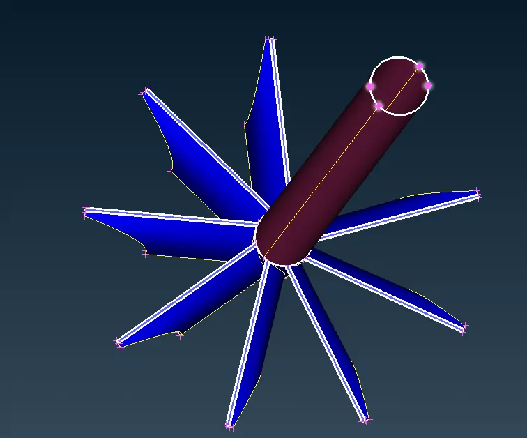
To clear the intersection error of impeller the center portion and blades need to be separated. To do so, the upper edge of shaft is projected on the impeller blade which breaks the centre portion of impeller from blades as shown in below figure. Delete intersecting faces.
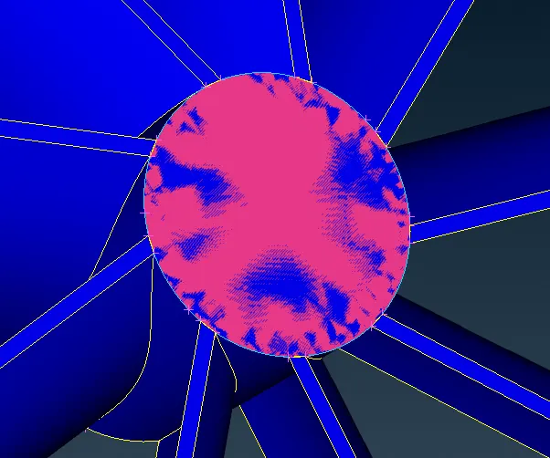
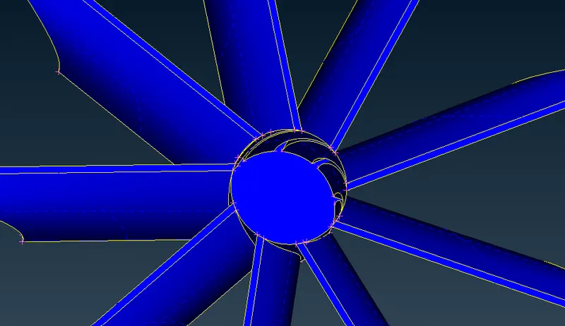
Enable Shaft-----> Do a TOPO to terminate red/single Coons.
Unhide all faces.
Run a Geometry check. In the geometry check two intersections were identified with compressor casing-shaft and turbine casing-shaft.
Delete the intersecting green PID faces.
The shaft was again deleted using CONS---> Project, select the cutting edge con, project it on shaft face--> Middle click--> Delete the intersecting faces.
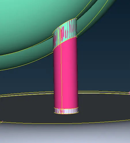
The shaft in the bulk material was needed to be deleted as it will not participate in CFD calculation.
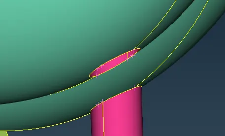
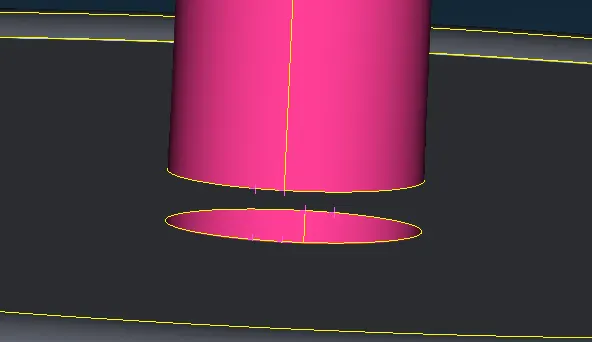
The extra orange shaft is part of the shaft body, intgrate this PId with Shaft PID and then delete orange PID.
In final check only warnings were present for triple cons, which were faces used to close open edges and couldnt be changed.
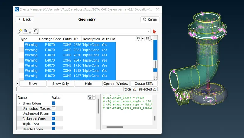
Meshing could be initiated after all checks are clear and no error message comes.
MESH GENERATION
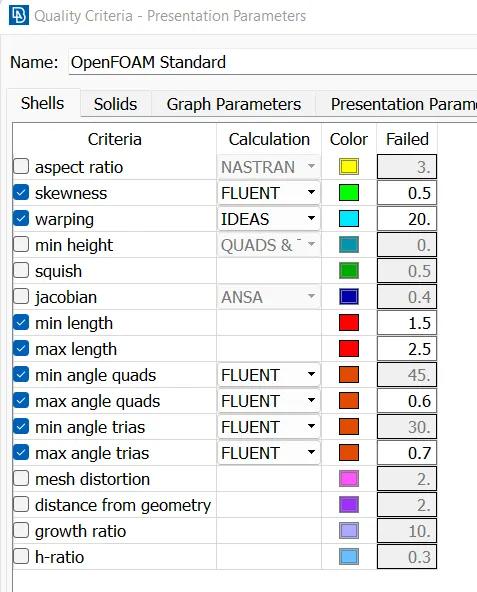
Given target lengths as quality parameter.
- Blade stage-1 = 1 mm
- Blade stage-2 = 1 mm
- Impeller = 2 mm
- Shaft rotor = 1 mm
- Turbo casing = 5 mm
- Compressor casing = 5 mm
- Inlet casing cover = 5 mm
Those objects which are having same target lengths should be present on screen, other objects would be hidden to assign target length simulataneously to all objects which had same terget length.
Starting with Blade stage-1, Blade stage-2 and Shaft rotor.
Target Length= 1
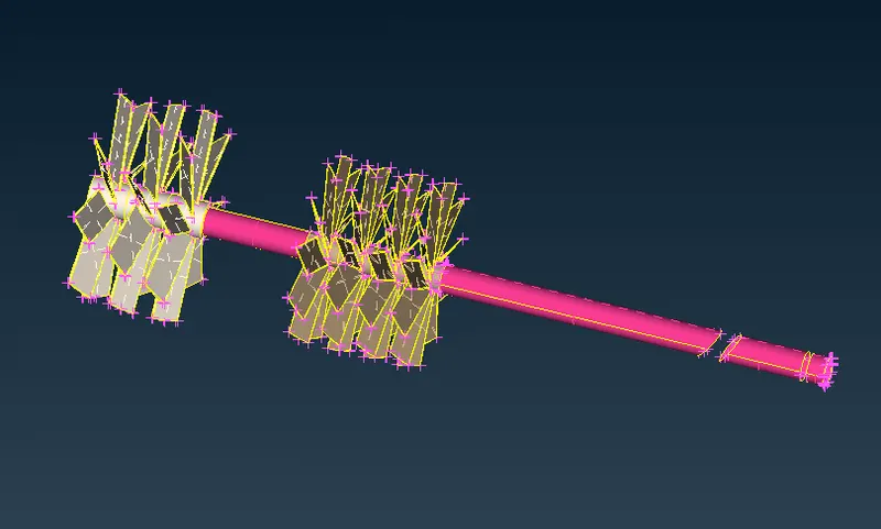
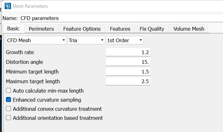
Give mesh parameters and Quality parameter as shown below. These values were changed as per the target lengths of geometries.
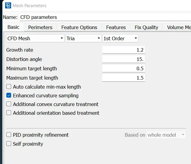
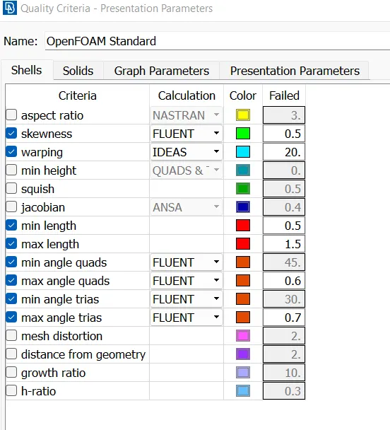
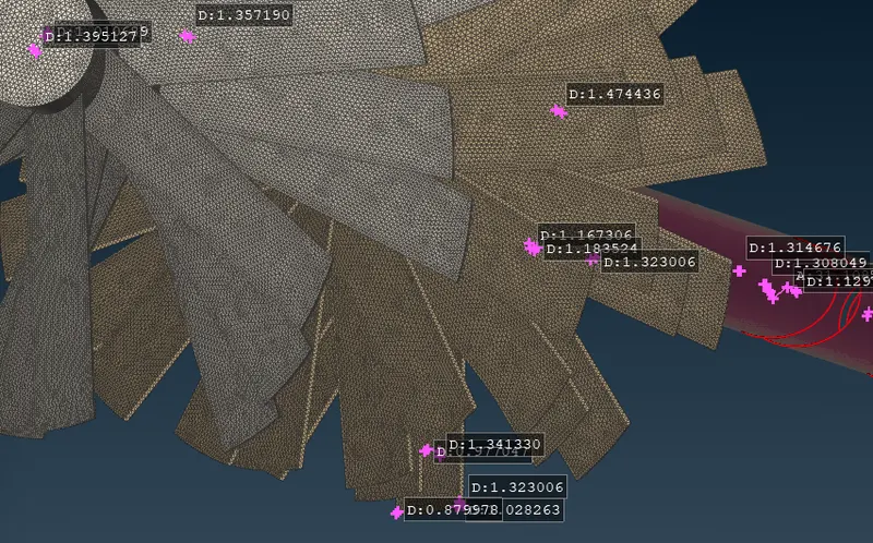
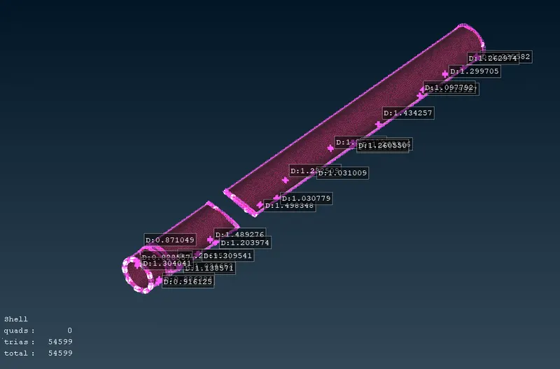
Classic Mesh--> Perimeters--> Length--> give macros and perimeter as 1. Red coons present will be cleared when transition mesh will be applied between shaft and casing.
---------------------------------------------------------------------------------------------------------------
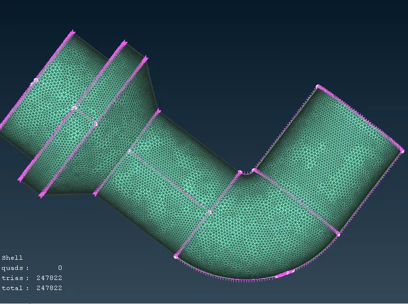
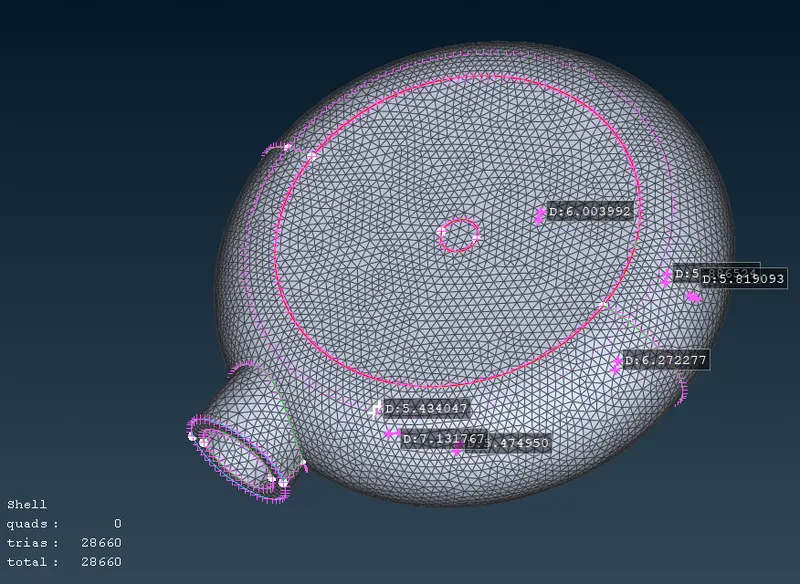
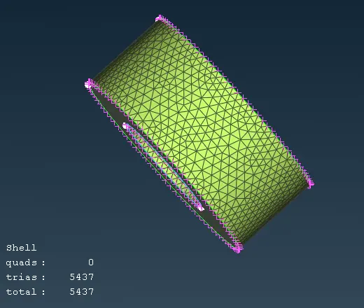
Target Length= 5
Compressor, turbo casing and inlet casing cover were activated for meshing.
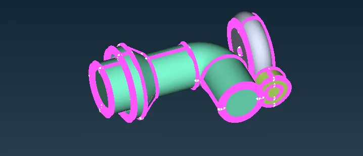
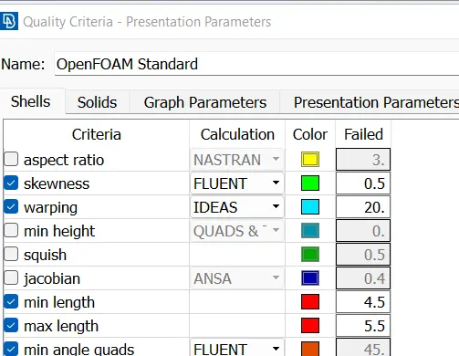
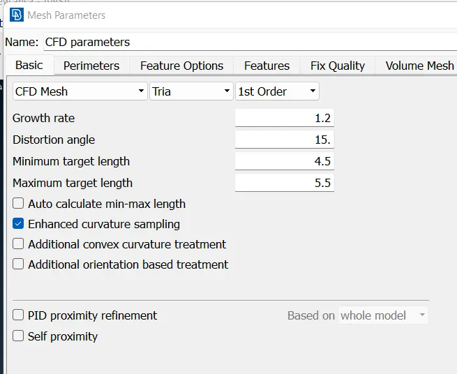
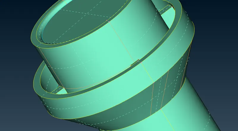
Remove unnecesary edges by using faces---> cut tool by right click, colour becomes orange with right click.
----------------------------------------------------------------------------------------------------------------------
Target Length= 2
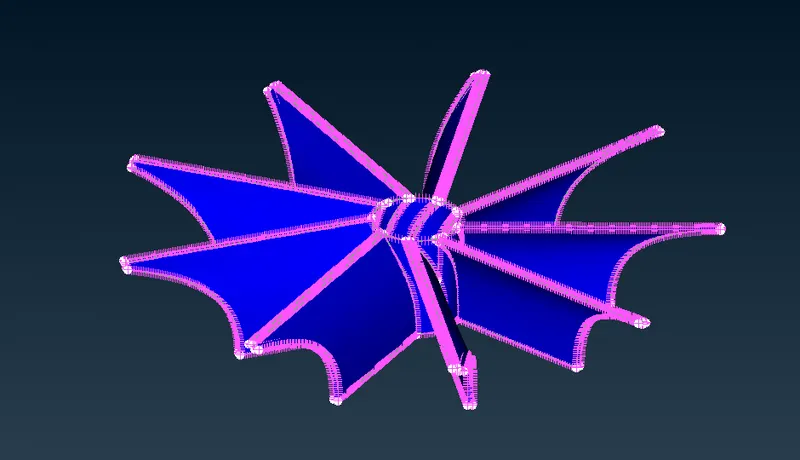
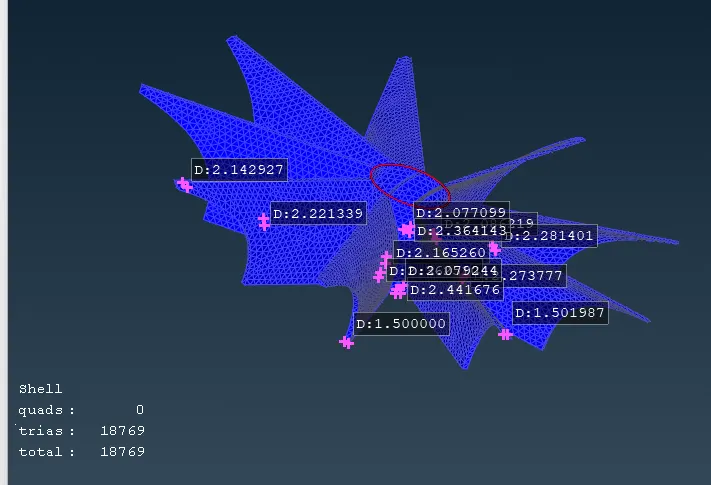
On impeller target length is assigned as 2. Impeller is isolated for meshing.
--------------------------------------------------------------------------------------------------------------------
Some parts mesh was erased due to the target length conflict on the boundaries. As the shaft target length is 1 while turbo-casing and impeller casing target length is 5, therefore free algorithm will be used to make a transition mesh which grows from shaft 1mm length to 5mm length of casing. Change the min-max length to 1-6 and assign target length to each component. Use free algorithm meshing.
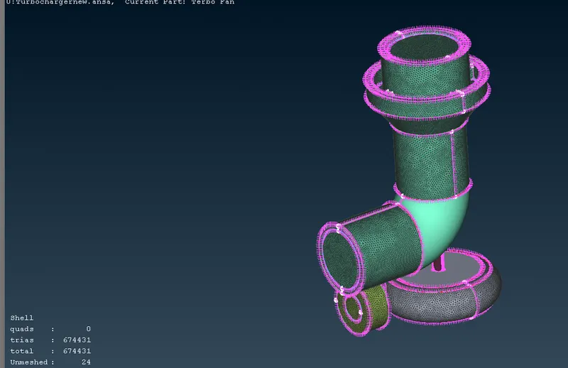
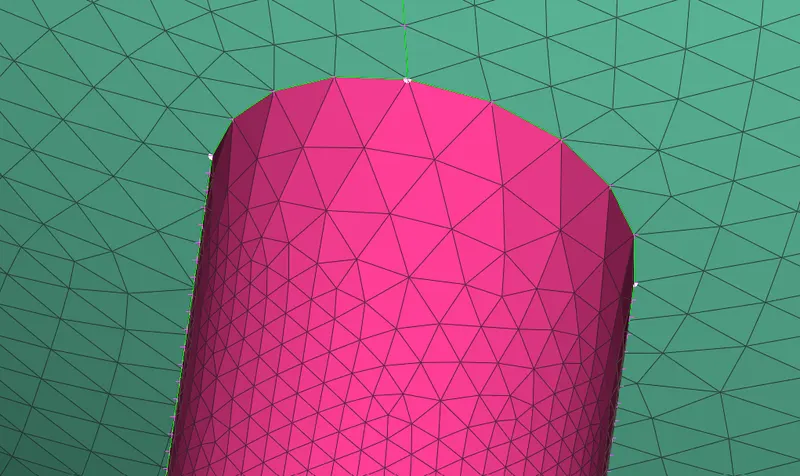
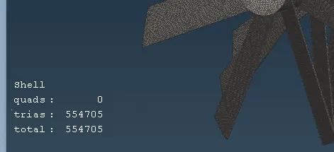
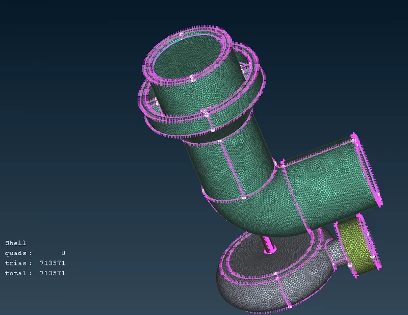
All bodies were surface meshed succesfully.
----------------------------------------------------------------------------------------------------------------------
VOLUME MESHING
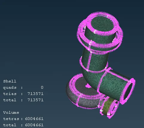
After preparing the surface mesh, the volumes of the model are defined using the Define tool in the Volume menu of the Vmesh toolbar and then all the unnecessary volumes are deleted. And the type of the volumetric mesh is defined as tetra CFD in the type section of the define menu.
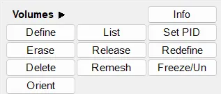
These highlighted volume were deleted. Use Tetra CFD mesh for the volumes, can apply one-by-one or simultaneously.
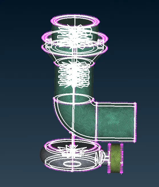
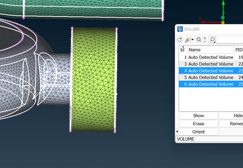
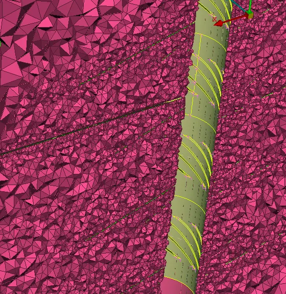
CUTSECTIONS
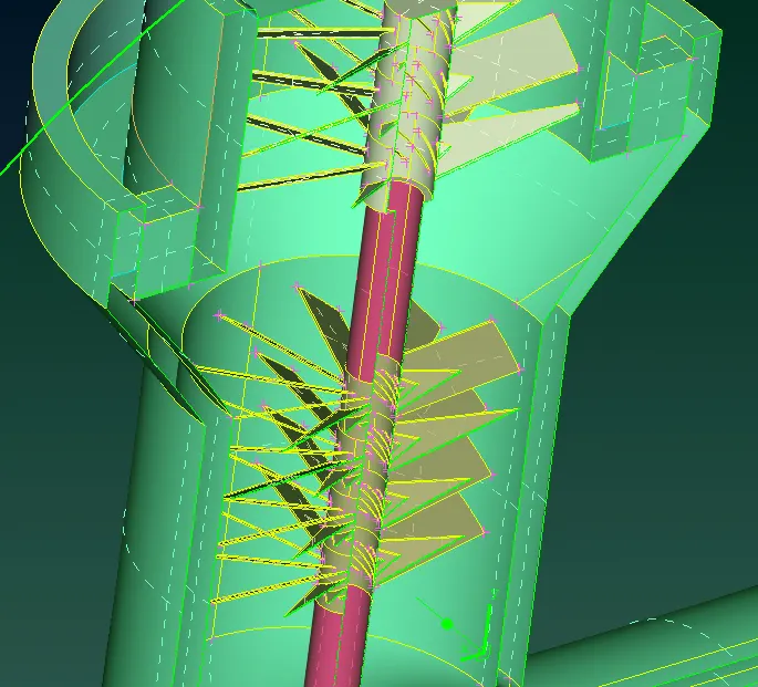
CFD MESH------------------------------------------->
Conclusion
Errors and warnings were cleared.
New tools such as curve transform and copy face were utilised to create and repair faces.
Openings were closed for fluid meshing.
Turbocharger Volume mesh was applied succesfully.
TETRA, CFD and free mesh algorithms were utilised for meshing.
Geometry link: https://drive.google.com/file/d/1oS5xYvz9fM7NC3zTVv34B5ksIRuUjaTB/view?usp=sharing
------------------------------------------------------------------------------------------------------------------
References