Week 3 Challenge : CFD meshing on Turbocharger
https://drive.google.com/file/d/1GCaqifnQTR0arCpEhHyP9mhSv16NUXqk/view?usp=sharing
https://drive.google.com/file/d/1GCaqifnQTR0arCpEhHyP9mhSv16NUXqk/view?usp=sharing
CFD MESHING FOR TURBOCHARGER
AIM
For the given model, check for the geometrical errors to make appropriate volumes. Create and assign PIDs as shown in the video. Perform surface mesh with the given target lengths as per PIDs.
- Blade stage-1 = 1 mm
- Blade stage-2 = 1 mm
- Impeller = 2 mm
- Shaft rotor = 1 mm
- Turbo casing = 5 mm
- Compressor casing = 5 mm
- Inlet casing cover = 5 mm
Perform Volumetric mesh for the required volumes.
PROCEDURE
1. Topo mode check for geometrical errors and clear geometric and intersection errors.
2. assign pid for every part.
3. Classic mesh. surface mesh is done for every part for the given target length and complete the surface mesh.
4. Volume meshing we need to perform volumetric mesh for the internal volume of turbo charger.
I will upload the procedure in screenshot and explain completely one by one for good understanding purpose.
opening the turbocharge ansa file
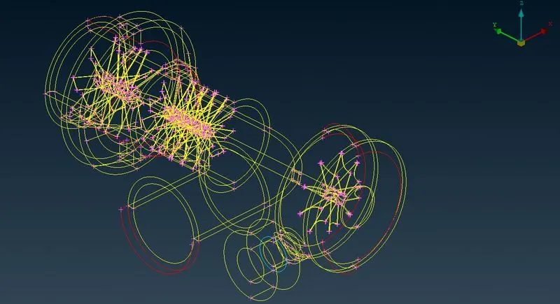
this is in wire frame mode now we see in shadow mode by selection the shadow mode and ent mode.
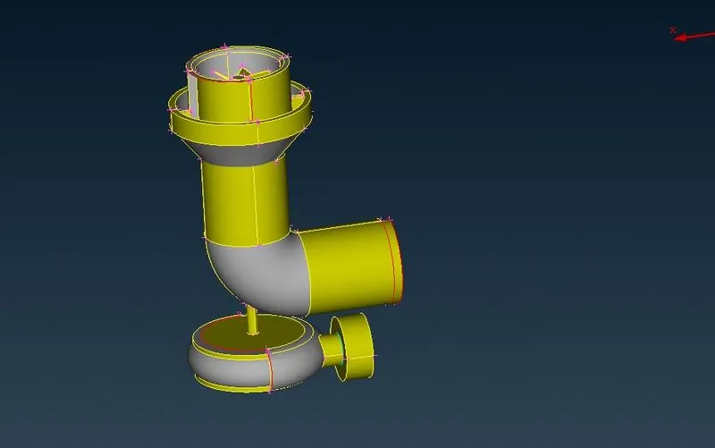
in this we can see the red cons and triple cons we have to clear one by one to clear all the geometric error and glitchs.
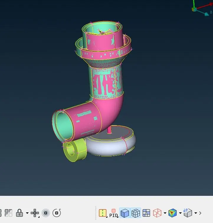
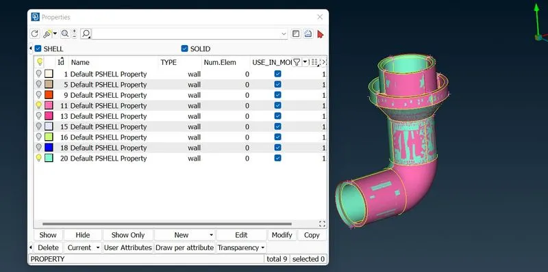
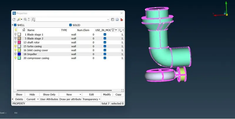
this are the already assigned pid for the turbo charger. now we are going to remove the glitch from the chamber shown above.
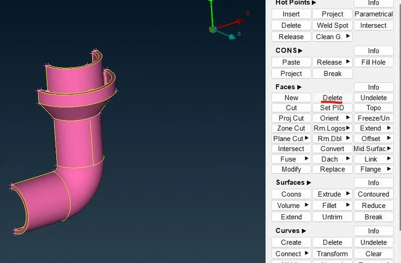
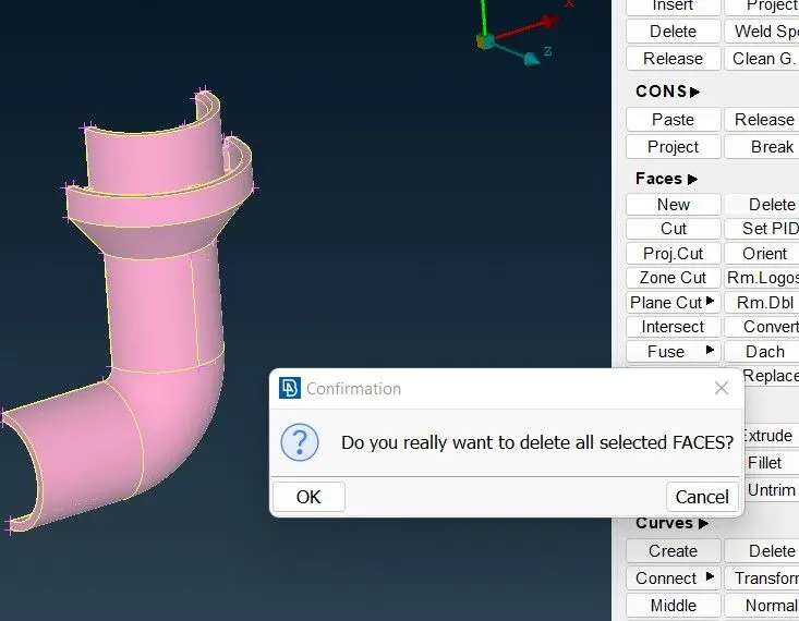
the another surface hidden in the pid is removed.
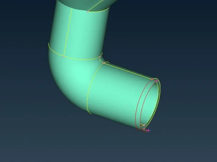
the glitch is removed now we have to remove the red cons from the geometry.
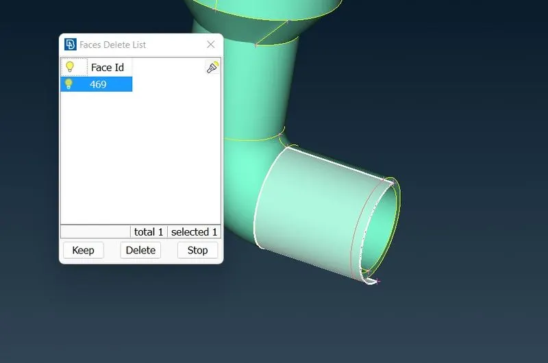
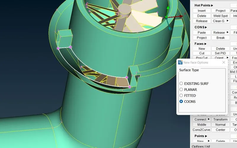
we have to delete the surface and we can create the surface using coons.
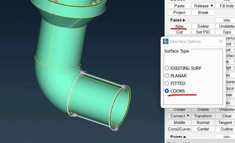
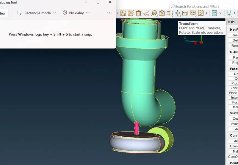
now we gonna insert a point and we gonna extrude the shape of turbo casing by three point symetric method.
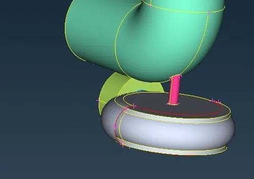
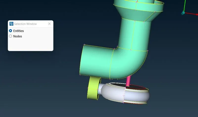
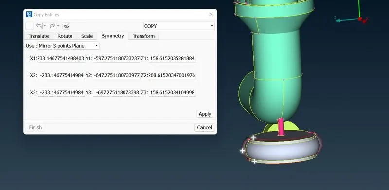
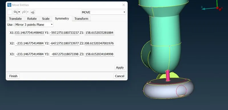
now close the hole using fill hole.
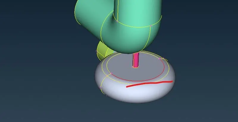
by using topo we remove the red cons.
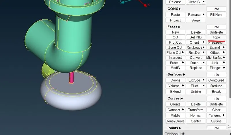
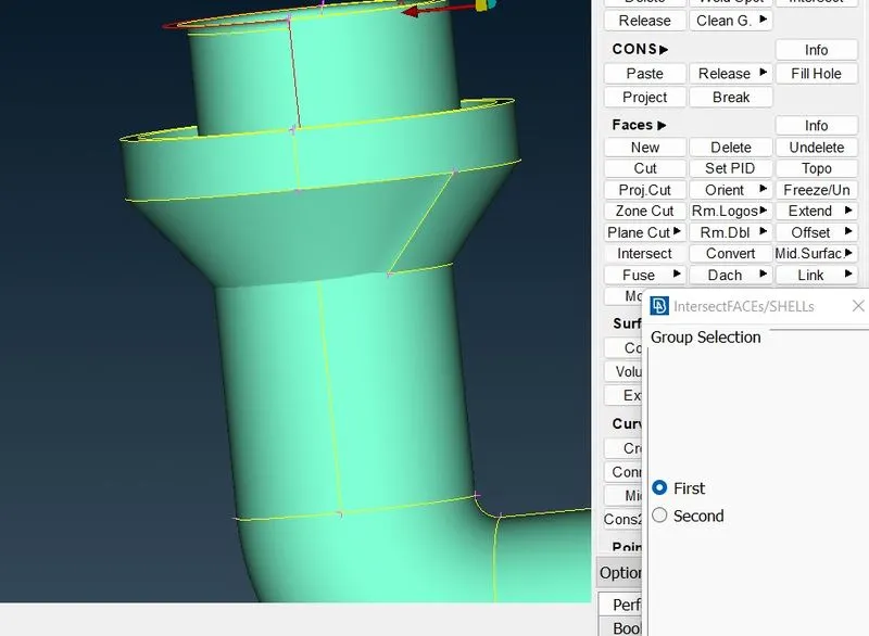
now we are into intersection error we gonna clear it using intersection option first we chose the first entity and next we chose the second entity so it combines and form a complete. then we can delete some hot points which made while intersection. then we have to clear the shape of the body.
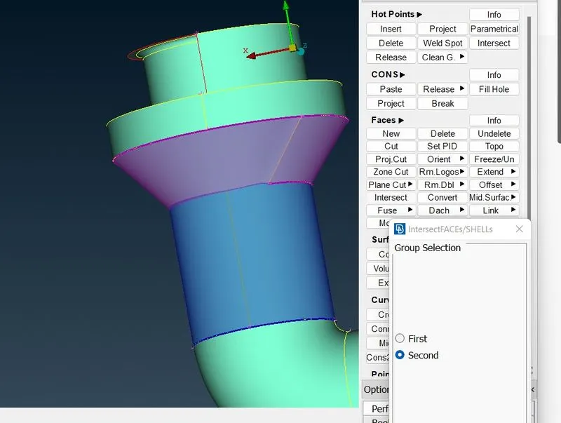
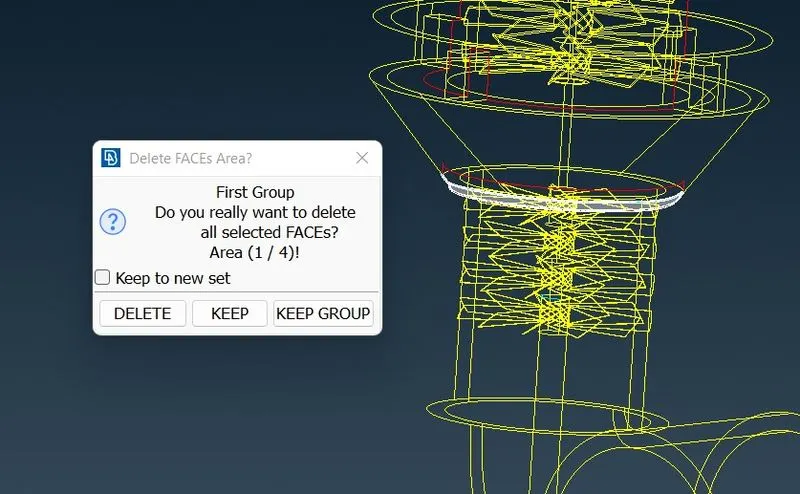
then we have removed all the unwanted surface andmake it clear.
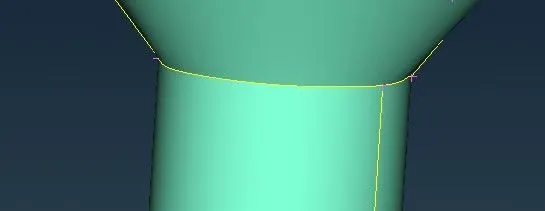
the yellow cons are made after intersection now we erase some line and make the shape perfect.
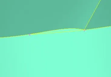
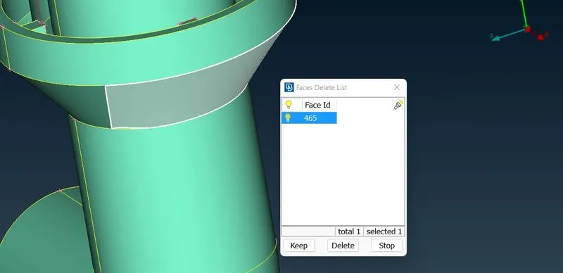
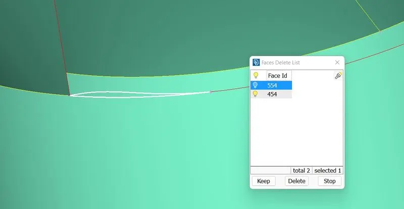
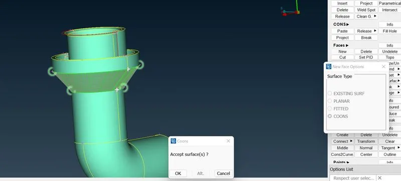
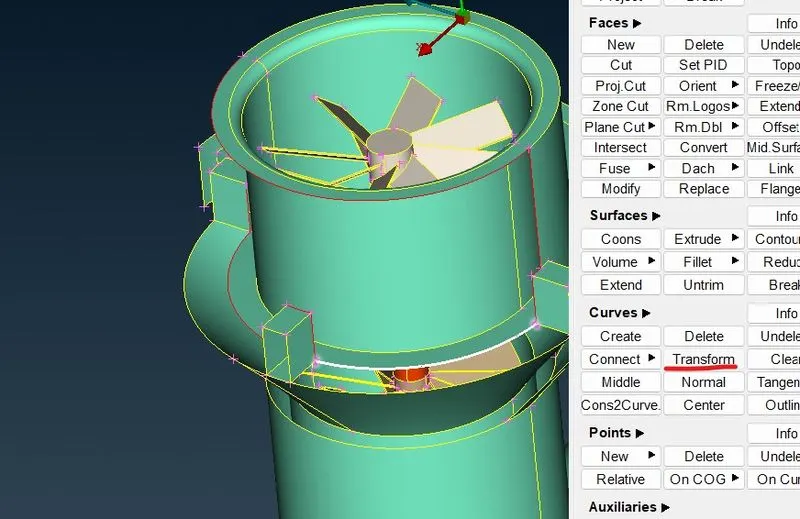
we have red cons on the top of the comopresser chamber we are using transform option to draw a same curvy imaginary line above the point.
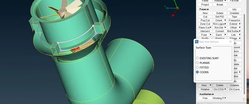
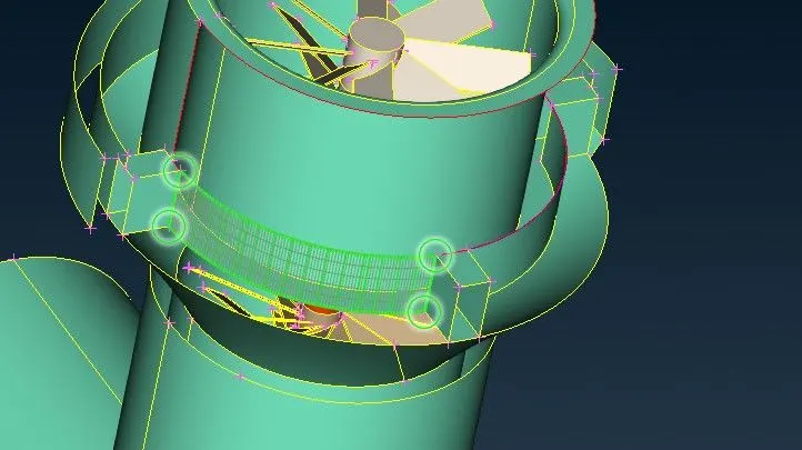
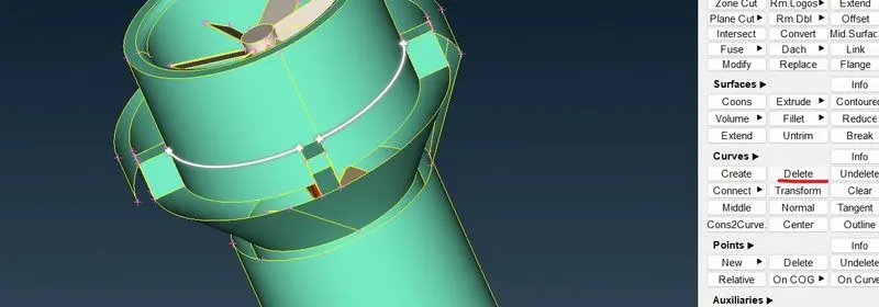
after finishing the geometric clean up check for errors.
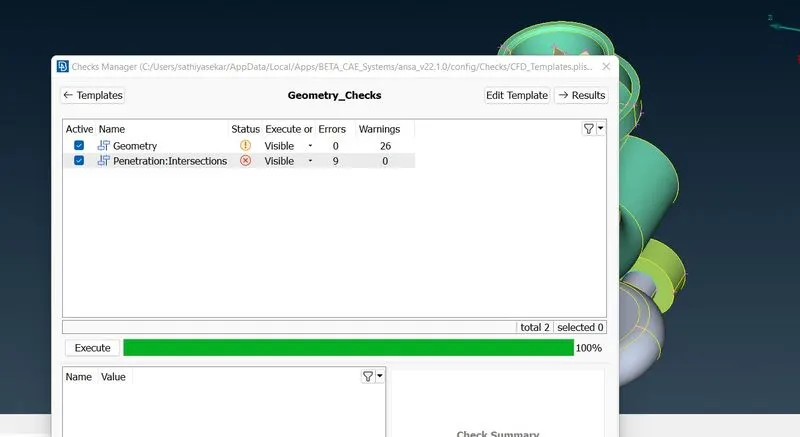
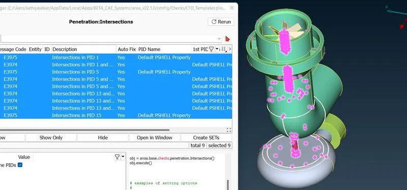
we found lot of intersection errors. lets clear all the intersection error before surface meshing.
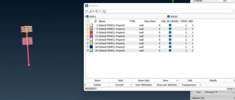
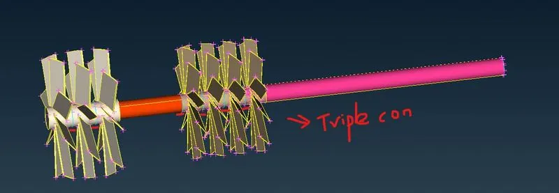
we have to remove the excess surface from the blades and the rotor shaft.
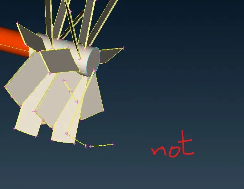
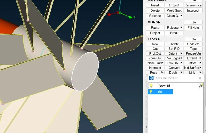
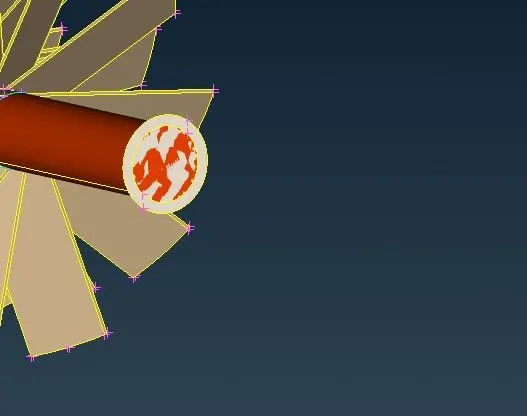
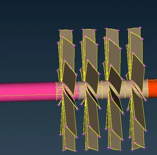
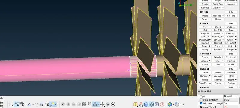
we are projecting the shaft and blade end so we cut the excess part from the profile.
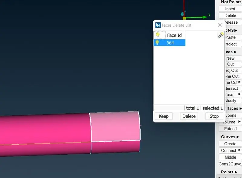
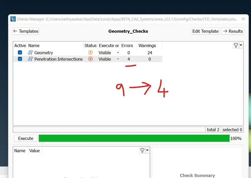
now we are again doing geometric check and we have solved 5 intersection on theblade and shafts rotor.
now we gonna clear intersection error in between the shaft and compressor chamber.
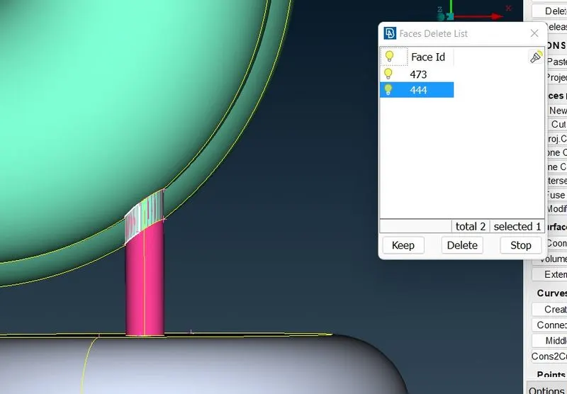
we delete the excess surface.
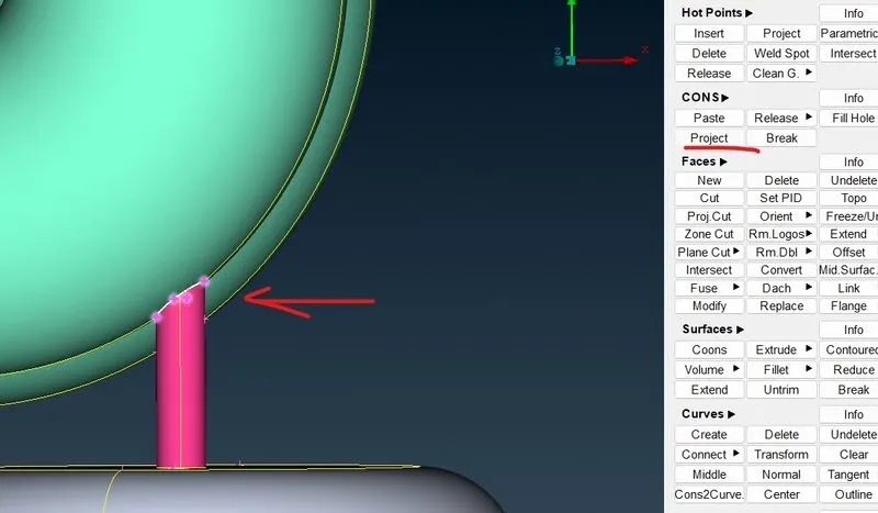
now we project and cut the excess surface inside the compressor chamber.
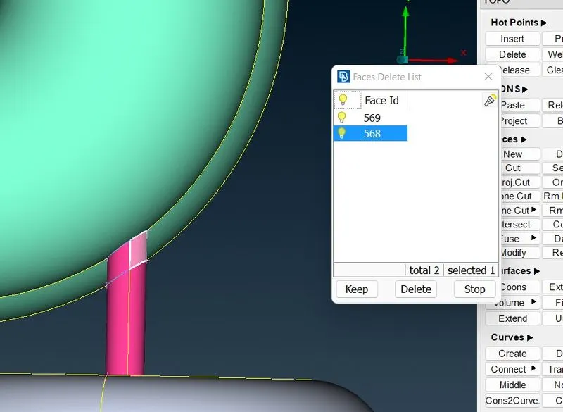
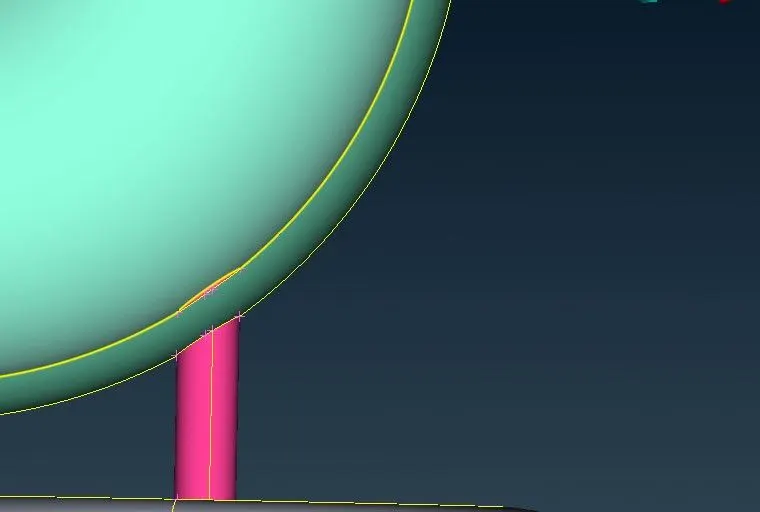
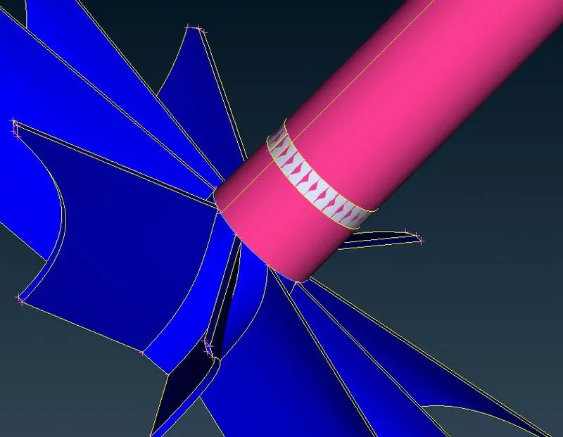
now removing glitch inside the turbo chamber.
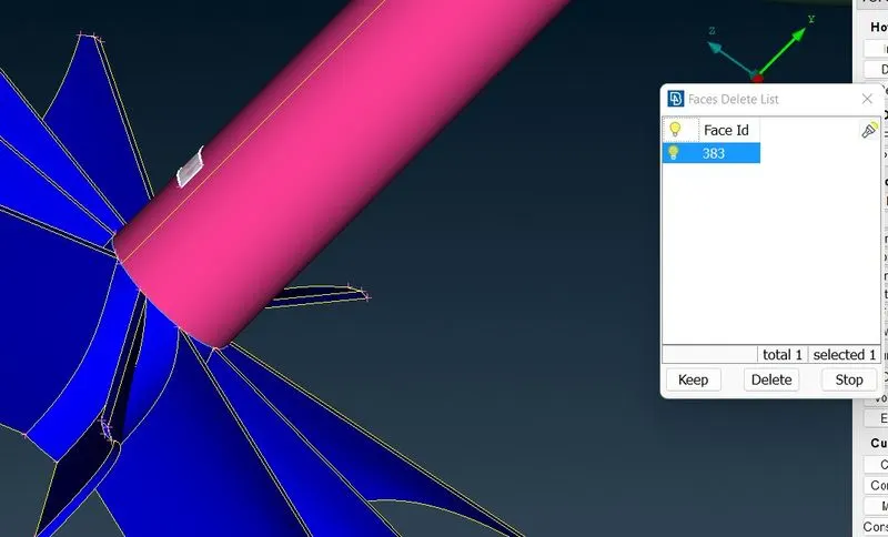
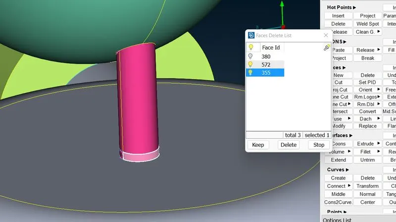
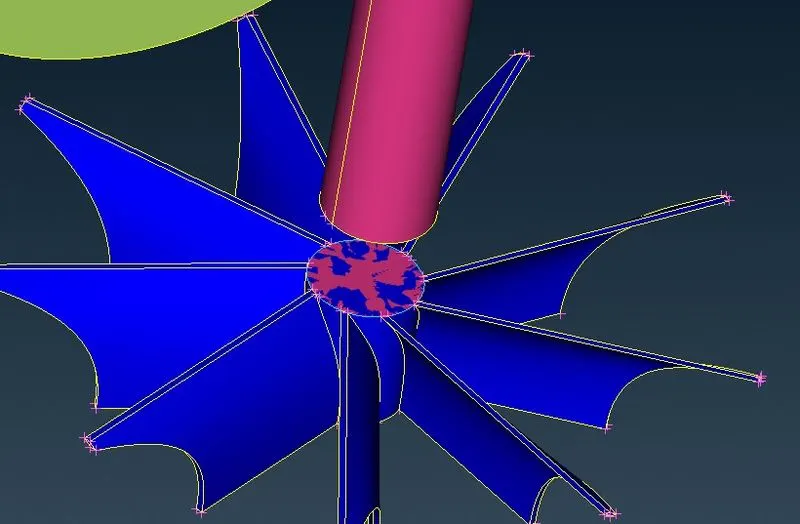
excess surface is removed.
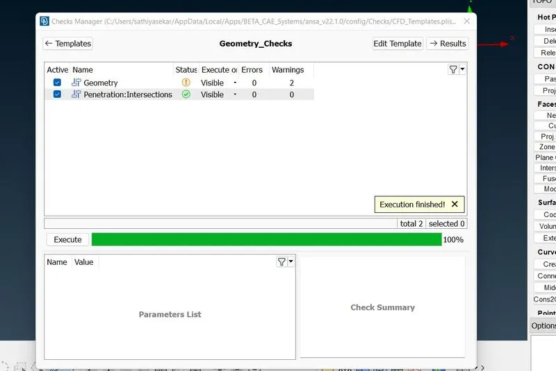
all geometric errors and intersection errors are removed now before going to meshing we have to close the open surface after asigning pid for the parts.
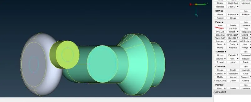
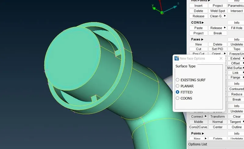
using fitted in new face we have to close all the holes which is shown above.
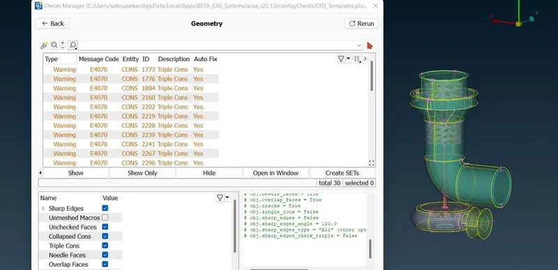
now we have checked for geometric check we got only warning, so we gonna start doing surface meshing for the targert length which is given for us.
turbo casing, inlet casing cover and compressor casing the target length is 5 mm so we gonna apply for all and we gonna do spotmesh.
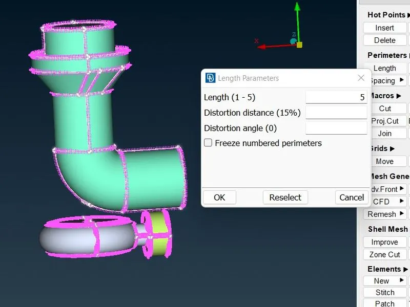
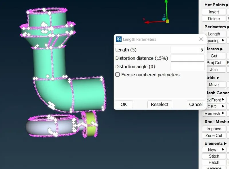
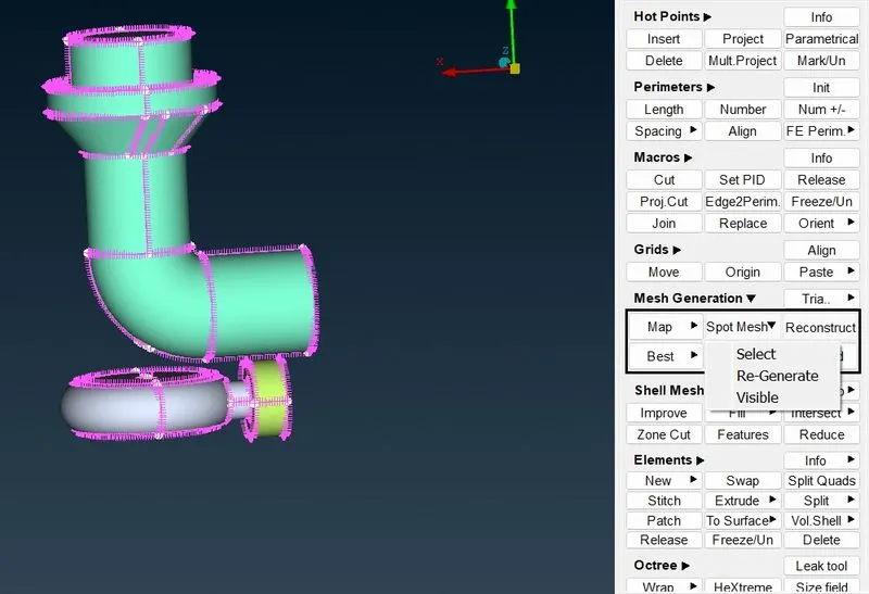
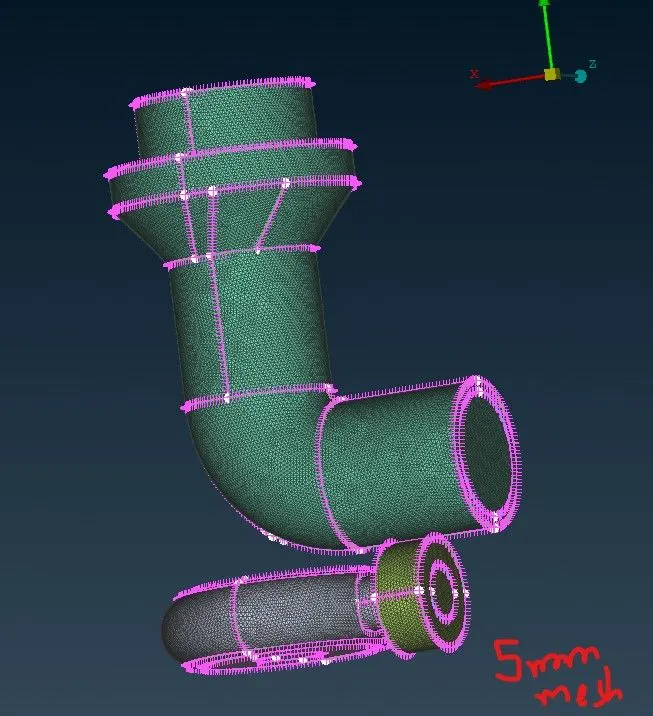
now we gonna mesh the blade 1 and blade stage 2 and shaft for 1 mm.
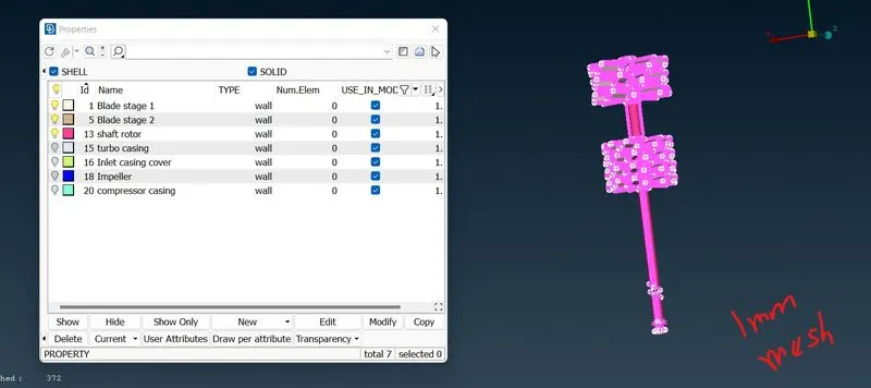
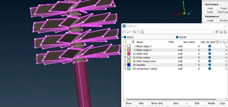
now we are meshing the impeller for 2 mm.
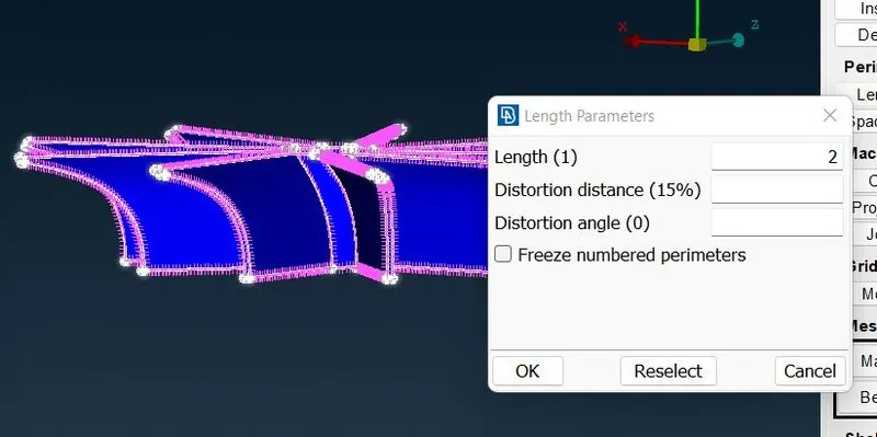
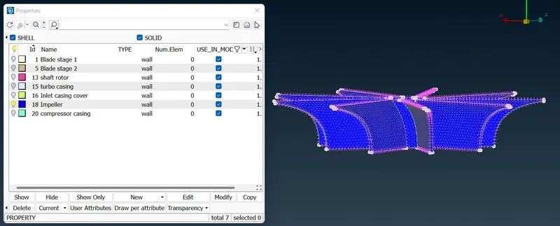
after viewing all the pids we get to know we have not meshed some of the parts which is due to perimeter difference so we have to mesh the unmeshed part using free mesh visible. so it adapts to the perimeter automatically.
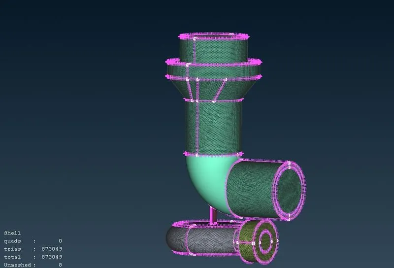
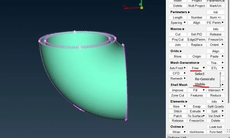
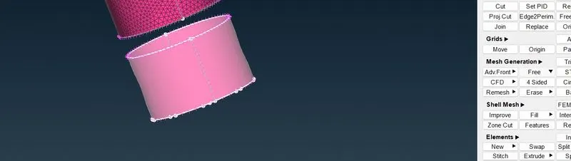
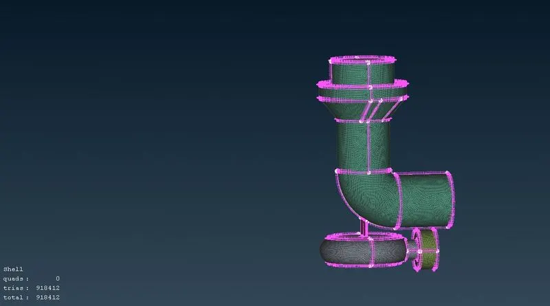
now everything has been meshed.
now we can proceed for volumetric mesh.
volume mesh
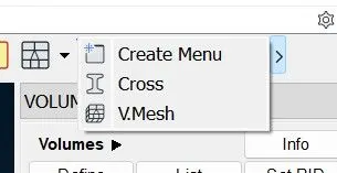
we have to define the geometry after entering into volume mesh.
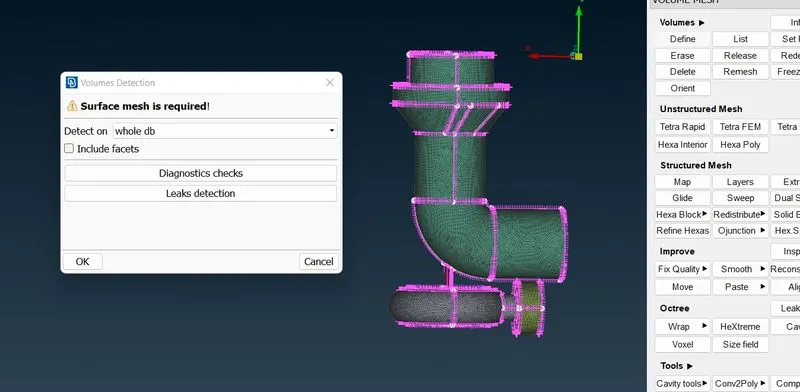
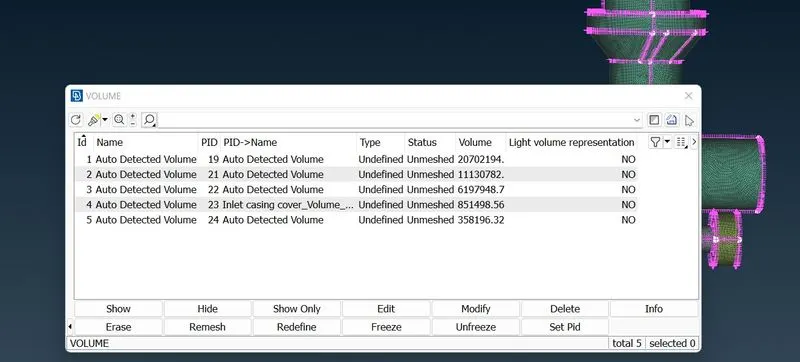
we will get automatic detected volume so we have mesh the internal volume and we have to delete the external detected volume.
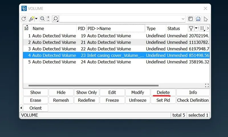
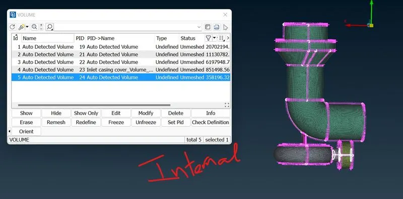
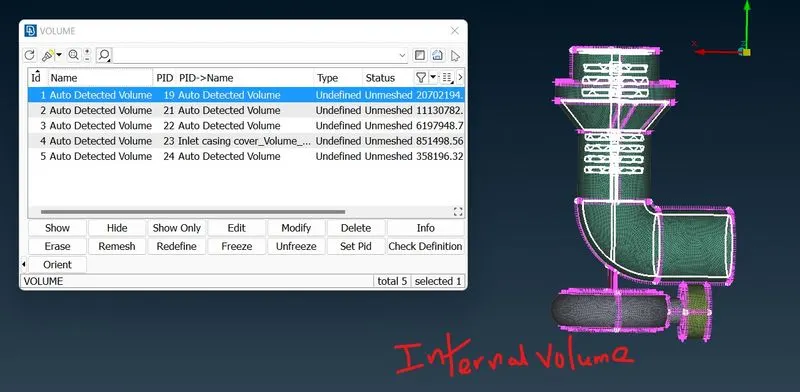
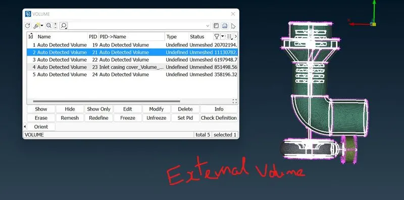
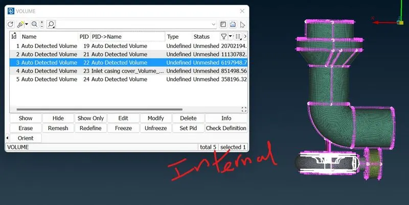
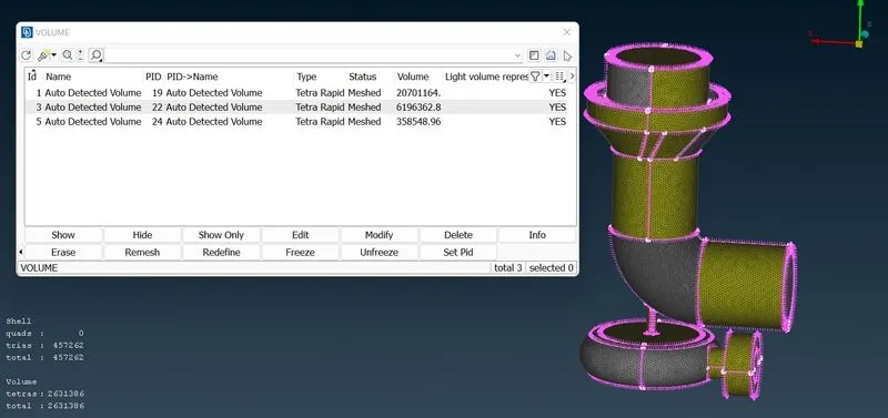
we have meshed the internal volume using tetra raped mes. so all the internal volume is meshed and im gonna show the cross view of the turbo charger.
Result.
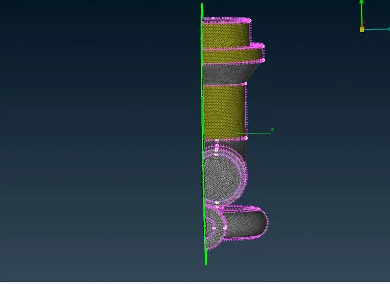
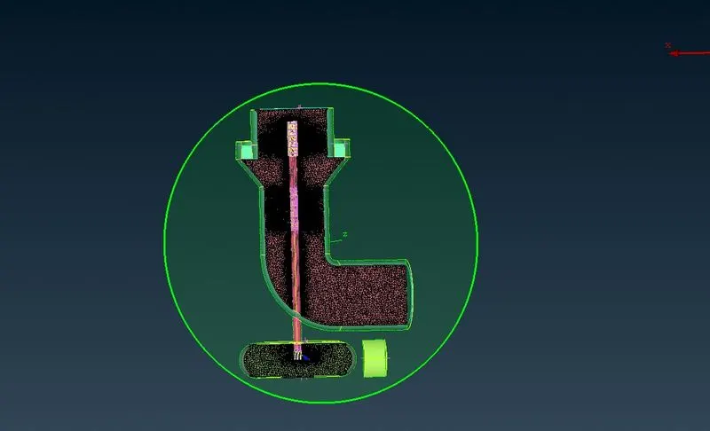
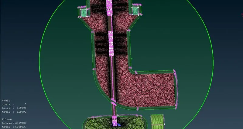
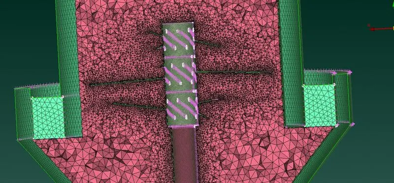
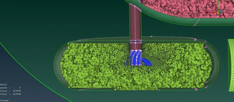
volume mesh has been completly done. as per the request.
conclusion
we have now came to know the process for making the volume mesh. we have learned how to clean geometric error and intersection error and how to do surfacing meshing using different mesh and finally we finished the volume mesh.
https://drive.google.com/file/d/1GCaqifnQTR0arCpEhHyP9mhSv16NUXqk/view?usp=sharing