Week 3 Challenge
AIM:
To fix the span length as per IRC 5 guidelines and also how to control the uplift pressure.
1.How hydrology and geotechnical studies (preliminary and detail studies, zone of influence) are used in fixing span as per IRC standards and type of bridge. Mention the clauses applicable for the same.
Determine the scour depth at the pier and abutment location having silt factor =3
Design discharge = 1000 cumecs
Linear waterway = 128 m
1b. what measures can be taken to avoid scour at bridge for shallow foundation. Also draw the section of measures on the downstream and the upstream side.
(Note: Draw all the drawings to the scale and neatly)
1.c What is uplift and how it can affect the foundation. (loss of contact)
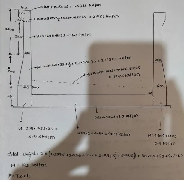
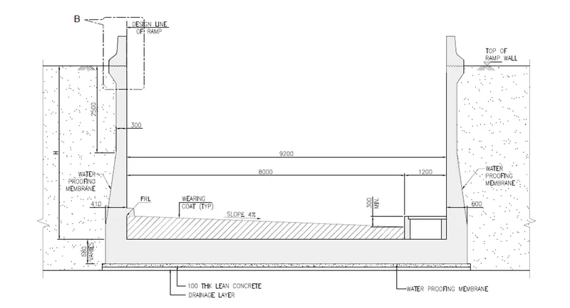
Calculate the uplift in U trough of below section with height 3,4,5 meters. with water level on top of ramp wall level .
What are different measures that can be taken to avoid uplift.
1.How hydrology and geotechnical studies (preliminary and detail studies, zone of influence) are used in fixing span as per IRC
standards and type of bridge. Mention the clauses applicable for the same.
Determine the scour depth at the pier and abutment location having silt factor =3
Design discharge = 1000 cumecs
Linear waterway = 128 m
Fowing are the ways by which the span length fixed according to IRC 5:
Planning Strategies
Integration with Road Network
The first step in the planning of a bridge project is to ascertain its location in the link of the roaad network and function thereof. The bridge shall fit
into the road link in a seamless manner and contribute to its primry function. Most road links have both mobility and accessibility functions in
varying degrees, which shall be taken into account while planning.
Interaction with other Authorities and Public
It is necessary to interact with authorities and local public who are directly or indirectly connected with the project or whose works or authority will
be directly or indirectly affected.
Siting of a Bridge
River Bridge
a. A bridge should be ideally sited accros the narrowest width of the river or channel where the course of the channel is staight in considerable
length on both up-stream and down-stream sides of the site and the banks are stable having no history of being out-flaked.
b. The cardinal principles to br kept in view at the time of selection of a particular bridge site including river training works are to provide a
suitable crossing consistent with safety and economy and acceptable detour from the existing road alignment . The following shall be the guiding
considerations in the regard:
1. Bridges up to length of 60 metres- The location shall be governed by suitability of alignment of road, unless there are special problems at
the crossing with regard to design and maintainance of the bridge.
2. For bridges having a length between 60m and 300 m- Suitability of site of the bridge as well as that of the alignment of approaches shall
be considered together.
3. For bridges having a length more than 300 m- The requirement of a good site fot the bridge shall have the precedence and the alignment
of approaches will have to conform to the selected bridge site.
DESIGN CONSIDERATIONS
STANDARD OF ROAD The district level roads MDR , ODR and VR may have submersible bridges though some MDR and ODR depending on its
strategic importance fit for high level bridges.
GEOGRAPHY OF THE AREA If the geography is such that a vast area is affected by the spraed of floodwater submersible bridge would be
prudent choice because planning for high level bridge under such circumstances will require very long approaches, which will create obstruction to
flow.
Heading up of water on upstraem of the bridge (afflux) due to embankments and obstruction to flow of water need be considered while planning
for this type of bridge since such obstruction is responsible for increased exit velocity and the scour on downstraem of the bridge.
VERTICAL GEOMETRY OF THE ROAD Vertical geometry of the road many times dictate the road top level of the bridge, which results into
selection of a type of bridge i.e., high level or submersible e.g. the nallah/river passing through habited area and it is not possible to go for
approaches in banking or even to cut. Such situations necessarily warrant selection od submersible bridges.
Determine the scour depth at the pier and abutment location having silt factor =3
Design discharge = 1000 cumecs
Linear waterway = 128 m
Ans. Db=Design Discharge/Effective linear waterway=1000/128=7.8125 cumec/m
Mean Scour depth(dsm)=1.34*(Db^2/Ksf)^0.33=1.34*(7.8125^2/3)^0.33
=3.62m
Flood without seismic condition
1) For piers
Scour Depth=2*Mean
=2*3.62
=7.2m
2) For Abutment
Scour depth=2*Mean(With Scour all arount)
=2*3.62
=7.2m
Scour depth=1.27*Mean(With approach retained or lowest bed level Whichever is deeper)
=1.27*3.62
=4.5974m
Flood with Seismic condition
For piers ------Scour Depth=0.9*7.2=6.48m
For Abutment ------- Scour Depth =0.9*7.2=6.48(with scour all around)
Scour Depth =0.9*4.59=4.13766m(with approach retained Bed level whichever is deeper)
Ques:what measures can be taken to avoid scour at bridge for shallow foundation. Also draw the section of measures on the downstream and the upstream side.
Ans: Contermeasures and preservation
Scour countermeasures are based on the type of scours such as contraction and local scour aggradation or degradation. The design and selection
of scour countermeasures depends on the type of scour problem at a specific bridge site can be classified to meet the following objectives:
Make existing bridge safe against scour.
To identify common scour problems at bridge locations.
To group together a family of site conditions causing scour.
To recognise modes common traits and physical characteristics causing scour.
To perform qualitative appraisals of the variety of scour problems at bridge sites.
To find suitable solutions for the scour problems.
To rate the bridges fo the degree and magnitude of scour.
The effectiveness of the countermeasure depends on the type of scour. When the magnitude of total scour is based on several types of scour acting simultaneously , the countermeasure shall be selected based on the governing and pre dominent component of scour.
Countermeasures.
Development of bridge inspection and scour monitoring programs: closing bridges when necessary
Providing riprap at piers and monitoring.
Providing riprap at abutments and monitoring.
Constructing guide banks(spurs/dikes)
Conmstructing river training countermeasures and channel improvements
Strengthening the bridge foundations
Constructing sills or drop structures(check dams)
Constructing relief bridges or lengthening existing bridges
| Scour Type | Countermeasures | Examples | Purpose |
| Lateral Erosion |
Armoring devices (revetment) |
Riprap gabions, cable ted blocks, tetrapods precast concrete blocks, used tre, etc. Vegetation planting | Prevention of erosion to the channel bank in the vicinity of the bridge: stabilization of the channel alignment. |
| Retardation | Timber piles, sheet piles Jack or tetrahedron fields planting Vegetation | Reduction of flow velocity near channel bank and inducement of deposition of sediment stabilization channel | |
| Groynes Hardpoints | Groynes, spurs, dykes |
Reduction of flow velocity near channel bank and inducement of deposition of sediment stabilization channel alignment |
|
| Degradation | Check dams | Control of channel grade | |
| Channel lining | Concrete or bituminous concrete pavement | Control of channel degradation | |
| Bridge modification | Increase of bridge opening width | ||
| Aggradation | Channel improvement | Dredging clearing of channel Formation of a cut-off | increased sediment transport to reduce sediment deposition at bridge crossing |
| Controlled mining | Reducing in sediment input at bridge site | Reduced local scour | |
| Debris basin | Reduction in sediment input at bridge site | ||
| Local sour | Armoring devices | Riprap, gabions, cable bed blocks, etc. | Reduced local scour |
| Flow attering devices | Sacrificial ples. deflector vanes, collars | Reduced local scour at piers | |
| Underpinning of bridge piers | Reduced local scour at piers | ||
| Guide banks | Improved flow alignment at bridge crossing: reduction in local |
Rigeap, though a widely used scour countermeasures, has limited applications in conditions marked by very high flow velocity and high intensities of bed-sediment movement. Additionally in situations where a pier is in close proximity to an abutment, placement of a scour countermeasures may need to take the pier proximity into account. In other situations suitably large riprap may not be readily available.
Although riprap has been widely used, following countermeasures may be used as alternatives to rigrap
hydrostatic pressure applied over the entire area. The hydrostatic load shall be measured from the underside of construction.
The structure must be designed properly to provide greater resistance against uplift forces in order to prevent risks due to water pressure. So, the uplift pressure must be taken into consideration during design stage since rehabilitation and maintenance of foundation cannot be carried out easily in the future.
The possibility of occurrence of this upward force on foundation should be check when groundwater table is higher than the bottom of the foundation level. Due to the fact that hydraulic uplift pressure acts in upward direction. Therefore, it reduces the downward weight of the structure and consequently it acts against the stability of structure.
a Gabions and Reno mattresses
b. Grout filled bags and mats
e. Cable tied blocks
d. Tetrapods. dolos and related units
e High density riprap
f. Grade control structures
g. Grouted concrete, pavement and flexible bed armour
2. Flow altering countermeasures (with relatively few field applications)
a. Sacrificial piles
b. Upstream sheet piles
e. Collars and horizontal plates
4. Flow deflecting vanes or plates
e. Modified pier shape or texture
f. Slots in piers
g. Suction applied to bridge piers
Note: Flow altering countermeasures should only be used in combination with primary countermeasures such as riprap to improve their effectiveness.
How to Check for Uplift Pressure?
The weight of the substructure should be greater than uplift pressure in order to meet the requirements of applicable codes, ie, sunation of
downwand load per given ares should be larger than that of the vertical load per given area.
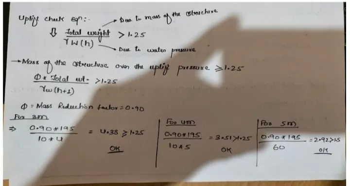
The downward load should at least greater than 25% compared to the upward load due to bydrostatic load. The following expression can be
used to check the occurrence of uplift force below the structure under considerations
OW/w(h+1)≥1.25 Equation 1
Where:
O :mass reduction factor, can be taken as 0.50
W: the mass of the structure
w:specific weight of water
h: height of water from the water table to the bottom of the foundation
1. Factor of safety
What is uplift and how it can affect the foundation. (Loss of contact)
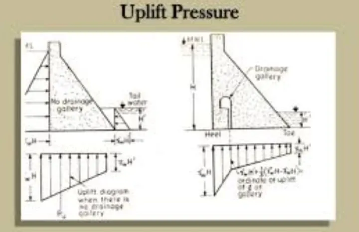
Uplift pressure, which is also known as hydrostatic uplift, is an upward pressure applied to a structure that has the potential to raise it relative to its surroundings. It is the condition of greater pore water pressure than the overburden pressure of the structure.
The uplift pressure can be problematic if it is greater than the weight of the structure exerted downwards. ASCE 7-10, states that the upward pressure of water shall be taken as the full
Consequences of Uplift Pressure
1. It reduces the effective weight of the structure.
2. Endanger stability of the structure
Strategies for Prevention of Uplift Pressure:
Dewatering procedure may help to control the water away from construction site, but it cannot keep the dewatering the whole life span of the construction as it is not an economical move. There are number of methods by which the influence of uplift pressure is avoided.
1. Toeing in the foundation into the surrounding Ground
When a substructure is built inside an open excavation or temporary cofferdam.
the base slabor raft foundation can be extended outside perimeter to increase resistance to uplift. The weight of backfill material on the tied-in
foundation increase the weight of the structure against uplift pressure. This method is not feasible where a diaphragm or secant pile wall is
used as a permanent retaining structure.
2 Increase the sallalt of the structure
The self-weight of the building can be increased by increasing the size of structural members. sometime, the dead weight of the low-rise
podium in a high-rise complex is increased by incorporating a rooftop garden with a thick soil fill.
3.Ground Anchor:
Pre-stressed anchors can be used as a temporary measure to counteract uplift forces. Permanent application of ground anchors is limited by
concems about their long-term performance with respect to corrosion
4. Piling metod
The piling method is the most effective method to resist Uphift pressure.
Various types of piles are available to be used for countering uplift pressure based on soil condition and their necessity on site. For instance,
end bearing pile, friction pile, un reamed pile, sheet pile, tension pile, and compaction pile. Table 1 presents different types of piles used to
contain uplift pressure based on soil conditions
Types of Piles Chosen Based on Soil Conditions to withstand Uplift Pressure:
Unreamed pile :It is used in black cotton sods, filled up ground and other types of soils having poor bearing capacity.
Sheet pile:Sheet piles, which made of this plates of concrete, timber, or steel driven into the ground for separating members or stopping
seepage of water, it is not constructed for carrying any vertical load.
Tension pile:Tension piles uplift piles anchor down the structures subjected to uplift pressure.
Compaction pile:It is driven in loose granular soil.