Week 3 Challenge
CAR TAIL LIGHT LENS:
A car headlamp lens is a protective covering that is mounted on the front of a car's headlamp assembly. The lens serves as a protective barrier against any debris, dust, or elements that could damage the headlight bulb. It is typically made of high-quality plastic material that is transparent and scratch-resistant. The lens also helps to focus the beam of light emitted by the headlight, improving visibility for the driver in low-light conditions. Over time, the lens can become dirty or cloudy from exposure to the sun and other environmental factors, reducing the amount of light that passes through it. In such cases, the lens may need to be cleaned or replaced to restore its clarity and effectiveness.
A car tail light lens is a component of a car's rear lighting system that covers the light bulbs and protects them from the elements. It also helps to enhance the visibility of the car's rear lights, making it easier for other drivers on the road to see the vehicle from a distance.
The lens is typically made of durable materials like polycarbonate or acrylic, which are resistant to shattering and UV radiation. It may also feature specific colors or patterns to indicate different functions, such as red for brake lights, amber for turn signals, and white for reverse lights.
In recent years, there has been a growing trend towards using LED lights in car tail light systems, which offer several benefits over traditional incandescent bulbs. LED lights are more energy-efficient, longer-lasting, and provide a brighter, more intense light output. As a result, many modern car tail light lenses are designed to accommodate LED bulbs.
DIFFERENT TYPES OF CAR TAILLIGHT LENS-
There are several types of car tail light lenses, each designed for specific functions or purposes. Here are some of the most common types:
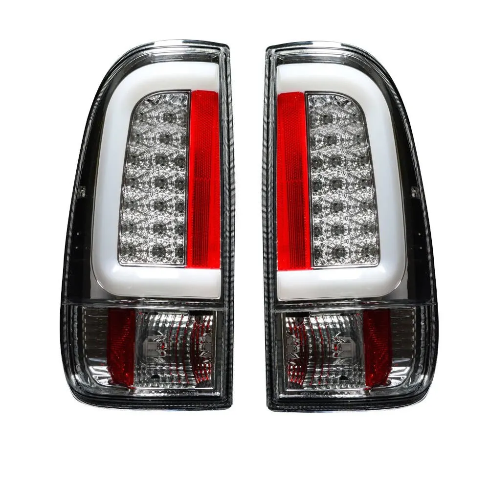
Clear lens: A clear lens is a standard type of tail light lens that allows the full brightness of the light to shine through. These are commonly used for reverse lights or as additional lighting.
Red lens: A red lens is used for tail lights, brake lights, and turn signals. This color helps to differentiate the rear lights from other lights on the car and indicates when the driver is braking or turning.
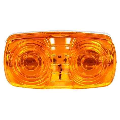
Amber lens: An amber lens is used for turn signals or hazard lights. The bright color helps to catch the attention of other drivers and signal the driver's intentions.
Smoked lens: A smoked lens has a dark, almost black appearance, which gives the car a more aggressive look. These are often used on sports cars or customized vehicles.
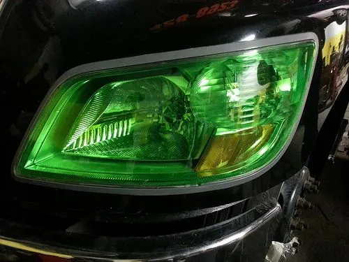
Colored lens: Colored lenses can be used to create a unique look or match the color scheme of the car. However, it's important to check local regulations to ensure the colors used are legal.
LED lens: LED lenses are designed specifically for LED bulbs, providing better light output and energy efficiency compared to traditional incandescent bulbs.
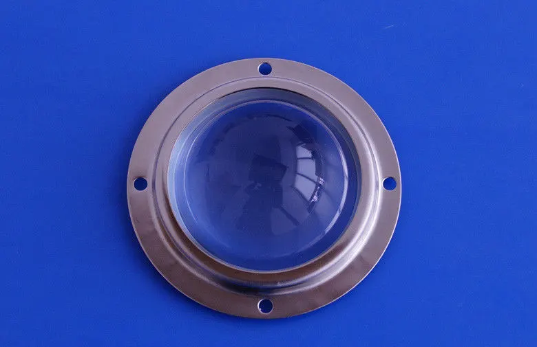
Custom lens: Custom lenses can be designed to fit specific vehicles or to create a unique look. These are often used for customized or modified cars.
Objectives:
- Creation of Tooling Axis.
- Creation of Class B and Class C surface.
- Creating a solid part out of surface modelling.
- Draft Analysis of Class A surface and final plastic component.
Tool Used: CATIA V5
Introduction: In this project we are designing a tail light lens using given class A surface. The approach includes creation of Class B surface keeping 2.5 mm thickness in mind for the complete component. The design also included Class C creation from the given parent surface.
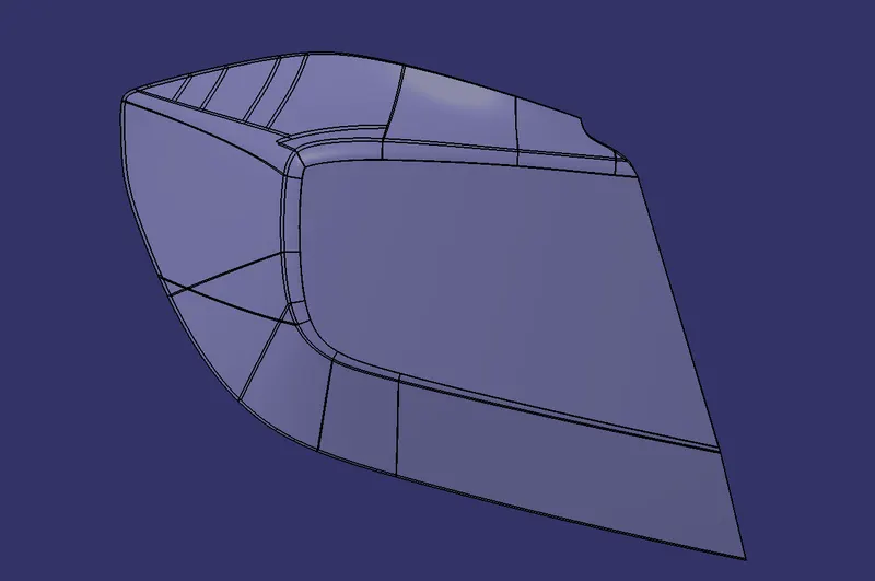
CLASS A: Following surface is given as the input for the component creation.
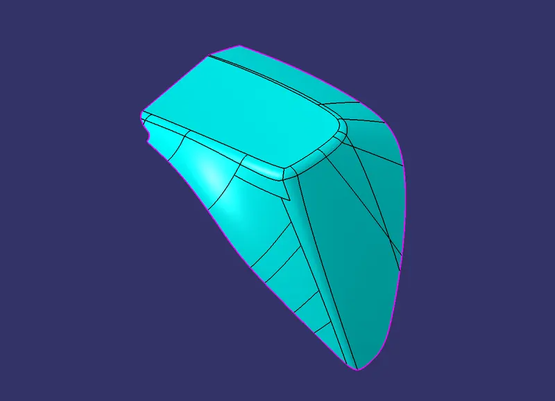
To continue with the design process first we need to find out the tooling axis for the surface and check for all the drafts using Draft Analysis tool of CATIA.
Draft Analysis for Surface A:
The analysis is done for 3degree draft. So as can be seen all the surfaces are than 3deg.
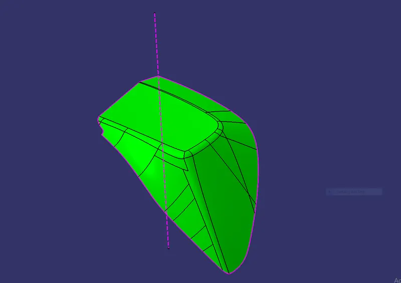
Creating of Tooling Axis:
- Create an intersection of CLASS A surface with ZX plane and from the intersection create the tooling axis as shown below.
-
Creation of Class B:
- Now for Class B creation, we have extracted surface from Class A and untrimmed them to obtain the original parent surface.
- These surfaces are then offset to the required thickness.
- After offsetting, all the surfaces are trimmed into the required shape.
- Required fillets are given to the surfaces.
Creation of Class C:
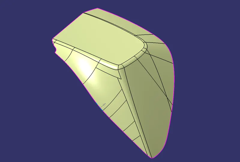
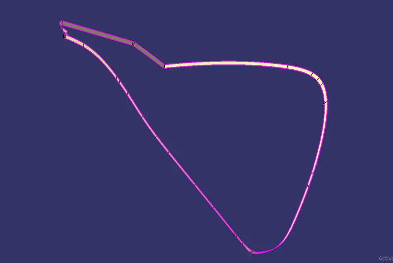
- For creating this surface we have extracted the boundry of Class A using multi-extract and then converted to smooth curve.
- Now this smooth curve is swept along the draft direction with a 3deg draft.
Final Trims:
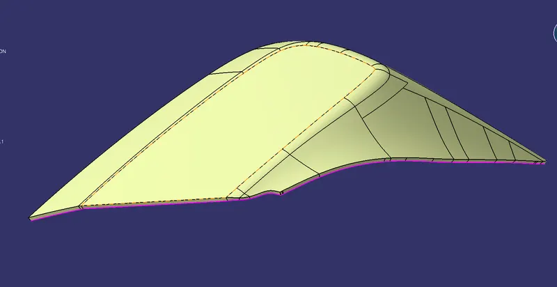
Class A + Class C:
To make sure that there is not any open boundry between class A and class C, we have used join option to created the single body. This is done to make sure that the parting line doesn't lie between the these two surfaces.
Class A + Class B + Class C:
For this we have trimmed the above shown surface with the Class B surface using trim feature.
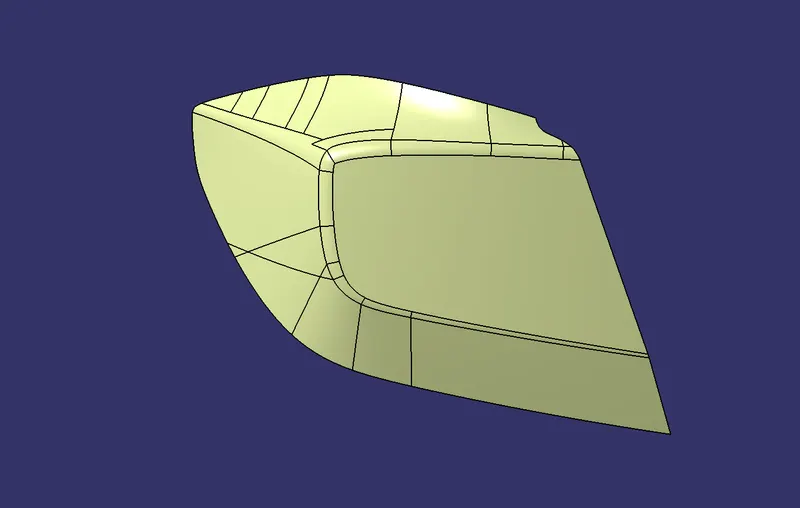
All the main features are published as can be seen in the image shown above.
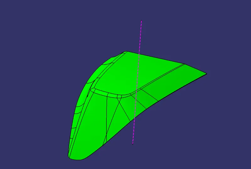
Draft Analysis on the Final Component:
For this analysis, main tooling axis is taken draft reference.
Following results were obtained:
TRANSPERENT VIEW OF TAIL LIGHT LENS