Week 3 Challenge
Ans 1 Primary Load Cases includes:

ANS 2: One-Way Slab:
Slab characteristics are defined by the load transfer phenomenon to its support i.e. whether they are distributing its load in one direction or both direction.
If Slab is giving its load predominantly along one direction only, then it is said to be One-Way Slab.
Slab Characteristics are defined by its support condition along the periphery. If Slab is constrained along all the direction with the same type of support, then Lx/Ly ratio >=2 give One way slab load transfer phenomenon.
-----------------------------------------------------------------------------------------------------------------------------------------------------------------
ANS 3
Unit Weight of structural steel & soil are:

Soil unit weight : 19.2 KN/m3 (18-20 KN/m3)
-------------------------------------------------------------------------------------------------------------------------------------------------------------------
ANS 4:
Sections that can be defined using properties tab in staad pro includes:
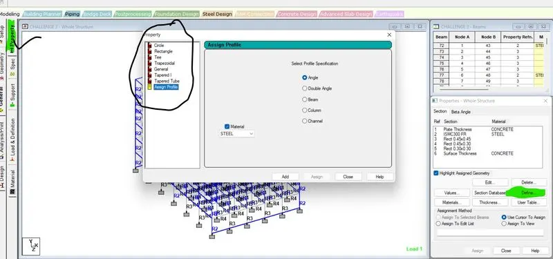
- Circle
- Rectangle
- Tee
- Trapezoidal
- General
- Tapered I
- Tapered Tube
- Assign Profile (Angle, Double Angle, Beam, column, channel)
-------------------------------------------------------------------------------------------------------------------------------------------------------------------
ANS 5:
Primary Beams:
Load Transfer process in frame structure follow such process:
SLAB < BEAM < COLUMN < FOOTING < SOIL
Beams which directly tranfser its load to the next supporting element i.e. column are called primary beams.
or we can say that Primary Beams span along two colmns connected with footing at its base.
--------------------------------------------------------------------------------------------------------------------------------------------------------------------
ANS 2 (1). Factors & parameter influence the design pressure intensity of a high-rise building:
- Risk Coefficient factor (k1) (depends on importance of structure & return period opted by the design team).
- Topography & Terrain Condition (k2) : Buildings are characterised into four categories based on its local conjestion around the neighbourhood of that particular structure as defined in IS 875: PART 3 on page no. 7-8.(6.2.1 to 6.2.4)
- Topography factor whose value lies in between (1-1.36) for windward slope>3. (Annex C of is 875 part 3)
- Importance Factor for cyclonic region (applicable for coastal region within a belt of 60 km from the sea and type of commercial structure).
-------------------------------------------------------------------------------------------------------------------------------------------------------------------
ANS 2 (2):
Load Transfer process in a reinforced concrete building follow as such :
1. Slab(Act as Membrane element)
2. Beam (Primary & Secondary beam)
- Primary Beam: transfer the load coming over its span directly to its supporting element whose failure result into complete collapse of the structure.
- Secondary Beam : Such Beam connect along two primary beams or between one primary beam and column. such Beams reduce the deflection along the span along with Support reaction and Longitudinal & transverse moment over main column.
3. Braces : Lateral restrained element provided to minimise sway displacement across the plan of its installment.
4. Column: Take load from the primary beam & transfer it to the footing.
5. FOOTING: Its a component who transfer the load coming over the structure to the supporting soil under it.
--------------------------------------------------------------------------------------------------------------------------------------------------------------------
ANS 3 (1):
| One-WAY SLAB | Two WAY SLAB |
| Load transfer predominantly along one direction only. | Load transfer along both of its supporting element. |
| Slab deflect along one direction i.e. act like a cylindrical shape | Slab deflect along both direction.(as a saucer) |
| Main R/F is provided along shorter span only. | Main R/F is provided along both of its span. |
| Aspect Ratio i.e. Lx/Ly>= 2 | LX/Ly<2 |
| no meshing is provided along the discontinuous corners. | Top & Bottam mesh r/f (0.75*Ast along shorter span) is provided at the discontinuous corners to prevent corner from lift. |
------------------------------------------------------------------------------------------------------------------------------------------------------------------
ANS 3 (2):Secondary Beams are provided either between two primary beams or between primary beam & column.
They reduce :
- Deflection of the slab
- Reduce Support reaction of the primary beam
- Reduce the logitudinal & transverse moment coming over the length on primary beam.
- Reduce the randomness of load action coming along the primary beam span.
- Increase the Lateral Siffness of the primary beam help from preventing local twisting along the length.
- enhance the overall stiffness of the building.
- Torsion resistance has been enhanced as well as torsion moment generation would be minimised to much extent.
-------------------------------------------------------------------------------------------------------------------------------------------------------------------
ANS 3 (3): Primary Load Cases:
| PRIMARY LOAD CASES | IS CODE | PARAMETER | DESCRIPTION |
| Dead load | is 875 part 1 | density of different material | |
| Live Load | IS 875 Part 2 | type of occupancy & structure | |
| Wind Load | IS 875 part 3 | Terrain Height & characteristics, windward/leeward side | |
| seismic factor | is 1893: 2002 | Importance of structure, zonal consideration, Response reduction factor, spectrum acceleration coefficient | |
----------------------------------------------------------------------------------------------------------------------------------------------------------------------
ANS 3 (4):
Steps involved in assigning properties & support to a model:
1. Both of above tabs come under the GENERAL task bar.
2. These assigning are done after modelling the structure.
3. Firstly" property" sub-tab under "GENERAL" tab is specified as per requirement, i.e. if the section is user-defined, then define the section from the various crosssection available under define tab such as circle, rectangle, Tee, Trapezoidal, Tapered I, Tapered Tube etc.
4. Then, specification is introduced to various elements as per designer will.
5. After specification is defined, supports are created followed by assigning to various nodes.
---------------------------------------------------------------------------------------------------------------------------------------------------------------------
ANS 3 (5):
TO create SECONDARY beam in staad pro, following steps to be followed:
1. firstly primary load members are created either by coordinate system or run structure wizard option.
2. After modelling the basic structure, use "insert mode option" in beam element to create the nodes of secondary beam.
3. we can also create the nodes of secondary beam using various tools like move, copy, mirror, paste, intersect beam option etc. as per requirement.
4. After modeling the secondary beam, its properties are to be specified under "specification" tab within GENERAL tab.
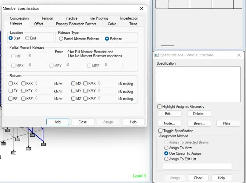
5. Select BEAM option from the popup menu in the right hand side of this screen.
6. Use various option as per requirement such as RELEASE is used to relieve the reaction either at start or at end.
7. These restraint at ends may be partial or fully restraint.
8. Offsets are used to connect BEAM- COLUMN Joint perfectly.
-------------------------------------------------------------------------------------------------------------------------------------------------------