Drafting of various geometries using Chamfer, Fillet tool in AutoCad
AIM: Create the Drawings mentioned in the attached folder using any of the coordinate system with neat & labelled Dimension.
INTRODUCTION: Some of the commands used to create the following sketches are as follows:-
LINE Command: It is widely used command use either through "L" command or From Draw Toolbar option.
Mirror command:- It is mostly used to create the symetric drawing having an axis of Mirror.
Pline command: It is used to draw various figures like Lines, spline curves, Blend curves with variable properties along with a single line option. It means this command is the combination of Line+Join command.
Fillet Command: This Command can be used in multiple ways such as Spline Curves, Stretch or trim command.
UCS Command: Before Proceeding for creating any sketch, we should set our origin as per the space requirement.
UN command; It is mandatory to set the units with precision requirement before going further.
W Command: It is required to create the address of any sketch with dwg extension to get it opened at some other location as per our requirement.(WRITE BLOCK)
B Command: It is almost same as W command with only difference is not having an address in Dwg extension.
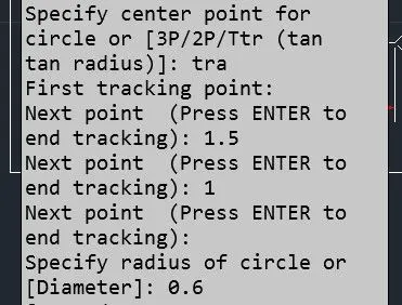
TRA Command: It is the boon to any draftman for creating any drawing without using unnecessary lines.THis command is used as nested within some other command like REC, Square, LINE, MOVE, ROTATE etc.
PROCEDURE:
FIGURE 1
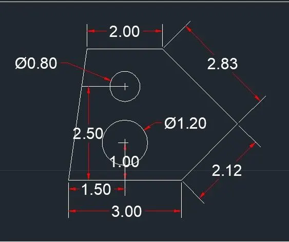
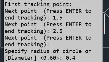
For describing its procedure,i have uploaded some screenshorts of code which are as follows :-
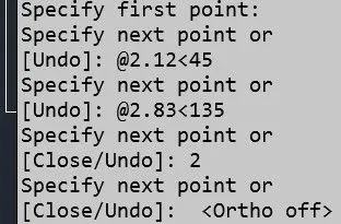
For Figure 2 ,description comes at below from here:
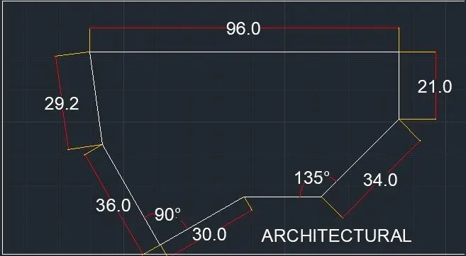
i have used some screenshorts to describe about the procedure of above figure :
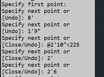
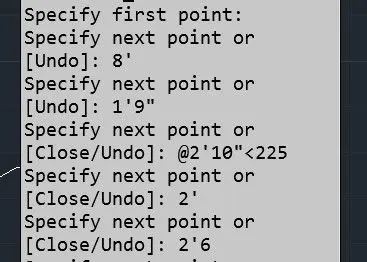
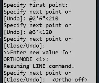
Here dimensions are written in inches instead of feet as it is by default recoomended by the Autocad version.
Figure3: here comes at below the procedure for drawing the sketch :
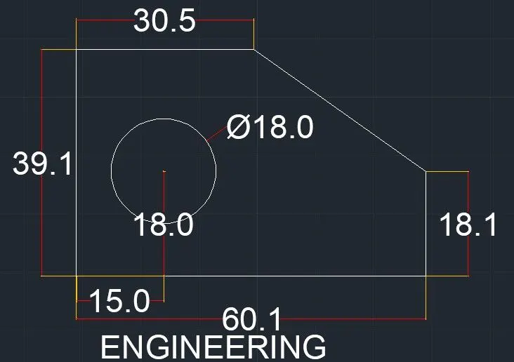
I have uploaded some screenshorts for elaborating the procedure as attached below:
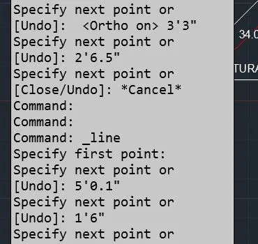
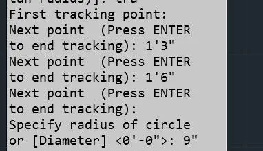
After Drawing the sketch as per the above attached code, it is required to Give the Dimensions with proper setting done through "ANNOTATE" Toolbar mentioned in Home tab.
Figure 4: Procedure of below figure is attahed through it through Screenshorts:
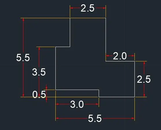
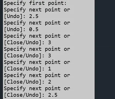
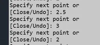
Here we have drawn the Drawing in metric system with Precision of 0 only having the Lighning system of "generic" mode.
FIGURE 5: here comes below the fig. 5 with the procedure attached in the form of workpad file:
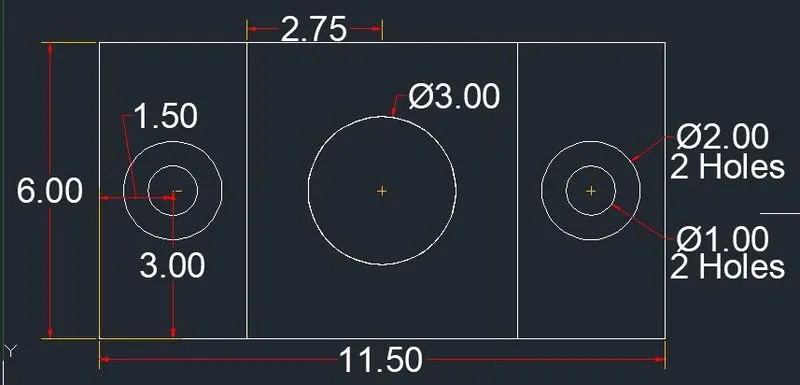
I have attached the procedure in the workpad form which can be seen through Browser tab mentioned at the bottam of page.
FIGURE 6: Given below the figure 6 with procedure attached in the form of Workpad:
Colour entitled to the alphabets enclosing within the boxes are matched with the colour of codal procedure attached below in the Browser:
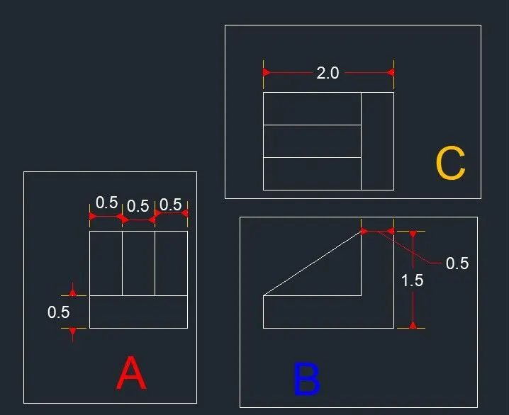
FIGURE 7: Given Below is the procedure of this mentioned drawing:
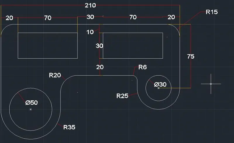
1. Starting sketching from top-left corner, use Line command to give a dimension of 20 units, followed by 70, 30,70 and lastly 20 units.
2. From last point, use line command to give dimension of 70 & 100 mm at right & left side of sketch respectively.
3. select "rec" command followed by tracking option of (20,10) on both sides of sketch.
4. after tracking that point, choose dimensions of that rectangle i.e. length=70, width=30 units.
5. on left bottam side, use track option within circle command to get the centre of 35 units.
same procedure is followed on right side followed by drawing concentric circle of radius as mentioned in that drawing.
After DRAWING THE concentric circle, use Arc command (start,end,radius) to get the required figure.
After fillet command, Erase the outer circle on both sides at bottam of the sketch.
6.Use fillet command with radius of 20 & 6 units on left & right side of this diagram respectively.
7. after Drawing, Assign the required properties using "ANNOTATE" Command.
FIGURE 8: Given Below the Figure 8 with the given procedure:

1. firstly, Draw a line segment having a dimension of 8.55 units.
2. on either side of this line, draw concentric circle of mentioned radius.
3. From the midpoint of this line, draw concentric circle of radius 2& 2.5 units.
4. using line command, draw a tangent connnecting outer circle of middle & outer side circle.
5. After Drawing both the tangent on same side, we may take a mirror image at centre of middle circle.
6.Erase the outer circle on either sides of the sketch and then use Arc (start, end, radius) to complete the figure.
Figure9: Here comes at below the Figure 9 with the mentioned procedure:
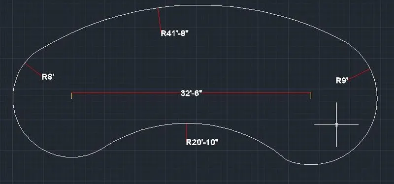
1. Draw the line segment of 32'6" dimension.
2. on Either side, Draw a circle of radius 8' & 9' on left & right side respectively.
3. Use fillet command with a radius filled with 41'8" joining both the circle at specific points.
4. Same procedure as above but with radius of 20'10".
After this, Erase the circle on either side and get filled with arc option (start, end, radius) on both sides with radius mentioned in the figure above.
Figure 10: Here Comes the FIGURE 10 with mentioned procedure to draw this sketch:
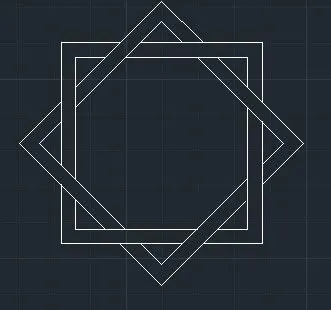
1. Firstly, use line command with dimension of 4' to draw a square.
2. then, use offset of 4" on inner side of this figure to get the smaller square.
3. Use Copy command to copy both the square and kept over the corresponding square.
4. Switching on Object mode, draw the Point made by intersecting the lines at the midpoint on all the sides .
5. Using This intersection as mentioned in point4, Rotate the copied square with 45 degree kept over the original figure.
6.After Using Rotate command, Use "BR" command to disjoin the point at two location followed by Erase command.'
7. Circulating the procedure mentioned in point 6, result into above mentioned sketch.
FIGURE: 11 HERE Comes the figure 11 with the procedure attached in the form of wordpad:
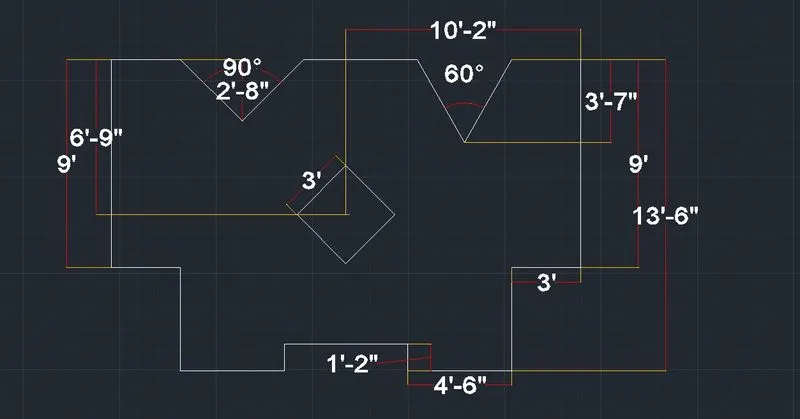
i have given the procedure in the workpad form attached below of this page with Nomenclature C-11.
RESULT:
Every Drawing is drawn to some scale so it is necessary to bifercate the drawing on the basis of scale in order to avoid any error related to scaling.
Write command(W) will help in solving the query of above problem.
Every time, its necessary to reassign the Origin with UCS Command before proceeding to next diagram with same scaling.
Check the Units (UN) Before drawing any sketch.