Creating a Floor plan, Footing detail and Isometric view using AutoCad
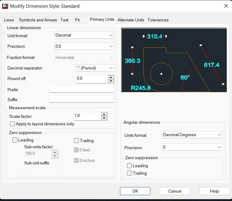
AIM: Create the Drawings given in the above mentioned challenge using any of the coordinate system with Appropriate dimensions as marked in the drawing along with modify the settings as per the requirement.
INTRODUCTION:
For creating the below attached drawings , we have used the various tools, commands etc. some of them are defined here as follows:
LINE: line command is used to draw the below drawings mainly.
Mirror: Mirror Command is available in the "MODIFY" Toolbar for creating mostly the symmetric drawing.
Fillet : this command can be used as a multifunctionality command as it joins the two lines as per our needs.
Break at two/one point: THis command is used to divide a line segment into different segments .
SCALE: it is used to magnify the text as per the drawing enclosed with it.
F5: it is used to draw the isometric drawing i.e. switcing on to different coordinate plane. FOR EXAMPLE: if we are working in the X-Y Plane,then using F5 key we can switch over to X-Z or Y-Z axis as per our needs.
OFFSET: it is used to draw the lines/ curve at a specified dimension & direction with original curve.
TRACE: this command is the boon of an autocad drawing as it eliminates a lot of miscellaneous work to be done in case of absence of this command.
PROCEDURE:
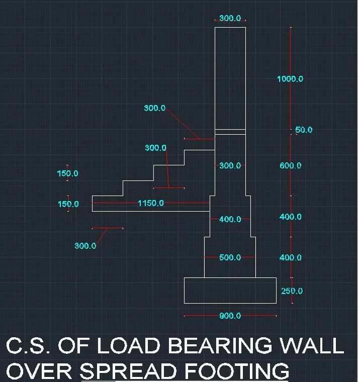
1. Firstly, define the units using UN command and fill the properties.(here all units are in mm and precision will be 0.0)
2. define the origin and then start plotting as per the demand.
3. Draw a rec. having dimension 900*250mm
4. Select LINE command and then Trace command to plot the coordinate above the mentioned rectangle.
5. REpeat the sequence of "line" and "trace" command to draw the sketch .
6. After drawing all the coordinate, use "dimlinear" command to measure & plot the geometry.
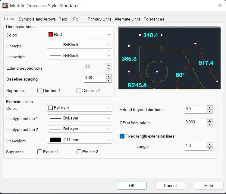
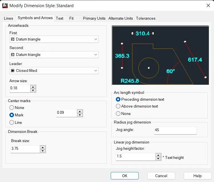
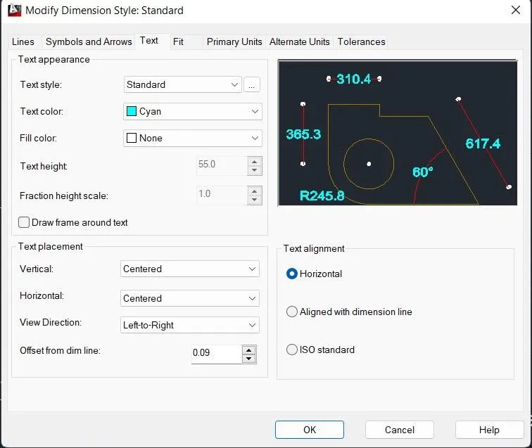
7. Check the properties of text, lines & arrows before proceeding for step 6.
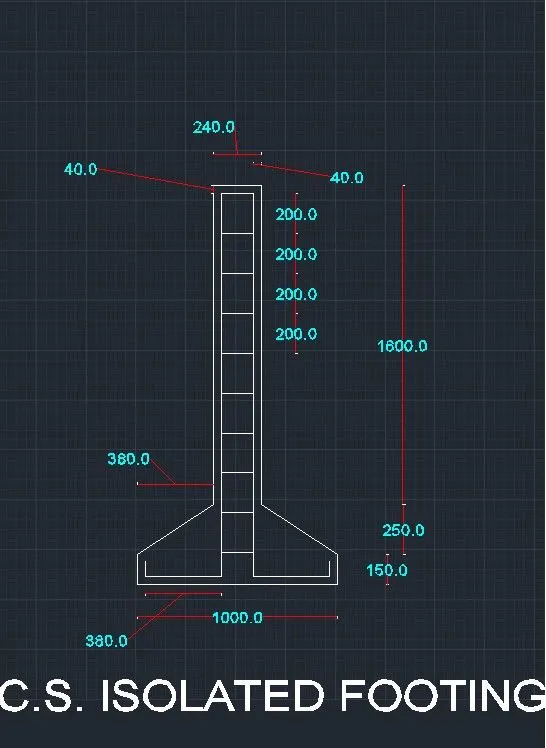
1. After defining the units using "UN" command, draw the line of 1000 mm followed by 150 mm by the help of ORTHO ON MODE (F8).
2. use the Trace command to get the next coordinate with X= 380, y= 250 and after that, join the line
3. draw the line of 1600 mm dimension followed by 200mm horizontal line.
4. track the midpoint of 1000 mm line using OBJECT SNAP mode .]
5. Take the mirror command using an axis defined by step 4.
6. After drawing the sketch, give the text & dimensions to the drawing.
7. Check the properties of Text, LINES & ARROWS etc. available in ANNOTATE Command to make the data nector to the reader.
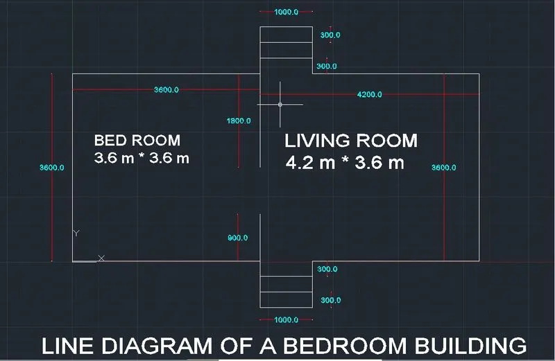
1. plot the first coordinate at origin.
2. second coordinate was (0,3600), third coordinate was (3600,3600), fourth one was (3600,1800).
3. plot fifth one as (3600,0), followed by (3600,900)and then (7800,0)and after that (7800,3600).
4. use break command between fifth & sixth coordinate to break at two points.
5.draw the two recatangles having (1000*300)on both sides along x axis.
6. after drawing the sketch, define the properties of Text, lines and arrows etc. using ANNOTATE Command as defined earlier.
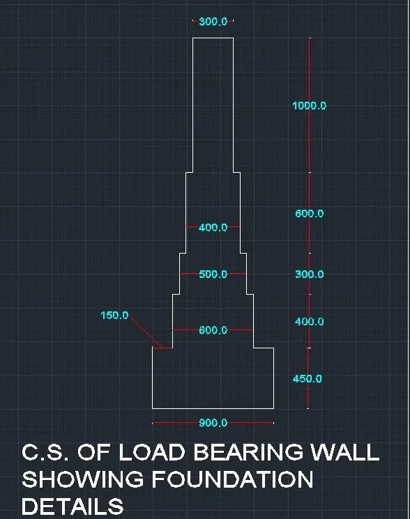
1. Define the Origin as well as the units before plotting the coordinates.
2. Use Line command to join the coordinates .
3. use the Trace command nested within line command to plot the point not in direct accessibility.
4. coordinate can be named as follows.
(0,0), (900,0),(900,450), (0,450), (150,450), (750,450), (150,850), (200,850),(700,850), (750,850),(200,1150),(250,1150), (650,1150), (700,,1150)
after defining the coordinates join them using line command
5. Define the properties of TEXT, LINES & ARROWS in the ANNOTATE TOOLBAR.
6.after defining, give the dimensions & text to the drawing as per the demand.
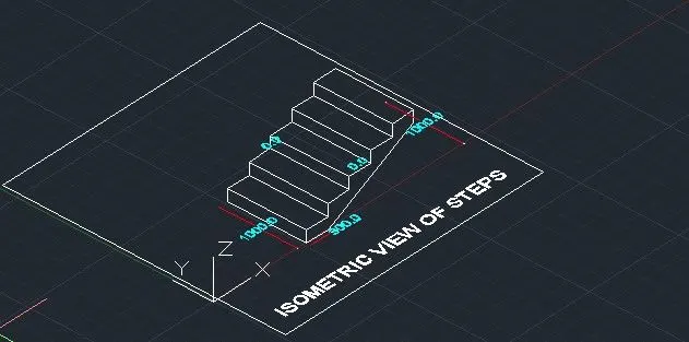
1. Define the origin using UCS command followed by UNITS through "UN" command.
2. Use F5 option to switch over from one plane to another coordinate system.
3. Use LINE command to draw a line of 1000 mm dimension followed by 300 units as thread while 150 units as Riser.
4. Every time for drawing riser & thread, we have to use F5 option to get an interchange into different plane.
5. After Drawing the Sketch, give the dimensions either using DIMLINEAR command or by ANNOTATE options available in HOME tab.
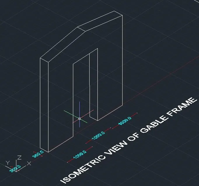
1. Firstly define the UN command followed by UCS command .
2. use LINE command to draw the lines of specific plane.'
3. To draw the lines of different plane, Use F5 option to switch over to differnt plane.
4. Judicious Use of Trace command Nested within LINE command helps in plotting the figure without drawing satellite/ pivot stations.
5. Define the properties of Text, LInes & arrows etc. available in the ANNOTATE Command.
6. Draw the Text & dimensions using ANNOTATE TOOLBAR given in HOME tab.
RESULT:
WE have defined the following properties to get the above attached images:
TEXT : (style REGULAR), (height 55), ARIAL, (color CYAN)
LINES & ARROWS: (dimension line RED), (Linetype BYLAYER), (arrows SINGLE ARROWS).
here we attached some screenshorts defining the properties hidden behind these sketches are: