Week 3 Challenge
Question 1:-
Effective length factor determination problem
- Height of column is 10 m and it is effectively restrained in mid height in one direction (in Z direction) but free to move in other direction (Y direction). Bottom of column is Fixed and top of column is Free.
- Calculate effective length factor of columns in following cases
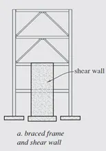
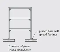
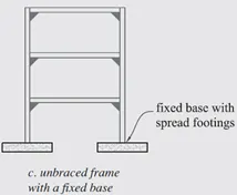
Given data:-
Height of column = 10m
Column is effectively restrained in mid height in one direction (in Z direction) but free to move in other direction (Y direction).
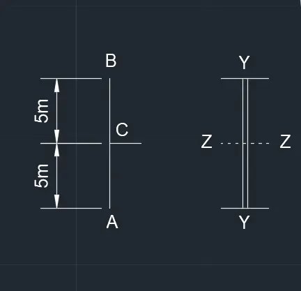
Therefore the actual length (L) is 5m.
a. Braced frame and shear wall:
As per IS 800 : 2007, Table 11.
The effective length factor for Bottom of column is fixed and Top of column is free = 2.0L
Le = 2.0 x 5m = 10m
b. Unbraced frame with a pinned base:
As per IS 800 : 2007, Table 11.
The effective length factor for Bottom of column is pinned and Top of column is free = 2.0L
Le = 2.0 x 5m = 10m
c. Unbraced frame with a fixed base:
As per IS 800 : 2007, Table 11.
The effective length factor for Bottom of column is fixed and Top of column is free = 1.2L
Le = 1.2 x 5m = 6m
Question 2:-
Design Axial strength determination of a column with its end conditions
Calculate the Axial compressive capacity of Column made up of Hot rolled ISMB 300 with flange cover plate of 200x12 mm on each flange having length of beam as 3 m. Assume the bottom of the column is Fixed and Top as Roller (Rotation Fixed, translation free). Yield strength of material fy= 250 N/mm2
Tip Steps:
- Determine new radius of gyration of compound section
- Using Buckling curve classification & slenderness ratio using table 9c in code, calculate compressive strength
- Using compressive strength, calculate design strength multiplying the cross sectional area.
Given data:-
- Section - Hot rolled ISMB 300 with flange cover plate of 200 x 12 mm on each flange.
- Unsupported Length of column is 3 m.
- Bottom of Column is fixed and Top as Roller (Rotation fixed, translation free)
- Fy is 250 N/mm2
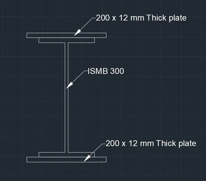
Answer:-
Step 1:-
Properties of built-up section:
The built-up column consist of one ISMB 300 and Two cover plates of 200 x 12 mm as shown above.
From steel section tables (SP 6 - Part 1),
Cross section area of ISMB 300 = 5626 mm2
Ixx of ISMB 300 = 8603.6 x 104 mm4
Iyy of ISMB 300 = 453.9 x 104 mm4
Cross section area of Plate = 2400 mm2
Moment of inertia of built-up section about xx-axis
Ixx = [8603.6 x 104 + 2 x 200 x 123 x (1/12) + 2 x Ah2]
= [8603.6 x 104 + 5.76 x 10⁴ + 2 x 2400 x (150+12/2)]
= [8603.6 x 104 + 5.76 x 10⁴ + 74.88 x 10⁴]
Ixx = 8684.24 x 104 mm4
Moment of inertia of built-up section about yy-axis
Iyy = [453.9 x 10⁴ + 2 x 12 x 2003 x (1/12)]
= [453.9 x 10⁴ + 1600 x 104 ]
Iyy = 2053.9 x 104 mm4
Step 2:-
Slenderness ratio:
Iyy is less than Ixx. Therefore ryy is Minimum.
Minimum radius of gyration rmin = (Iyy / A)1/2
= (2053.9 x 104 / 10426)1/2
rmin = 44.38 mm
Unsupported Length (L) = 3 m = 3000 mm.
Effective Length (Le) = 1.2 x L = 3600mm
Slenderness ratio of the column = (L/rmin ) = 3600/44.38 = 81.12
Step 3:-
Safe Load:
From IS 800 : 2007
For L/r = 81.12 and the steel having yeild stress, Fy is 250 N/mm2
Allowable working stress in compression
fcd = 138 N/mm2
Safe load carrying capacity of builtu-up section P = fcd x A = 138 x 10426 = 1438788 N
P = 1438.788 kN
Result:-
Design Strength = 1438.788 kN
Question 3:-
Design circular tube strut member for certain load
Design 2 m long tubular strut member to carry factored axial load of 400 kN. Assume the ends of the member are simply supported and the yield strength fy=210 Mpa. Also find Equivalent Square hollow sections.
Tip Steps:
- Calculate the area required from design compressive stress and Factored load on strut
- Choose a section satisfying the area calculated.
- Check limiting width to thickness ratio
- Find buckling class & slenderness ratio
- Using Buckling curve classification & slenderness ratio using table 9c in code, calculate compressive strength
- Using compressive strength, calculate design strength multiplying the cross sectional area.
Given data:-
Length of strut member = 2 m
Factored axial load = 400 kN
Fy = 210 N/mm2
Assume the ends of member are simply supported
Hence Le = 1.0 x L = 2 m = 2000 mm.
Answer:-
Required area of cross section = P / Fy
= 400 x 103 / 210
=1904.76 mm2
From IS 4923 : 1997, Table 1
For a circular hollow section of 125 outer bore dia = 139.7 thickness = 4.5, Area of circular section = 1910 mm2
For a square hollow section of 100x100x6 has a Area of square section = 2163 mm2
From IS 800 : 2007, Table 2
Limiting Width to Thickness ratio of circular section should be lesser than 88 e2
e = (250/Fy)1/2 = 1.09
D/t = 139.7 / 4.5 = 31.04
88 e2 = 95.92
Width to Thickness ratio of circular section is lesser than 88 e2
Hence safe.
From IS 800 : 2007, Table 10
Square tube Sections comes under class a
For circular section Slenderness ratio λ=L/rmin = 2000/47.8 = 41.84 < 180
For square section Slenderness ratio λ= L/rmin =2000/37.9
L/rmin = 52.77 < 180
Hence safe.
From table 9a of the code for fy = 210
For circular section fcd = 180 N/mm2
For square section fcd = 174.1 N/mm2
Hence, the design strength for circular section = 180 x 19.10 = 343.8kN.
Question 4:-
Design of laced column
Design a single laced column made up of two channels back to back of 10 m height to carry factored axial load of 1000kN. The lacings are bolted. Design of bolted connection not required.
Tip Steps:
- Calculate required Cross section area
- Assume a channel section and calculate the compressive capacity
- Find the appropriate spacing of channel
- Find spacing of lacings
- Calculate design forces –Transverse, compressive force in lacing bars
- Check if the assumed lacings are safe for calculated design forces.
- Check if effective slenderness ratio is within limit
Given data:-
Height = 10m
Factored axial load = 1000kN
Assume design stress of 125 N/mm2 (0.5 fy)
Required area =1000x103 / 125=8000 mm2
Answer:-
Assume the column to be built up of two ISMC 300 channels placed back-to-back
Cross section area of each channel = 4564 mm2
Cross section area of two columns (A) = 2 x 4564 = 9128 mm2
rxx = 118.1 mm
ryy = 26.1 mm
tf = 13.6 mm
tw = 7.6 mm
cyy = 23.6 mm
Ixx for two channel = 2 x 6362.8 x 104 mm4 = 12725.2 x 104 mm4
Iyy for one channel = 310.8 x 104 mm4
The distance back to back 'S' between the channels is so adjusted as to make rxx = ryy
L/rxx = 10 x 103 / 118.1 = 84.67
L/r of the built-up section should be taken as 1.05 x 84.67 = 88.90
fcd taken from code for given rxx = 120 N/mm2
Permissible axial load = 9128 x 120 = 1095 kN > 1000 kN.
Hence the section is safe.
Spacing of channels = 12725.2 x 104 = 2 (Iyy + A (S/2 +Cyy)2)
=2 x (310.8 x 104 + 4564 (S/2 +23.6)2)
solving the above equation S = 183.1mm
Design of Lacing:
Using the single lacing bar inclined at 45 degree with the column axis.
Lacing system of the built-up section using single lacing system with the inclination of lacing bar gauge length g = 50 mm for 90 mm flange
Spacing of lacing bars Lo= 2 x (183 + 50 x 2) cot 45
= 2 x 283 x 1 = 566 mm
For a single column element, slenderness ratio Lo / ryy should be < 0.7 x L/r of whole column
566 / 26 = 21.76 < 0.7 x 88.98=62.3
Hence safe.
Transverse shear force (V) = (2.5 /100) x axial load = (2.5/100) x 1000 x 103 = 25 kN = 25000 N
Transverse shear in each panel = V/N = 25000/2 = 12500 N
Compressive force in the lacing bar =(V/N) cosec45
= 12500 x1.414
=17675 N
Question 5:-
Design of battened column
Design a battened column made up of two channels back to back of 5 m height to carry factored axial load of 2000kN. The Battens are welded. Design of weld not required. Use Hot rolled channel sections.
Tip Steps:
- Calculate required Cross section area
- Assume a channel section and calculate the compressive capacity
- Find the appropriate spacing of channel
- Find spacing of battens & size of end/intermediate battens
- Calculate design forces –Transverse, longitudinal shear, Moment
- Check if the assumed battens are safe for calculated design forces.
Given data:-
Height = 5m
Axial load= 2000 kN
Assume design stress of 150 N/mm2 (0.6 fy)
Required area =2000 x 103 / 150 = 13333 mm2
Assume the column to be built up of two ISMC 350 channels placed back-to-back
Cross section area of each channel = 5366 mm2
Cross section area of two columns (A) = 2 x 5366 = 10732 mm2
rxx = 136.6 mm
ryy = 28.3 mm
tf = 13.5 mm
tw = 8.1 mm
cyy = 24.4 mm
Ixx for two channel = 2 x 10008 x 104 mm4 = 20016 x 104 mm4
Iyy for one channel = 430.6 x 104 mm4
The distance back to back 'S' between the channels is so adjusted as to make rxx = ryy
L/rxx = 5 x 10³ / 136.6 = 36.60
fcd taken from IS 800 : 2007 Table 9c for given rxx = 202.4 N/mm2
Permissible axial load = 10732 x 202.4 = 2172 kN > 2000 kN.
Hence the section is safe.
Spacing of channels = 20016 x 104 = 2 (Iyy + A (S/2 +Cyy)2)
=2 x (430.6 x 104 + 5366 (S/2 +24.4)2)
solving the above equation S = 333.4 mm
Spacing of battens Lo/ryy should be less than 50 or 0.7x L/ryy
Lo/ryy < 0.7 x 36.6
Lo < 0.7 x 36.6 x 28.3 = 725 mm
Also, Lo/ryy should be less than 50
Lo/ryy < 50
Lo < 50 x ryy = 50 x 28.3 = 1415 mm
Hence provide batten at spacing 725 mm
Size of end battens
Overall depth of batten = 334 + 2 x Cyy
= 334 + 2 x 24.4= 383 mm
Provide 60 mm overlap of batten on channel flange for welding
Length of batten = 334 x 2 x 60 = 454 mm = 460 mm
Thickness of battens = 1/50 x 460 = 9.2 mm
Provide batten size = 460 x 390 x 9.2 mm
Size of intermediate battens
Overall depth = 3/4 x 390 = 293 mm
Provide 460 x300x 9.2 mm.