Week 3 Challenge
Q1]
AIM: -
(I). State the primary load cases to be considered for design.
(II). Define One – Way slab?
(III). What is the value of unit weight of structural steel and soil?
(IV). Name few sections that can be defined using Properties tab in STAAD Pro.
(V). Define Primary Beams.
PROCEDURE: -
(I)
The primary load cases to be considered for design are:
Dead Load
Live Load/Imposed Load
Wind Load
Earthquake Load
(II)
The one-way slab is supported by parallel walls or beams, and whose length to breadth ratio is equal to or greater than two and it bends in only one direction (spanning direction) while it is transferring the loads to the two supporting walls or beams, because of its geometry.
Mathematically,
(Longer Span / Shorter Span) ≥ 2
In other words, the one-way slab is supported by beams in such a way that the load is carried along one direction.
The shorter span of the one-way slab is provided with the main reinforcement while the longer span is provided with the distribution reinforcement.
Some of the prominent examples of one-way slabs are the cantilever slabs, chajjas, and verandahs.
(III)
Unit weight of Steel = 7850 Kg/m^3
Unit weight of soil = 1800 Kg/m^3
(IV)
Names of the sections that can be defined using Properties tab in STAAD Pro:
Circular section
Rectangular section
Trapezoidal section
Tee section
General section
Tapered Tube
(V)
The beams that are connecting columns for transferring loads of a structure directly to the columns are known as primary beams.
Usually, primary beams are shear connected or simply supported and they are provided in a regular building structure.
The depth of the primary beams is always greater than secondary beams. Primary beam act as a medium between columns and secondary beams.
RESULT: -
(I). Stated the primary load cases to be considered for design.
(II). Defined One – Way slab.
(III). Mentioned the value of unit weight of structural steel and soil?
(IV). Named few sections that can be defined using Properties tab in STAAD Pro.
(V). Defined Primary Beams.
Q2]
AIM: -
(I). State the factors and parameters that influence the design pressure intensity of a high-rise building.
(II). Mention the load transfer process of a Reinforced Concrete Building.
PROCEDURE: -
(I)
Pz = 0.6 Vz^2
Pz = Design wind pressure
Vz = Design Speed
The factors and parameters that influence the design pressure intensity of a high-rise building are:
Vz = Vb x K1 x K2 x K3
Vb = Wind Speed
K1 = Probability Factor
K2 = Terrain, Height and Structure size factor
K3 = Tropography Factor
(II)
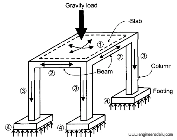
The load transfer process of a Reinforced Concrete Building is
Slab
Secondary Beam
Primary Beam
Columns
Foundation
RESULT: -
(I). Stated the factors and parameters that influence the design pressure intensity of a high-rise building.
(II). Mentioned the load transfer process of a Reinforced Concrete Building.
Q3]
AIM: -
(I). Differentiate One-Way and Two way slabs. Elaborate each slab type.
(II). Explain the concept of secondary beams with proper sketch.
(III). Mention the Primary load cases.
a. State the Indian Standards for each load case
b. Detail the parameters of each load case
c. Brief each load case
(IV). Detail the steps involved in assigning Properties and Support to a model using STAAD Pro sequentially.
(V). Brief the steps to be followed to create and assign secondary beams in STAAD Pro
PROCEDURE: -
(I)
| One-Way Slab | Two-way Slab | |
| a. | The one-way slab can be defined as the type of slab in which the ratio of the longer span to the shorter span is greater than two. | The two-way slab can be defined as the type of slab in which the ratio of the longer span to the shorter span is less than two. |
| b. | The bending moment occurs only in one direction. | The bending moment occurs in two directions. |
| c. | L/B ratio is greater than 2. | L/B ratio is less than 2. |
| d. | In a one-way slab, the crank is provided in two directions. | In a two-way slab, the crank is provided in four directions. |
| e. | In a one-way slab, the main reinforcement is provided in a short span and distribution reinforcement is provided in a long span. | In a two-way slab, the main reinforcement is provided in both directions. |
| f. | The one-way slab is supported by a beam on two opposite sides only. | The two-way slab is supported by the beam on all four sides. |
| g. | In a one-way slab, the load is carried in one direction perpendicular to the supporting beam. | In a two-way slab, the load is carried in both directions. |
| h. | The one-way slab is economical up to a span of 3.6 meters. | The two-way slab is economical for panel sizes up to 6m x 6m. |
| i. | In a one-way slab quantity of steel required is less. | In a two-way slab quantity of steel is more as compared to the one-way slab. |
| j. | It is mostly used for culverts, bridges, etc. | It is mostly used for residential buildings, water tanks, etc. |
(II)
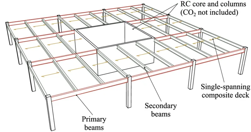
SECONDARY BEAMS:
The beams that are connecting primary beams for transferring loads of a structure to the primary beams are known as primary beams. These beams are provided for supporting and reducing the deflection of beams and slabs.
(III)
(a)
For Dead load : IS 875 Part 1
Live load : IS 875 Part 2
Wind Load : IS 875 Part 3
Seismic Load : IS 1893 Part 1
(b)
DEAD LOAD:
Dead load = volume of member x unit weight of materials
By calculating the volume of each member and multiplying by the unit weight of the materials from which it is composed, an accurate dead load can be determined for each component.
Parameters are:
volume of member
Unit weight of member
LIVE LOAD:
All unfixed items in a building such as people and furniture result in a 'live' load on the structure. Live loads are exerted in the vertical plane. Live loads are variable as they depend on usage and capacity.
Parameters are:
Usage
Occupancy
Type of structure.
Capacity.
Area.
WIND LOAD:
The force exerted by the horizontal component of wind is to be considered in the design of building. Wind loads depends upon the velocity of wind, shape and size of the building.
Parameters are:
Geographic location
Terrain category
Height of building
Shielding
Building shape
SEISMIC LOAD:
Seismic loading depends, primarily on Seismic hazard, Geotechnical parameters of the site, and Structure's natural frequency etc
Parameters are:
Type of Seismic zone
Type of soil condition
Damping ratio
Response reduction factor
(C)
DEAD LOAD:
Dead load on a structure is the result of the weight of the permanent components such as beams, floor slabs, columns and walls. These components will produce the same constant 'dead' load during the lifespan of the building. Dead loads are exerted in the vertical plane
LIVE LOAD:
All unfixed items in a building such as people and furniture result in a 'live' load on the structure. Live loads are exerted in the vertical plane. Live loads are variable as they depend on usage and capacity.
WIND LOAD:
Wind load is considered to be dynamic as it varies greatly in intensity from time to time. Wind loads are very different to dead loads and live loads.Wind loads typically act laterally on walls and may act up and down on roofs.
SEISMIC LOAD:
Seismic loading is one of the basic concepts of earthquake engineering which means application of a seismic oscillation to a structure. It happens at contact surfaces of a structure either with the ground or with adjacent structures. Seismic loading depends, primarily on seismic hazard, geotechnical parameters of the site, and structure's natural frequency etc
(IV)
Click on PROPERTIES
Properties dialogue box opens
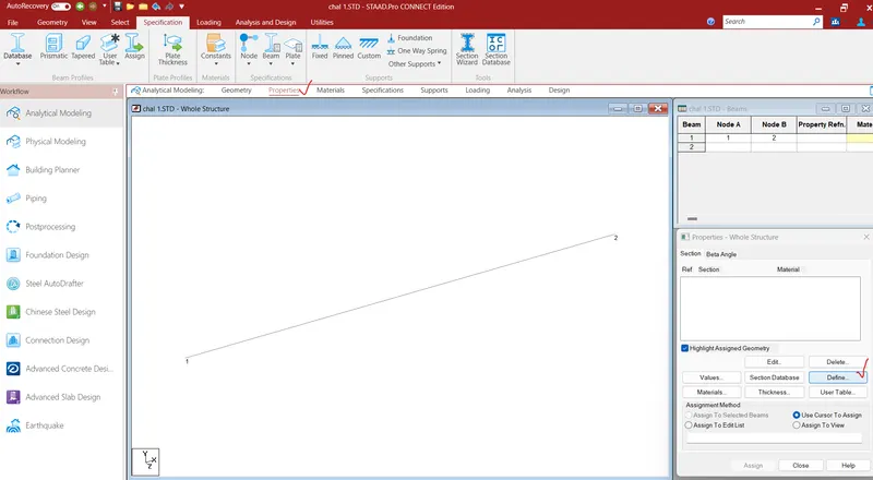
Click on Define
Add the Section here
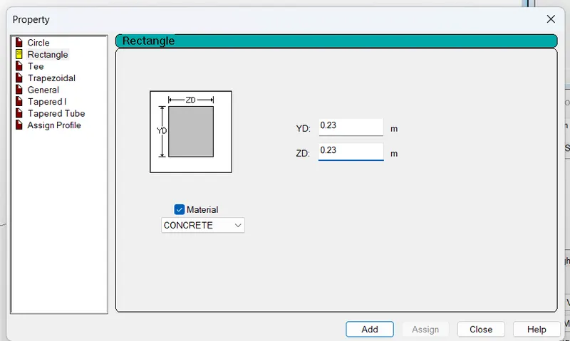
Select the section, Rectangular/Circular etc,
Select the material type concrete, steel , aluminium
Select Rectangle and fill the data required.
YD= 0.23m, ZD=0.23m, Material = Concrete and
click Add.
Select Materials, from the Material Tab and assign it to the created beam.
It can be checked by selecting the Concrete Title, then we can see that the created beam lines will be highlighted.
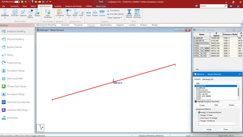
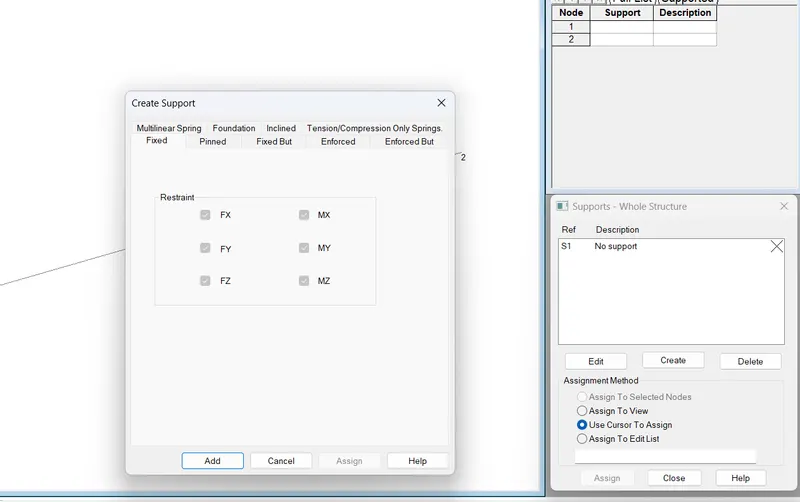
Select SUPPORTS TAB
Supports-Whole Structure dialogue box opens
Click on create option
select Fixed and click Add.
(V)
First create a simple model by using node in staad Pro
Click on Create beam option and create a beam in the direction of x and z axis
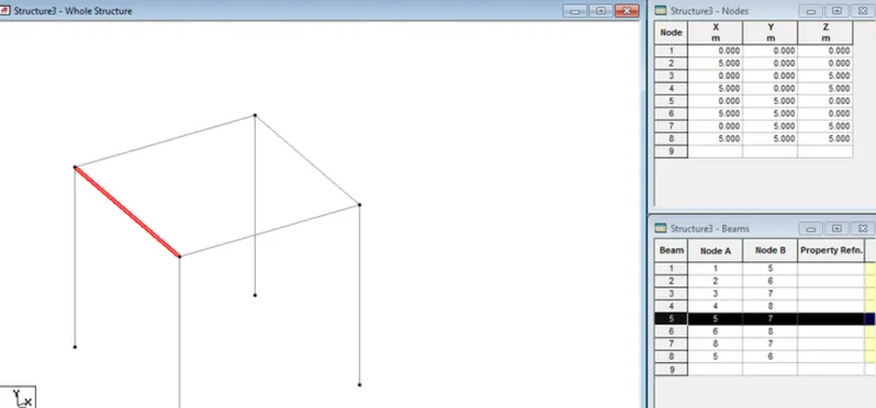
Click on the primary beam in the section
Right click and add new node in the beam section a node will be added
Click on the create beam
Add New beam between Nodes.
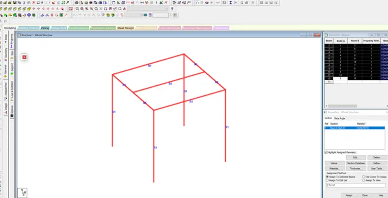
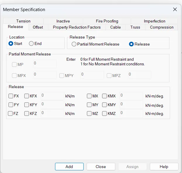
Go to the Specification
Select Beam
Member Specification dialogue box opens
Click on Release
Click on Start and Tick on Fx and Mz and click Add.
Now Click on End and Tick Fx and Mz and click Add
Now Assign to the selected Beam
RESULT: -
(I). Differentiated One-Way and Two way slabs.
(II). Explained the concept of secondary beams with proper sketch.
(III). Mentioned and elaborated each load case.
(IV). Explained the steps involved in assigning Properties and Support to a model using STAAD Pro sequentially.
(V). Explained the steps to be followed to create and assign secondary beams in STAAD Pro.
PRACTICAL:
AIM: -
(I). Calculate the wind pressure for the given building
(II). Calculate the Dead load and Live load for the building with reference to IS standards
(assume suitable sections )
PROCEDURE: -
(I)
GIVEN DATA
a. Building Dimension : 20m x 30m x 20m height RCC
b. Building usage : Hospital block in city centre
c. Location : Darjeeling
Wind Pressure (Pz) = 0.6 Vz^2
Vz = Vb x k1 x k2 x k3
The Structure in category - 4 and Class B and designed for 100 years.
From IS 875 Part 2
Vb = 47 m/s
K1 = 1.07 (Table 1, Clause 5.3.1)
K2 = 0.76 (Table 2, Clause 5.3.2.2) (Categort- 4 ; Class - B)
k3 = 1 (Clause 5.3.3.1)
Hence; Vz = 47 x 1.07 x 0.76 x 1
= 38.22 m/s
And Pz = 0.6 (38.22)^2
= 0.87 N/m^2
| Height | K2 | Vz | Pz | Pz in KN |
| 3 | 0.76 | 38.22 | 876.47 | 0.87 |
| 6 | 0.76 | 38.22 | 876.47 | 0.87 |
| 9 | 0.76 | 38.22 | 876.47 | 0.87 |
| 12 | 0.76 | 38.22 | 876.47 | 0.87 |
| 15 | 0.76 | 38.22 | 876.47 | 0.87 |
| 18 | 0.76 | 38.22 | 876.47 | 0.87 |
| 20 | 0.76 | 38.22 | 876.47 | 0.87 |
(II)
DEAD lOAD
Unit Weight of Concrete = 25 KN/m^2
Unit Weight of PCC = 22 KN/mm^2
Unit Weight of Brick Wall = 18 KN/m^2
Perimeter of building = 20+20+30+30=100m
SELF WEIGHT OF BUILDING:
= (Weight of one Slab x 7) + Weight of Wall
= (25 x 0.150 x 30x20X7) + (18 x 3 x 100 x 0.23X5) + ( 18 x 2 x 100 x 0.23X1)
= 22788 kN
LOADS ON FLOOR SLAB:
Interior partitions = 1 kN/m^2
Floor Finish(100mm) = 2.2 kN/m^2
Miscellaneous = 0.5 kN/m^2
Total SDL = 4.0 kN/m2
RC Parapet wall at Roof level = 5 kN/m
= 5x100(perimeter of building = 20+20+30+30=100m)
= 500 kN
Total SDL = 4x20x30
= 2400 kN
Total Dead load =22788 + 2400 + 500
= 25688 kN
LIVE LOAD
Assume live load = 3KN/m^2
Live Load = 20 x 30 x 3 = 1800 KN
Total Live Load = 1800 x no of floors
= 1800 x 6
= 10800 KN
RESULT: -
(I). Calculated the wind pressure for the given building
| Height | K2 | Vz | Pz | Pz in KN |
| 3 | 0.76 | 38.22 | 876.47 | 0.87 |
| 6 | 0.76 | 38.22 | 876.47 | 0.87 |
| 9 | 0.76 | 38.22 | 876.47 | 0.87 |
| 12 | 0.76 | 38.22 | 876.47 | 0.87 |
| 15 | 0.76 | 38.22 | 876.47 | 0.87 |
| 18 | 0.76 | 38.22 | 876.47 | 0.87 |
| 20 | 0.76 | 38.22 | 876.47 | 0.87 |
(II). Calculated the Dead load and Live load for the given building with reference to IS standards.
Total Dead load = 25688 kN
Total Live Load = 10800 KN