Week 3 Challenge
Q1.1. State the primary load cases to be considered for design.
ANS :
The primary load cases to be considered for design are
Dead Load
Live load / Imposed load
Wind Load
Snow load
Earthquake load
Q1.2. What is One – Way slab?
ANS :
The one-way slab is a slab, which is supported by parallel walls or beams, and whose length (l) to breadth (b) ratio is equal to or greater than two and it bends in only one direction (spanning direction) while it is transferring the loads to the two supporting walls or beams, because of its geometry.
l/b ≥ 2
Q1.3. What is the value of unit weight of structural steel and soil?
ANS :
As per IS 875 part 1
Unit weight of Structural steel is 7840 Kg/cu.m
Unit weight of soil is 18 KN/cu.m
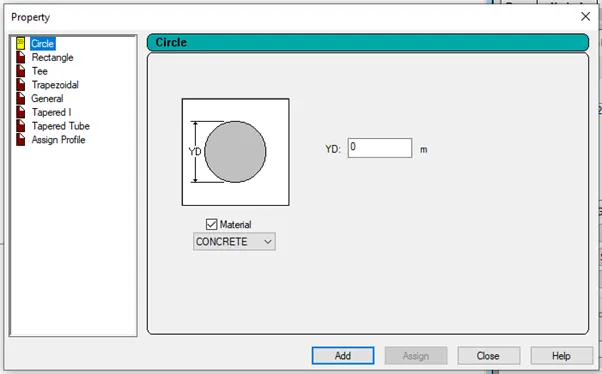
Q1.4. Name few sections that can be defined using Properties tab in STAAD Pro.
ANS :
Circular section
Rectangular section
Tee section
Trapezoidal section
General section
Tapered I section
Tapered tube section
Q1.5. Define Primary Beams.
ANS :
The beams that are connecting columns for transferring loads of a structure directly to the columns are known as primary beams. Usually, primary beams are shear-connected or simply supported and they are provided in a regular building structure. The depth of the primary beams is always greater than the secondary beams.
Q2.1. State the factors and parameters that influence the design pressure intensity of a high-rise building.
ANS :
The design speed can be governed by the formula
Vz = Vb x k1 x k2 x k3 x k4
Where,
Vz = Basic wind speed, based on the location of the project in India
k1 = Risk coefficient factor
k2 = Terrain and height factor
k3 = Topography factor
k4 = Importance factor
The design wind pressure is given by the formula
Pz = 0.6 x Vz^2
Q2.2. Mention the load transfer process of a Reinforced Concrete Building.
ANS :
The load transferring process of a reinforced concrete building is
Slab > Primary Beam > Secondary beam > Column > Foundation > Ground
Q3.1. Differentiate One-Way and Two way slabs. Elaborate each slab type.
ANS :
One way slab
- The slabs are supported by the beams on the two opposite sides
- The loads are carried only in one direction
- The ratio of longer span to shorter span is equal to greater than 2 (l/b ≥ 2)
- Main reinforcement provided only in one direction (i.e; shorter side)
- The deflected shape is like cylindrical
Two way slab
- The slabs are supported on all the four directions
- The loads are carried along both directions
- The ratio of longer span to shorter span is less than 2 (l/b < 2)
- Main reinforcement bars are provided in both directions
- The deflected shape is like dish
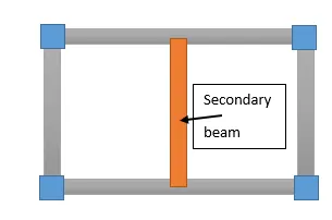
Q3.2. Explain the concept of secondary beams with proper sketch.
ANS :
The beams that are connecting primary beams for transferring loads of a structure to the primary beams are known as secondary beams. These beams are provided for supporting and reducing the deflection of beams and slabs.
Q3.3. Mention the Primary load cases.
a.State the Indian Standards for each load case
ANS :
Dead Load – IS 875 Part 1
Live Load – IS 875 Part 2
Wind Load – IS 875 Part 3
Snow Load – IS 875 Part 4
Earthquake Load – IS 1893 and IS 13920
b.Detail the parameters of each load case
ANS :
Parameters of live load depends on the building type like Residential Building, Commercial Building, Industrial Building etc. The parameters may include room loads, Balcony load etc.
Parameters of Dead load Includes self weight, Volume of the structure etc
c.Brief each load case
ANS :
Dead Load :
The dead load is defined as the continuous load in a structure i.e the load of machine etc and this load caused by the weight of the members that are permanently attached to the particular structure
The dead load of the structure comprised of the load of the column, load of the beam , loads of the floor slab, roofing,walls, the load of the windows or may be the load of the electrical fixture. All the loads which is permanent on the structure is called as the dead load of the structure.
Some of the Dead Load(Unit Weight) of the following materials:
Cement : 1440 Kg/cu.m
Steel : 7850 Kg/cu.m
Sand : 1600 Kg/cu.m
Concrete : 2400 Kg/cu.m
RCC : 2500 Kg/cu.m
Dead load factor is 1
Live load :
Live loads are the loads that are fully or partially vary from time to time on the structure.
Live loads are not constant loads throughout the life span of a structure.
Live loads may vary time to time according to its usage or the occupancy.
Live load may vary depends on the type of the structure such as the residential building, commercial building, industrial building etc.
For residential building we use 3KN/sq.m Live Load
Live loads on floors and the roofs consists of all loads which are temporarily placed on the structure. Some of the live loads (Unit weight) are :
All rooms and kitchen : 2 KN/sq.m
Bathrooms and toilets : 2 KN/sq.m
Balcony : 3 KN/cu.m
Staircase/Corridors : 3 KN/cu.m
Wind Load :
Wind load is a force on a structure that is raising from the impact of the wind. Wind load is an important load case for the structure. We consider this type of load where the structure is situated or located in the hilly areas of the mountain areas where we can expect high speed of the winds that can affect the structure. In those areas we need to consider the wind loads
Mainly we calculate the wind loads for the roof of the structure.
Earthquake Load :
Earthquake loads or seismic loads is also an important load case that needs to be considered while designing and analysing of the high rise structure of the building
Mainly we considered this type of loads where there are high chances of earthquakes or we can say we have to consider this load in the earthquake prone areas, where there is a high risk of earthquake
3.4. Detail the steps involved in assigning Properties and Support to a model using STAAD Pro sequentially.
ANS :
Steps involved in assigning properties
Go to Properties tab select define in that select the section like rectangular or circular or any other section and click on add and close the dialogue box after that select the property and select assign to selected beam and click on assign. Hence the created property is assigned to the beam
Steps involved in assigning Support
Go to support tab select create in that select the support which need to be added to the beam and click on add and close the dialogue box after that select the support and select use cursor to assign and select the nodes where the support to be assigned. Hence the created support is assigned to the beam
3.5. Brief the steps to be followed to create and assign secondary beams in STAAD Pro
ANS :
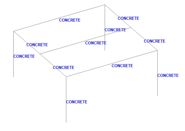
Open the STAA.Pro software and create a new project
Go to Geometry tab and create columns and beams by using nodes

Click on add beam and draw the beam using beam cursor
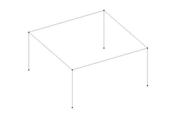
Now primary beams are created
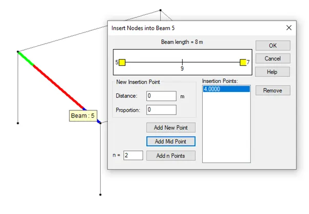
Select a primary beam and right click and select insert nodes you will get a dialogue box in that select Add mid point so that the nodes are created and secondary beam is drawn
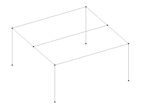
Go to properties tab and add rectangular section for beams and columns
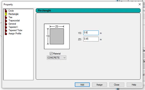
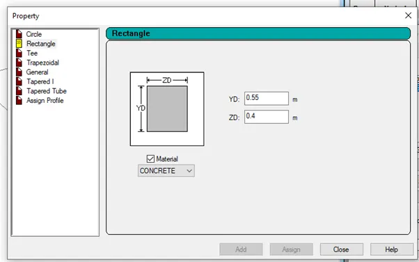
And select the option add to selected beam and assign the property to the respective column and beam
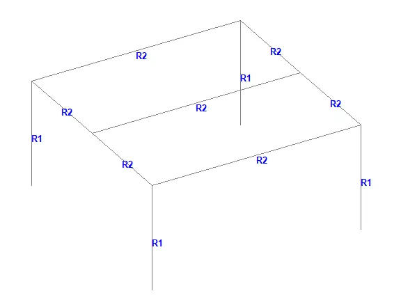
Go to material tab and assign the concrete material to the beams and columns
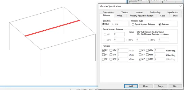
Go to specification tab in the select beam and select Fx and Mz so that secondary beam is acting as simply supported beam
And assign it to the selected beam
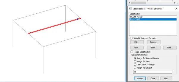
Hence the secondary beam is created
Practical
1.Calculate the wind pressure for the given building
a. Building Dimension : 20m x 30m x 20m height RCC
b. Building usage : Hospital block in city centre
c. Location : Darjeeling
ANS :
Wind Pressure, Pz = 0.6 Vz^2
Where, Vz = Vb x k1 x k2 x k3 x k4
Vb = Wind speed at the Darjeeling location = 47
K1 = Risk coefficient = 1.07
K2 = Terrain height and structure factor = 0.8
K3 = Topography factor = 1.0
K4 = Importance factor = 1.0
Vz = Vb x k1 x k2 x k3 x k4
Vz = 47 x 1.07 x 0.8 x 1.0 x 1.0
Vz = 40.232 m/s
Pz = 0.6 Vz^2
Pz = 0.6 x 40.232^2
Pz = 971.168 N
Wind pressure, Pz = 0.971 KN
2.Calculate the Dead load and Live load for the above building with reference to IS standards ( assume suitable sections )
ANS :
Dead load due to slabs :
Assuming the slab thickness of 150mm
Dead load due to slabs = Length x Breadth x Height x Slab thickness
Dead load due to slabs = 20 x 30 x 25 x 0.15
Dead load due to the slabs = 225 KN
Total dead load due to all the slabs = 5 x dead load due to the slabs = 5 x 225 = 1125 KN
Dead load due to beams :
Assuming the beam of cross section 450 x 550
Dead load due to beam = Size of beam x height
Dead load due to beam = 0.45 x 0.55 x 25
Dead load due to beam = 6.18 KN/m
Dead load due to beams = 7 KN/m
Superimposed loads due to partition walls :
Assuming 150mm thickness of brickwork
Height of the brickwork = Floor height – depth of the beam
Height of the brickwork = 3.75 – 0.55
Height of the brickwork = 3.2 meters
Therefore, the dead load due to the brick masonry partition = 3.2 x 0.15 x 18 = 8.64 KN/m
The dead load due to the brick masonry partition = 8.64 KN/m
Live load :
We can calculate the live load of a given structure by using the IS 875 Part 2, which states different live load values for different rooms.
As the building given is Hospital building all the proposed live load values for hospital building according to the IS 875 Part 3 has been listed below
|
OCCUPANCY |
LIVE LOAD |
|
For ward rooms, dressing rooms, dormitories and lounges |
2.0 KN/sq.m |
|
Kitchen and Laboratory |
3.0 KN/sq.m |
|
Dining room and Cafeteria |
3.0 KN/sq.m |
|
Toilets and Bathrooms |
2.0 KN/sq.m |
|
X-ray rooms and operating rooms |
3.0 KN/sq.m |
|
Office and OPD room |
2.5 KN/sq.m |
|
Corridor and Passages |
4.0 KN/sq.m |