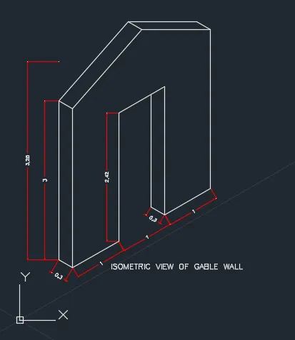
Creating a Floor plan, Footing detail and Isometric view using AutoCad
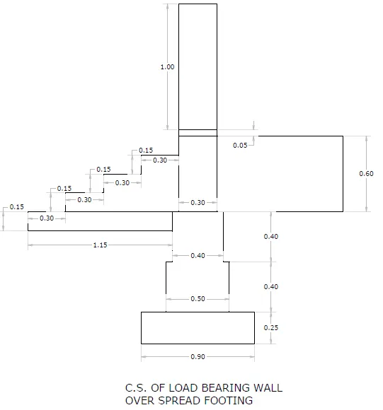
Q1. C1
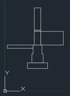
AIM : To draw the figure C1 in AutoCAD
PROCEDURE
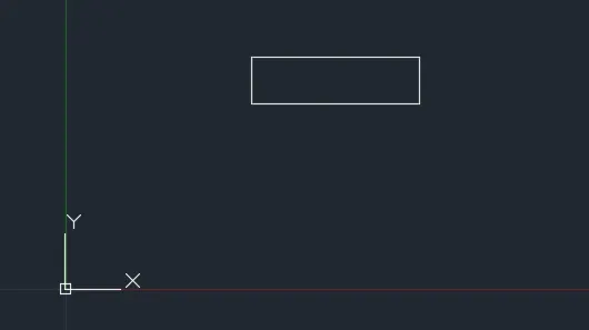
Type rectangle or rec in command box and press enter
Specify first corner point : 1,1 and press enter
Specify other corner point : @0.9,0.25 and press enter
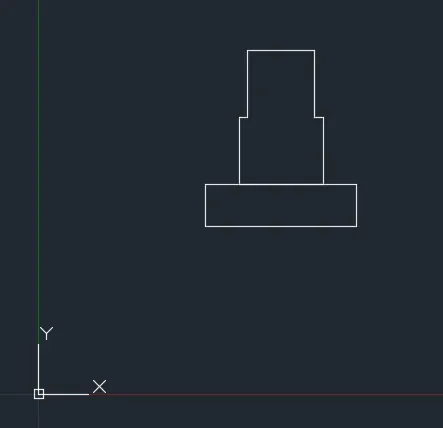
Type polyline or pl in command box and press enter
Specify start point: 1.2,1.25 and press enter
Specify next point : @0,0.4 and press enter
Specify next point : @0.05,0 and press enter
Specify next point : @0,0.4 and press enter
Specify next point ]: @0.4,0 and press enter
Specify next point : @0,-0.4 and press enter
Specify next point : @0.05,0 and press enter
Specify next point : @0,-0.4 and press enter
Specify next point : C (close the poly line)
Type rectangle or rec in command box and press enter
Specify first corner point : 1.3,2.05 and press enter
Specify other corner point : @0.3,0.6 and press enter
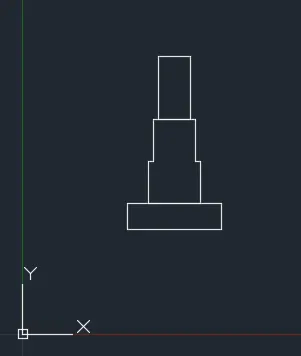
Type rectangle or rec in command box and press enter
Specify first corner point : 1.3,2.65 and press enter
Specify other corner point : @0.3,0.05 and press enter
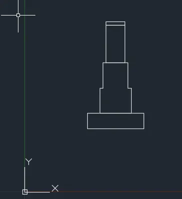
Type rectangle or rec in command box and press enter
Specify first corner point : 1.3,2.7 and press enter
Specify other corner point : @0.3,1 and press enter
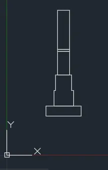
Type rectangle or rec in command box and press enter
Specify first corner point : 1.6,2.05 and press enter
Specify other corner point : @1,0.6 and press enter
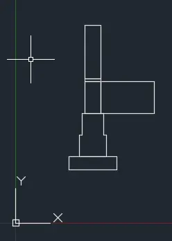
Type rectangle or rec in command box and press enter
Specify first corner point or [Chamfer/Elevation/Fillet/Thickness/Width]: 1.25,2.05
Specify other corner point or [Area/Dimensions/Rotation]: @-1.15,-0.15
Type polyline or pl in command box and press enter
Specify start point: Click on the top edge of the rectangle
Specify next point : @0.3,0 and press enter
Specify next point : @0,0.15 and press enter
Specify next point : @0.3,0 and press enter
Specify next point : @0,0.15 and press enter
Specify next point : @0.3,0 and press enter
Specify next point : @0,0.15 and press enter
Specify next point : @0.3,0 and press enter
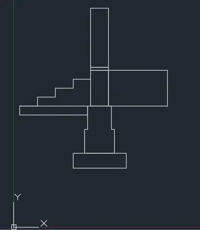
RESULT
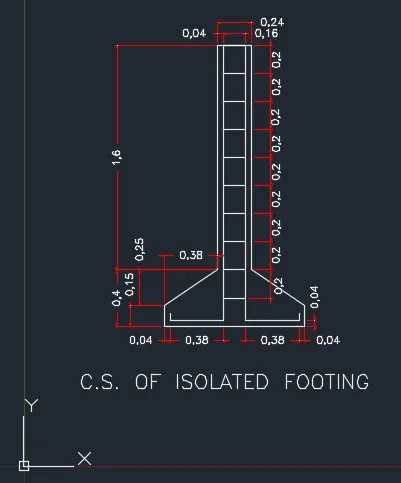
Figure C1 drawn using rectangle tool, polyline tool, Dimension tool and using Relative rectangular coordinate system
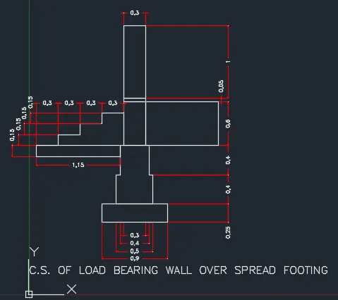
Q2. C2
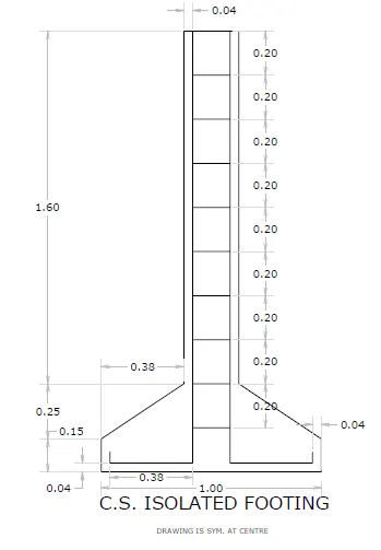
AIM : To draw the figure C2 in AutoCAD
PROCEDURE
Type polyline or pl in command box and press enter
Specify start point: 1,1 and press enter
Specify next point : @1,0 press enter
Specify next point : @0,0.4 press enter
Specify next point : @-0.38,0 press enter
Specify next point : @0,1.6 press enter
Specify next point: @-0.24,0 press enter
Specify next point : @0,-1.6 press enter
Specify next point : @-0.38,0 press enter
Specify next point : C (close the polyline)
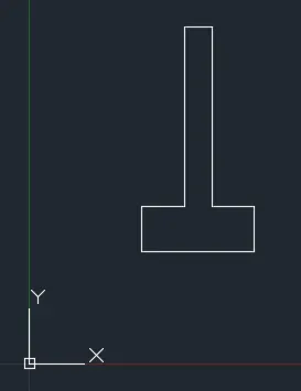
Type chamfer in command box and press enter
(TRIM mode) Current chamfer Dist1 = 0.0000, Dist2 = 0.0000
Select first line : D (distance)
Specify first chamfer distance : 0.38 and press enter
Specify second chamfer distance : 0.25 and press enter
Select first line : horizontal line at right side (west)
Select second line : vertical line at top
Type chamfer in command box and press enter
(TRIM mode) Current chamfer Dist1 = 0.3800, Dist2 = 0.2500
Select first line : horizontal line at left side (east)
Select second line : vertical line at top
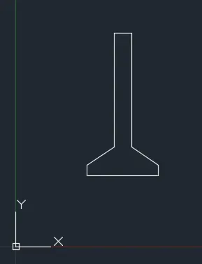
Type polyline or pl in command box and press enter
Specify start point: 1.04,1.09 and press enter
Specify next point : @0,-0.05 and press enter
Specify next point : @0.38,0 and press enter
Specify next point : @0,1.96 and press enter
Specify next point : @0.16,0 and press enter
Specify next point : @0,-1.96 and press enter
Specify next point : @0.38,0 and press enter
Specify next point : @0,0.05 and press enter
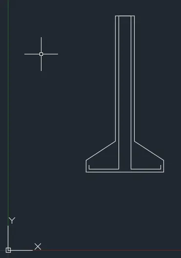
Type line or l in command box and press enter
Specify first point: 1.42,3 and press enter
Specify next point : 0.16 and press enter
Type offset or o in command box and press enter
Specify offset distance : 0.2 and press enter
Select object to offset : move the cursor down and click
Select object to offset : move the cursor down and click
Select object to offset : move the cursor down and click
Select object to offset : move the cursor down and click
Select object to offset : move the cursor down and click
Select object to offset : move the cursor down and click
Select object to offset : move the cursor down and click
Select object to offset : move the cursor down and click
Select object to offset : move the cursor down and click
Press esc to exit the command
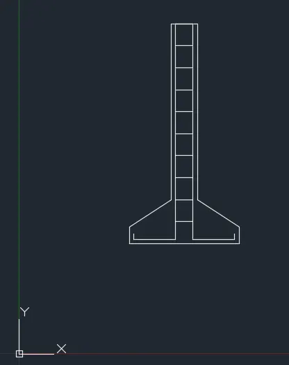
RESULT
Figure drawn C2 using polyline tool, chamfer tool, offset tool, dimension tool and using Relative rectangular coordinate system
Q3. C3
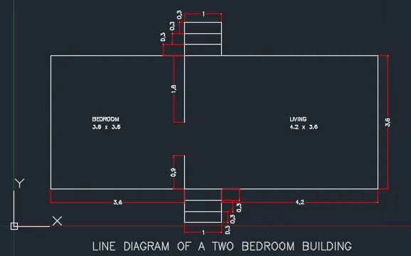
AIM : To draw the figure C3 in AutoCAD
PROCEDURE
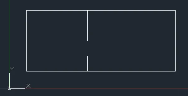
Type rectangle or rec in command box and press enter
Specify first corner point : 1,1 and press enter
Specify other corner point : @8.8,3.6 and press enter
Type line or l in command box and press enter
Specify first point: 4.6,1 and press enter
Specify next point : @0,0.9 and press enter
Type line or l in command box and press enter
Specify first point: 4.6,4.6 and press enter
Specify next point : @0,-1.8 and press enter
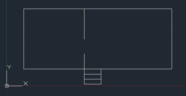
Type line or l in command box and press enter
Specify first point: 4.6,1 and press enter
Specify next point or [Undo]: @0,-0.9 and press enter
Specify next point or [Undo]: @1,0 and press enter
Specify next point or [Close/Undo]: @0,0.9 and press enter
Type offset or o in command box and press enter
Specify offset distance : 0.3 and press enter
Select object to offset : move the cursor up and click
Select object to offset : move the cursor up and click
Type line or l in command box and press enter
Specify first point: 4.6,4.6
Specify next point or [Undo]: @0,0.9
Specify next point or [Undo]: @1,0
Specify next point or [Close/Undo]: @0,-.9
Type offset or o in command box and press enter
Specify offset distance : 0.3 and press enter
Select object to offset : move the cursor up and click
Select object to offset : move the cursor up and click
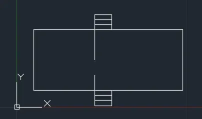
RESULT
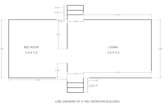
Figure C3 drawn using polyline tool, line tool, offset tool, dimension tool and using Relative rectangular coordinate system
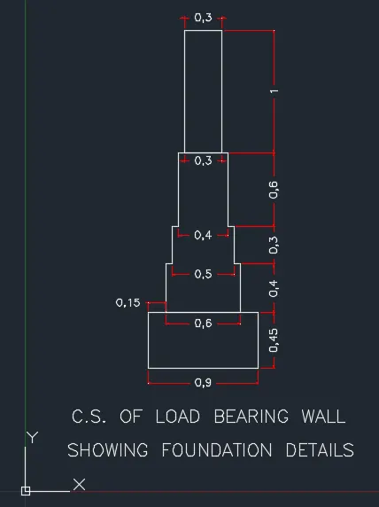
Q4. C4
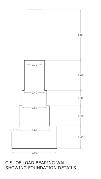
AIM : To draw the figure C4 in AutoCAD
PROCEDURE
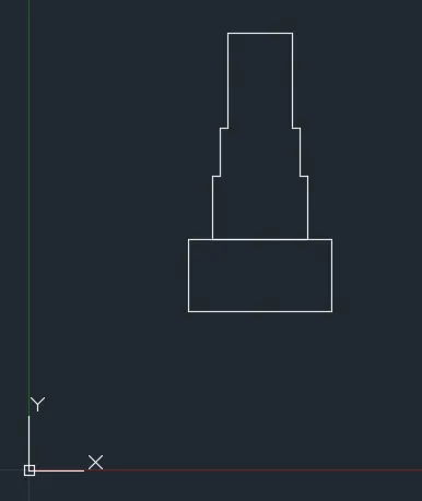
Type rectangle or rec in command box and press enter
Specify first corner point : 1,1 and press enter
Specify other corner point : @0.9,0.45 and press enter
Type polyline or pl in command box and press enter
Specify start point: 1.15,1.45 and press enter
Specify next point : @0,0.4 and press enter
Specify next point : @0.05,0 and press enter
Specify next point : @0,0.3 and press enter
Specify next point : @0.05,0 and press enter
Specify next point : @0,0.6 and press enter
Specify next point : @0.4,0 and press enter
Specify next point : @0,-0.6 and press enter
Specify next point : @0.05,0 and press enter
Specify next point : @0,-0.3 and press enter
Specify next point : @0.05,0 and press enter
Specify next point : @0,-0.4 and press enter
Specify next point : C (close the polyline)
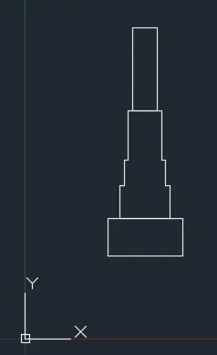
Type rectangle or rec in command box and press enter
Specify first corner point : 1.3,2.75 and press enter
Specify other corner point : @0.3,1 and press enter
RESULT
Figure C4 drawn using polyline tool, rectangle tool, dimension tool and using Relative rectangular coordinate system
Q5. C5
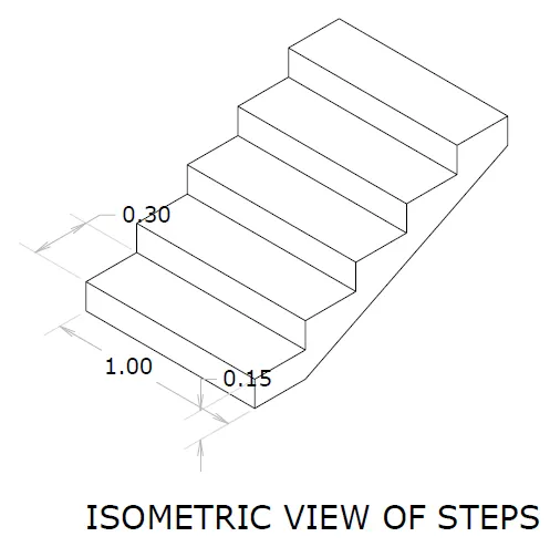
AIM : To draw the figure C5 in AutoCAD
PROCEDURE
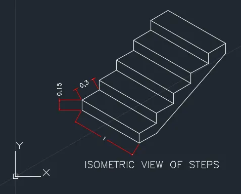
Go to grid and snap setting and turn on isometric view
Press F5 key to change the direction of the isometric view
Turn on ortho mode by pressing functional key F8
Type line or l in command box and press enter
Specify first point: 1,1
Specify next point : move the cursor to the right side of the point and type 1 as its distance and press enter
Specify next point : move the cursor to the top of the last point and type 0.15 as its distance and press enter
Specify next point : move the cursor to the left side of the last point and type 1 as its distance and press enter
Specify next point : c (close the line command)
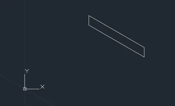
Press F5 key to change the direction of the isometric view to
Type line or l in command box and press enter
Specify first point : turn on the osnap F3 move the cursor to the top right corner of the riser drawn earlier and click on it
Specify next point : move the cursor to the right side of the point and type 0.3 as its distance and press enter
Specify next point : move the cursor to the top of the last point and type 0.15 as its distance and press enter
Specify next point : move the cursor to the right side of the last point and type 0.3 as its distance and press enter
Specify next point : move the cursor to the top of the last point and type 0.15 as its distance and press enter
Specify next point : move the cursor to the right side of the last point and type 0.3 as its distance and press enter
Specify next point: move the cursor to the top of the last point and type 0.15 as its distance and press enter
Specify next point : move the cursor to the right side of the last point and type 0.3 as its distance and press enter
Specify next point : move the cursor to the top of the last point and type 0.15 as its distance and press enter
Specify next point : move the cursor to the right side of the last point and type 0.3 as its distance and press enter
Specify next point : move the cursor to the down of the last point and type 0.15 as its distance and press enter
Press esc and close the line command
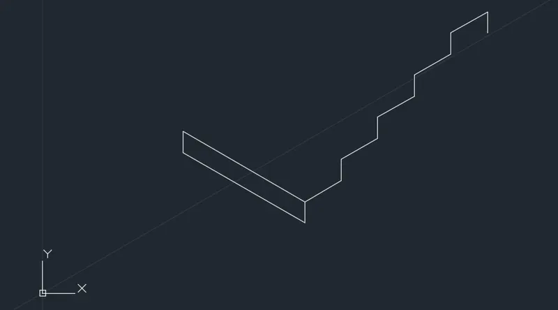
Type copy or co in command box and press enter
Select the tread and riser drawn in the previous step and press enter
Specify the base point : select the edge of the first riser
Specipy the second point : select the edge of the riser drawn before
Press esc to close the copy command
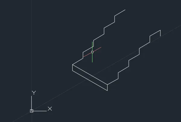
Type copy or co in command box and press enter
Select the riser drawn in step 1 and press enter
Specify the base point : select the edge of the first riser
Specipy the second point : select the edge of the next riser drawn
Specipy the second point : select the edge of the next riser drawn
Specipy the second point : select the edge of the next riser drawn
Specipy the second point : select the edge of the next riser drawn
Specipy the second point : select the edge of the next riser drawn
Press esc to close the copy command
Type line or l in command box and press enter
Specify first point : turn on the osnap F3 move the cursor to the top right corner of the riser drawn earlier and click on it
Specify next point : move the cursor to the right side of the point and type 0.3 as its distance and press enter
Specify next point : move the cursor to the top of the point and join the line.
Press esc to close the copy command
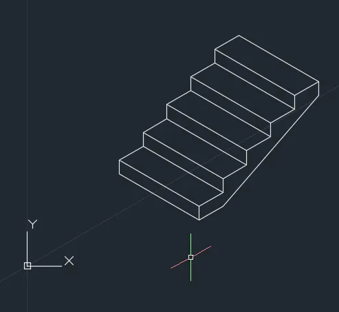
RESULT
Figure C5 drawn using line tool, copy tool and dimension tool
Q6. C6
AIM : To draw the figure C6 in AutoCAD
PROCEDURE
Go to grid and snap setting and turn on isometric view
Press F5 key to change the direction of the isometric view
Turn on ortho mode by pressing functional key F8
Type line or l in command box and press enter
Specify first point: 1,1
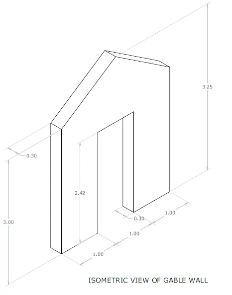
Specify next point : move the cursor to the right side of the point and type 1 as its distance and press enter
Specify next point : move the cursor to the top of the last point and type 2.42 as its distance and press enter
Specify next point : move the cursor to the left side of the last point and type 1 as its distance and press enter
Specify next point : move the cursor to the down of the last point and type 2.42 as its distance and press enter
Specify next point : move the cursor to the left side of the last point and type 1 as its distance and press enter
Specify next point : move the cursor to the top of the last point and type 3.25 as its distance and press enter
Specify next point : move the cursor to the left of the last point and type 3 as its distance and press enter
Specify next point : c (close the line command)
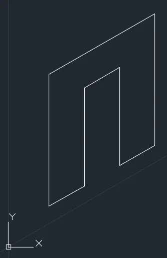
Type chamfer in command box and press enter
(TRIM mode) Current chamfer Dist1 = 0.0000, Dist2 = 0.0000
Select first line : D (distance)
Specify first chamfer distance : 1.5 and press enter
Specify second chamfer distance : 0.25 and press enter
Select first line : horizontal line at top side
Select second line : vertical line at side
Type chamfer in command box and press enter
(TRIM mode) Current chamfer Dist1 = 1.5000, Dist2 = 0.2500
Select first line : horizontal line at top side
Select second line : vertical line at side
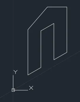
Type copy or co in command box and press enter
Select the all the lines drawn
Specify the base point : select the edge of the first line
Specipy the second point : give a distance of 0.3 and press enter
Press esc to close the copy command
Type erase or e in command box and press enter
Select object : which are intersecting each other and press enter
Press esc to close the erase command
Type line or l in command box and press enter
Specify first point: 1,1
Specify next point : move the cursor to the left of the point and type 0.3 as its distance and press enter
Press esc to close the line command
Join all the lines by repeating the line command
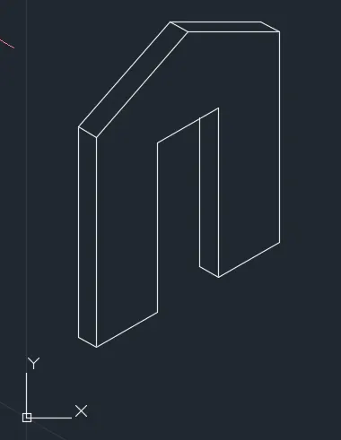
RESULT
Figure C6 drawn using line tool, copy tool and dimension tool